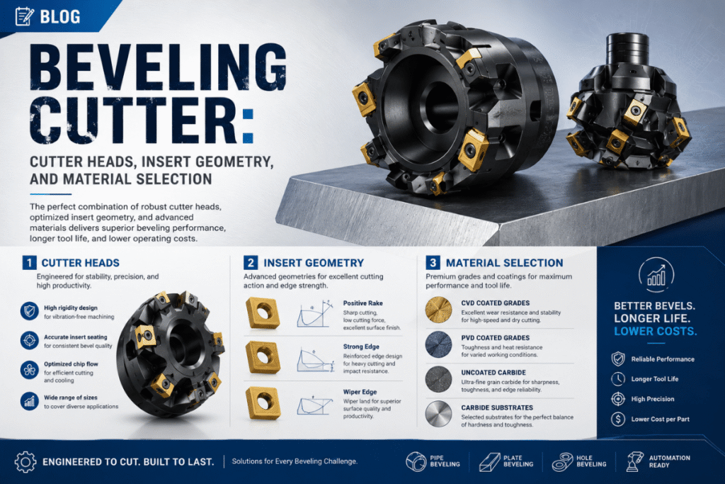
間違ったベベリングカッターインサートは、単なる交換用インサートよりもはるかに多くの費用がかかります ー 拒否されたベベル、検査の失敗、汚染された溶接ゾーンの費用がかかります 適切なベベリングカッターは、ワークピースの材料と体積に一致する適切なインサートグレード、形状、およびコーティングの選択に依存します このガイドe xxは、4 つの主要なカッタータイプ、材料/グレードの選択、コード要件に基づく30-45° の角度の選択、パイプとプレートの形状の違い、摩耗の認識方法、およびステンレス鋼と二重パイププログラムの2025-2026 インサート市場の読み方を説明します。.
クイックリファレンス: ベベリングカッターのスペック
| 一般的な斜角 | 30° (API 1104 メインライン) / 37.5° (ASME B31.3/B16.25) / 45° (AWS D1.1 CJP) |
| カッターの種類 | 刃先交換式超硬インサート ・ ろう付け超硬 ・ HSS ブレード ・ 面取りミル |
| 典型的な挿入ジオメトリ | 掻き角 0° ~15° ・ リリーフ角 5° ~12° |
| 材料の範囲 | 炭素鋼・ステンレス (304/316L) ・ アルミ ・ デュプレックス / インコネル |
| RESIZEマシンスペック | 切断深さ 0 ~ 25 mm ・ 角度 15° ~ 75° ・ 2.8 kW ・ 2,000 ~ 6,000 RPM |
| 交換信号 | カット中または目に見えるエッジチッピング中の振動の開始 |
ベベリングカッターとは何ですか? (そしてベベリングマシンとどのように異なるか)
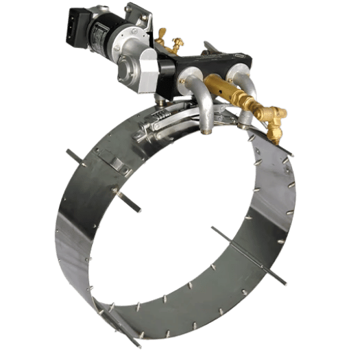
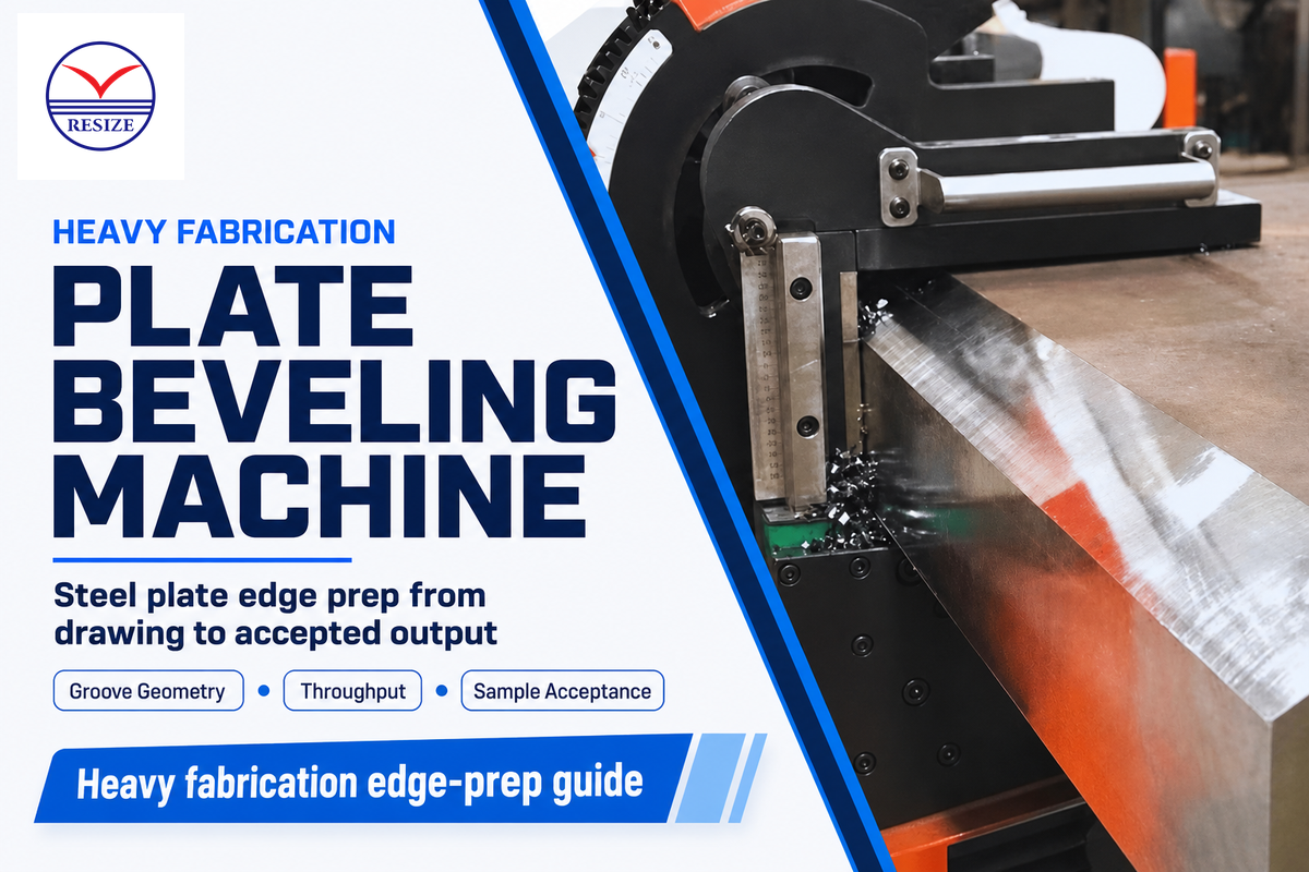
ベベリングカッターは、ツールヘッドの交換可能な切削インサートまたはブレードとして定義されます ベベリングマシン, 、斜角溶接接合部を作成するために材料の除去を担当 機械本体コンポーネント (モーター、クランプ、フィードコントロール) は再利用可能なインフラストラクチャー ⁄ 数千の切断に対応するために構築された資本資産。 、逆に、カッター自体は、最終的に交換を必要とする定義された耐用年数を持つ消耗品です。.
溶接準備アプリケーションをトラブルシューティングする場合、それらを区別することが非常に重要です。 aの場合 フライス盤と面取り機 それは間違った溶接準備構成を作り出します、失敗は挿入に起因する時間の99%です。 失敗モードを誤診すると、90秒で交換用カッターがあれば解決できたはずの技術者による不要な(そして高価な)機器の訪問につながります。.
キー ジオメトリ用語を挿入します
面取りインサートがどのように切断されるかを定義する3 つの幾何学的パラメーターは次のとおりです:
| パラメータ | 典型的な範囲 | 切断への影響 |
|---|---|---|
| レーキアングル | 0°–15° | より高いすくい=より鋭いせん断、より少ない切断力、硬い材料のより短い寿命 |
| リリーフ角度 | 5°–12° | 刃先の後ろのクリアランス ⁄ かかとがベベルフェイスに擦れるのを防ぎます |
| 鼻の半径 | アプリケーション固有 | 半径が大きくなると、表面仕上げとインサートの強度が向上します。半径が小さくなると、エッジのシャープさが向上します |
任意の面取り機の交換用インサート キットを注文する際には、形状 (正方形、三角形、円形)、グレード (C6、C8、サブミクロンカーバイド)、コーティング (コーティングされていない、TiAlN、PVD 多層)、およびノーズ半径の 4 つの情報を含める必要があります。面取り機のモデルとその工具の取り付け方法によって互換性が決まりますが、これらは、注文のために特定の機械プラットフォームが特定された場合の標準仕様ポイントです。.
RESIZE フライス盤およびベベル盤はすべて、切断深さ 0 ~ 0.98 インチ (0 ~ 25 mm)、角度 15° ~ 75° をカバーし、2,000 で回転する 3.7 馬力 (2.8 kw) モーターによって駆動される、容易に入手可能な割り出し可能なインサート カッターを使用しています。 ~6,000 rpm ――ライトゲージチューブから重壁プレート、大口径パイプまで、あらゆるものを扱うのに十分です。.
工作機械カートで処理される材料タイプごとに交換用インサートを 1 セット保管してください。店舗エリアではありません。オペレーターは、エッジの摩耗による振動の最初の兆候を聞いたら、90 秒以内にインサートを新しい刃先に変更できます。倉庫まで歩くと、完全な溶接継手を始める前に、仕様上のパイプを 1 本追加する機会を逃す可能性があります。.
ベベリングカッターの種類: インデックス可能なインサート、HSS ブレード、面取りミル
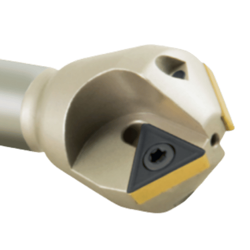
さまざまな作業量に適したベベリングカッターには主に 4 つのタイプがあります。これらをどのように適用するかは生産速度と材料に依存するため、ベベルあたりの速度、寿命、コストが決まります。したがって、このタイプはあらゆる溶接準備プロセスに対する基本的な選択となります。.
4つのカッタータイプ
1. インデックス可能なインサートは、数個から 8 個の刃先を備えたインデックス可能な材料であるインデックス可能な炭化物で作られています。これにより、インサートを回転させ、金属の個々のビットを再研磨するのではなく、複数の刃先を使用することができます。インデックス可能な炭化物インサートは、炭化物サプライヤーに応じて、HSS インサートで可能な約 4 倍の速度で加工できます。インデックス可能なインサートは、サイクルタイムが懸念される中~大量の生産量に使用されます。.
2. ろう付け超硬工具は、超硬チップをスチールシャンクに溶接し、必要な輪郭に部品全体を成形することによって設計されています。これらは、標準的な刃先交換式インサートでは利用できないカスタマイズされた構成を持つことができ、個々の工具価格は低くなります。ただし、欠点は、エッジが鈍くなったときに再研磨のために工具全体を生産から外す必要があるため、機械のダウンタイムが増加することです。特殊な構成や、経験豊富な工具研削盤を備えた低生産の製造環境に適しています。.
3.HSS (高速度鋼) ブレードの初期価格は最も低い 通常、業界データによると、HSS の切断速度は、同一の用途では炭化タングステンの約 4 分の 1 です。これは、スループットを最大化することが目的ではない現場での修理、独自の切断、またはライトゲージ材料に適しています。ステンレス鋼の生産ラインで HSS を利用すると、サイクル時間が大幅に長くなるため、インサートのコスト上の利点が打ち消される可能性があります。.
4.面取りミルは、エッジ面取りを作成するためにCNCマシニングセンタで使用される特別なツールであり、面取りパイプまたはプレート用のインサートと混同しないでください。面取りミルの設計(クランプ方法、形状、振れ公差)は、ポータブルまたは固定面取り機械で使用されるものとは異なります。したがって、それらは交換可能ではありません。パイプ上の溶接準備用の面取りインサートの代わりに面取りミルを選択しないでください。.
| タイプ | 最高の適用 | 切断速度 | インサート Life | 相対コスト |
|---|---|---|---|---|
| 索引付け可能な炭化物 | 中高生産;すべての材料 | 高い (~4 × HSS) | ロング (マルチエッジ) | 中~高(挿入ごと) |
| ろう付けされた炭化物 | 専門的な形状;少量 | 高い | ミディアム(再研磨が必要) | 低~中 (ツールごと) |
| HSS ブレード | フィールド修理; ワンオフカット; ライトゲージ | 低 (~1⁄4 炭化物) | 短い | 最低(ブレードごと) |
| 面取りミル | CNCマシニングセンタのみ | ハイ (CNC) | 長 (CNC 条件) | 高い |
3 要素ベベリングカッター選択マトリックス
カッターの種類とグレードの選択は、ワークピースの材料と生産量によって異なります:
| ワーク材質 | フィールド/修理 (1 ~ 50 カット/月) | 巻半ば (50 ~ 500 カット/月) | 生産(500+カット/月) |
|---|---|---|---|
| 炭素鋼 | HSS ブレード | 索引付け可能な炭化物、C6 の等級 | 索引付け可能な炭化物、C8 またはコーティング |
| ステンレス304/316l | 刃先交換可能な超硬、pvd-tialn | 刃先交換可能な超硬、pvd-tialn | 刃先交換可能な超硬、サブミクロン PVD |
| アルミニウム | インデックス可能な炭化物、コーティングされていません | 刃先交換可能な炭化物、研磨済み、コーティングされていません | 刃先交換可能な炭化物、研磨済み、コーティングされていません |
| デュプレックス/インコネル | 刃先交換可能な超硬、サブミクロン PVD | 刃先交換可能な超硬、サブミクロン PVD | 刃先交換可能な炭化物、CBN またはサブミクロン PVD |
指数関数的炭化物: 利点
- 4 HSS の切断速度 * シフトあたりのスループットの向上
- あらゆる新鮮なエッジで一貫したジオメトリ
- 広い等級およびコーティングの利用できる(C6/C8/サブミクロン/PVD)
- 再研磨する必要はありません - フリップすると 2 分以内に戻ります!
- 予測可能な工具寿命により、インサートの消費計画が可能になります
HSS ブレード: 制限事項
- 切断速度が低下 ⁄ ベベルあたりのサイクル時間が長くなります
- エッジ寿命が短くなる ――ブレードの交換頻度が高まる
- 熱がすぐに蓄積するため、ステンレス鋼では乾燥できません。.
- 二重、超二重、またはニッケル合金には適していません
- 炭素鋼ではコスト削減が >50 カット/月で蒸発します
カッター角度と溶接コードの一致: 30° 、37.5° 、45° の選択ルール
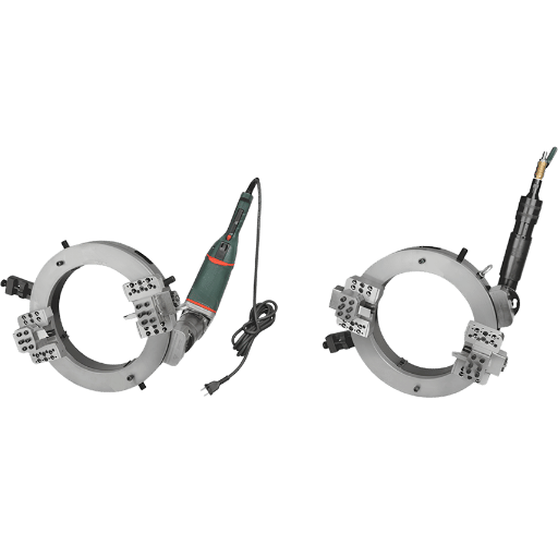
ベベル角度は、現場で行う選択ではありません; 溶接手順仕様 (WPS) で指定されたコードの要件です ほとんどの構造およびプロセス配管プロジェクトで使用される3 つの典型的なベベル角度は、30° 、37.5° 、および45° で、それぞれが特定のコードアプリケーションに関連付けられています 機械が間違った角度に設定されている場合、ベベルエッジの結果の溝の形状はWPSのそれと一致せず、溶接ベベルは検査に合格しません。.
| コード | ベベルアングル | 寛容 | 代表的なアプリケーション |
|---|---|---|---|
| AWS D1.1:2025 (CJP) | 45° | ±5° の | Structural steel, CJP groove welds |
| AWS D1.1 (PJP) | 30° min | ±5° の | Partial penetration structural welds |
| API 1104 (mainline) | 30° | ±5° の | Cross-country pipeline girth welds |
| API 1104 (facility piping) | 37.5° | ±2.5° | Plant and facility piping tie-ins |
| ASME B31.3 / B16.25 | 37.5° | ±2.5° | Process piping, standard wall ≤22 mm |
When two beveled edges of pipe are brought together, the overall groove angle is twice the bevel angle. For example, if a drawing specifies “75 groove,” each of the beveled ends of the pipes needs to have a 37.5° bevel- not 75°. mistaking the groove angle requirement for a bevel angle setting has been identified as a cause of costly project rework. Always confirm whether a dimension on a drawing refers to a single-sided bevel or a full-pipe groove angle before adjusting the machine setting.
AWS D1.1:2025 (the 25th edition) requires 45° for prequalified Complete Joint Penetration (CJP) groove welds on structural steel. This translates to an included groove angle of 60°. A machine angle setting should be adjusted to the bevel angle, and not the groove angle, if you are completing an AWS D1.1 CJP weld prep-set the machine to 45°, not 60°. Setting to the included angle will produce a bevel that is excessively steep, wastes materials and the resulting groove profile will not match the prequalified geometry.
For a full breakdown of bevel standards across codes, see RESIZE’s full bevel angle and chamfering standards guide and the bevelling standards reference.
⚙ Engineering Note
Under normal operating conditions, the machine setup of a well-maintained pipe beveler should produce a cut capable of 1 better – well within 2.5-5 tolerance code limits. Check with a bevel gauge at 12, 3, 6 and 9:00 positions around the circumference of the pipe on the first finished product. On circumferential welds on large diameter pipe, it does not take a lot to throw the machine setting out.
Cutter Material & Grade Selection: Carbide, HSS & Coatings by Workpiece
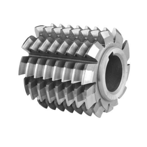
You need a machining strategy for your workpiece. Selection of insert grade and coating must be based upon the workpiece material, not on whatever inserts may be in the holder already.
Machining stainless or aluminum using the wrong coating not only reduces insert life – it leaves surface contamination that will adversely impact the weld zone or result in an a hygiene non-conformance.
| Workpiece | Recommended Grade | Coating | Key Reason |
|---|---|---|---|
| Carbon steel (low/medium) | C6 or C8 tungsten carbide | Uncoated or TiN | Cost-effective; TiN adds wear resistance at moderate temperatures |
| ステンレス304/316l | Sub-micron fine-grain carbide | PVD-TiAlN | Low thermal conductivity of SS; TiAlN resists heat buildup at the cutting edge |
| Stainless (sanitary/3-A) | Dedicated stainless insert | PVD-TiAlN | MUST be separate from carbon-steel tooling — iron contamination risk |
| Aluminum 6061/5052 | Fine-grain carbide | Uncoated, polished flutes | TiAlN causes aluminum chip welding on insert — see warning below |
| Duplex / Super-duplex | Sub-micron PVD carbide | AlTiN or multi-layer PVD | High work-hardening rate requires sharp, coated inserts at controlled speeds |
| Inconel / Nickel alloys | Sub-micron carbide or CBN | Multi-layer PVD | Extreme heat generation; reduce cutting speed 30–40% versus carbon steel parameters |
Field machinists unanimously complain that TiAlN-coated inserts machined on aluminum produce weld on: cutting edge on cutting insert within the first few parts.
Use only uncoated, polished carbide tooling for aluminum beveling. This not just a small difference in tool life, it is difference between using the tool and destroying it in one pass.
During machining, iron particles carried in cut, are carried with pipe material out of cutting zone on to finished stainless surface. When it rains, the deposited iron corrodes creating rust staining on the surface of the stainless and can compromise corrosion resistance of finished stainless pipe in the weld area, as discussed on various forums of American Welding Society. For food, drug, and other hygiene oriented piping, 3-A sanitary standard has clear language stating that only stainless steels are suitable for food-contact surfaces and tooling.
Therefore, only dedicated stainless tools should be employed for stainless welding pipe beveling jobs -never use the same inserts in a carbon steel program and a stainless program.
Although carbide is capable of machining both materials, there are risks in running carbon steel cutting tool for stainless steel – which involves iron particles depositing onto the stainless surface, causing rust staining.
For hygienic applications like food/drug-related pipe, a hygiene non-conformance arises if such contamination occurs. Stainless pipe work requires the maintenance and segregation of cutting tools specific to material-type, to prevent cross-contamination; a must if quality or hygienic standards are to be met, including documented process control of tooling segregation.
Use appropriate insert speed. For duplex and super duplex materials that have a high degree of work hardening, it is especially important that cutting speed be mode rated, when using carbide tools, to avoid over-hardening the cutting face of the pipe. This extra hardened area at weld joint requires special penetration effort by the welder.
Use a slightly slower speed and check for wear on the insert regularly.
Pipe Cutting and Beveling Cutters vs. Plate Beveling Cutters: Key Differences
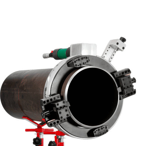
Differences between plate and pipe and therefore tool geometry, machining center, etc., must be clearly understood.
Forcing an angle on the workpiece out of profile of a plate bevel on circumferential of pipe, will lead to incorrect angle.
Pipe beveling: The cutting insert rotates 360 degrees around the end of the pipe. On an OD-mount machine, the insert follows the full circular circumference of the pipe and any such variation of angle must be avoided throughout that 360 degree orbit. Drift in angle, whether by the worn insert, the shifting machine clamp or variations in the feedrate will produce a bevel that is outside of tolerances at some portion around the pipe periphery.
Plate beveling: A linear path that follows the shape of the cut in a straight line across a plate. Simpler geometry with no rotational component, therefore no angular requirements to worry about for the entire circumference and nothing to monitor for angular drift over time.
| パラメータ | Pipe Beveling Cutter | Plate Beveling Cutter |
|---|---|---|
| Cut path | Circumferential (360°) | Linear |
| Mandrel required | Yes (ID-mount) or OD clamp | No |
| Angle drift risk | High (manual pipe rotation) | ロウ |
| Common defect | “Fish-mouth” (angle wanders around circumference) | Inconsistent depth along plate length |
| Cutter geometry | Designed for orbital engagement | Designed for continuous linear feed |
| Typical insert shape | Square or triangular | Rectangular or special profile |
OD-mounted (external clamp) pipe beveling machines achieve a ‘fish-mouth free’ bevel by keeping the cutting tool bit at a fixed angle while a drive ring rotates around the circumference of the pipe. For pipe that is already installed in a system, split frame portable bevelers swing around the pipe to clamp the ends without the need to remove the pipe or spool from the system. Medical, food and pharmaceutical (MFP) piping systems use the OD type of internal piping bevel machines, or external clamp machines for high-end applications because of their ability to avoid damaging the pipe interior surface and thus avoids the creation of ‘jaw marks’ that bacteria could potentially adhere to within the tube for sanitary applications.
After each bevel, test at the 12, 3, 6, and 9 o’clock position using a qualified bevel measurement gage. Manually rotating the pipe-instead of mechanically rotating the machine orbit around the pipe-is the primary reason forbevel-angle variations on circumferential welds and piping systems. The only way to eliminate thisvariable is with a mechanically driven OD-clamping machine that orbits around the pipe.
See also our pipe beveling machine selection guide, the overview of pipe beveler types and working principles, and the full フライス盤と面取り機 product range.
Portable vs. Machine-Mounted Beveling Cutters: Field vs. Production Selection
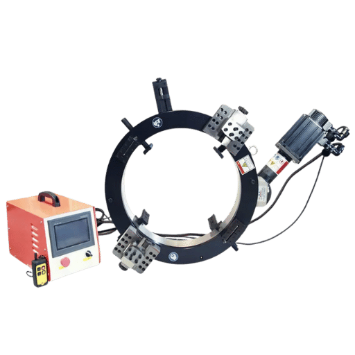
You may also use the same insert grade for a portable handheld beveler or a static CNC beveling machine; however, they provide different levels of achievable angle precision, which may determine your equipment choice based on code specifications.
| Equipment Type | Angle Accuracy | 最高の適用 |
|---|---|---|
| CNC / stationary | ±0.5° | High-volume production; tight-tolerance programs (nuclear, aerospace, offshore) |
| Portable electric | ±1° の | Field work; shop flexibility; most standard code work |
| Pneumatic portable | ±1~2° | Hazardous and explosive zone (spark-free) field work |
| Manual / hand-held | ±2–3° | Touch-ups; site repairs; non-code bevel work |
Drive Type Selection
Drive Type: “Drive type” refers to how the beveler gets power-it is less about output power itself, and more about environmental concerns and how efficiently power is applied:
Pneumatic (Pneumatic: Air-Powered) – Ideal for ATEX/Zone 1 hazardous areas like oil & gas facilities and refineries because it eliminates the possibility of creating sparks, ensuring the cold-cut mechanical beveling process is a safe alternative to torch cutting or open-flame grinding. However, this drive type requires an adequate supply of compressed air at the job site.
Electric (Electrical: Wire-Powered) – Easiest to set up and use, requiring only a power source. Suitable for most fabrication environments and on-site applications where sparks are not a hazard. A standard 1 “precision grade” portable electric pipe mill beveled will satisfy all commonly used code standards (which commonly specify 2.5-5° angular tolerances).
Hydraulic (Hydraulic: Fluid-Powered) – Offers high torque consistently across the entire speed range of the machine. This is ideal for thick wall applications (wall thickness >25 mm / 1”) and for high-production rates when aggressive feed rates and depths are applied to shorten cycle times. Higher infrastructure requirements but the application of constant, uniform torque to heavy wall cuts is measured as improved surface finish compared to other power sources.
Compared with プラズマ切断機, cold mechanical beveling produces no heat-affected zone and no oxidation on the bevel face — critical for stainless steel and alloy programs where HAZ must be minimized. See RESIZE’s full CNC milling and beveling machine range for stationary options.
For your Pharma or Food Grade Stainless Steel Programs : Make sure you have your Electric Drive + External Clamping + dedicated PVD Coated inserts – and list all three in your WPS supporting record documents; Auditors are looking at this evidence in Piping fabrication for food/pharma.
Beveling Cutter Wear Signs, Replacement Criteria & Maintenance Checklist
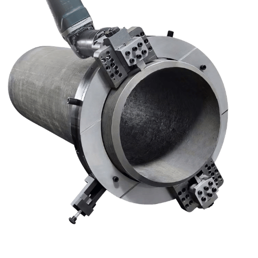
Most people run their inserts until the edges start to show clear chipping – THIS IS THE WRONG SIGNAL. Visible chipping of insert edges means that several pieces have already been run after your bevel quality has degraded & there is increased inspection risk.
”A clear sign of wear is increased vibration during cutting — indicative of loss of edge and a consequent reduction in precision.”
| Wear Sign | What It Means | Action |
|---|---|---|
| Vibration or chatter onset | Edge dulling — loss of cutting sharpness | Replace or rotate insert immediately |
| Surface finish deterioration | Insert geometry worn past optimal | Rotate to fresh edge |
| Dimensional drift (bevel angle shifting) | Insert wear changing effective geometry | Replace insert; re-verify angle on test cut |
| Built-up edge (BUE) on stainless | Wrong chip load or missing cutting fluid | Reduce feed rate; check coolant supply; replace insert |
| Visible edge chipping | Late-stage wear — bevel quality already compromised | Replace immediately; review recent bevels |
Vibration onset during the cut is the first telltale wear sign.
Replace or rotate inserts at first vibration- BEFORE edge wears significantly and well BEFORE bevel geometry drifts out of tolerance.
Use cutting fluids to reduce friction & temperature- this drastically improves tool life.Stainless steel or duplex alloys: Always use a cutting fluid. Without a fluid, your insert will experience Built Up Edge (BUE), your workpiece will harden, and you risk insert fracturing and poor surface finish.Aluminum or Titanium:Use uncoated, polished inserts without a cutting fluid or with a light mist. While titanium offers the same type of work-hardening effect on an insert from excessive load or from lack of coolant/lubrication, and an insert with TiAlN (or any) coating risks aluminum chip-welding directly onto the insert itself even with sufficient coolant/lubrication, either is very detrimental.
メンテナンスチェックリスト
- Six mistakes lead to the overwhelming majority of beveling failures & insert failures: 1.Material Selection-Using uncoated standard-grade carbide on stainless, duplex, etc. The work-hardens so rapidly that it destroys the tool’s edge very quickly. 2. Contamination-Running stainless steel with carbon-steel cutting tools; this deposits iron on the bevel face and rust stamps your piece.3.Dry Cutting.-Running austenitic stainless without a cutting fluid is the fastest way to create heavy Built Up Edge (BUE) on the tip & progressively harder surface work on the workpiece near the edge.
4. Bad Replacement-Waiting until the insert edge is chipped to replace; by then it has already degenerated through multiple parts.
5. Chip Load-Either too heavy, to build heat and accelerate wear, or too light, causing “rubbing” of the edge and thus increased wear.
6.
Incorrect Angle Setting-Setting the machine to the included groove angle instead of a Single-side bevel angle, this results in twice the expected bevel.
- Insert edge check- before start-up; Inspect cutting edge visually for any chips or BUE from previous production run.
- Test cut- Check bevel angle on one test piece-verify on all sides of the pipe.
- Monitor for vibration; during first production piece, monitor the cutting tool-replace or rotate if any vibration.Zegbrk_0010Cutting fluid selection; apply correct type and amount per material.
- Wash out machine and clamping surfaces free of chips and debris after each use (use carbon steel material with close tolerance of stainless insert for best result of minimizing chip contaminating).
- Separate of all tool sets by materials (e.g. steel & stainless inserts) in their labeled storage bins — never mix among different material programs.
2025–2026 Outlook: Precision Inserts, PVD Coatings & CNC Integration
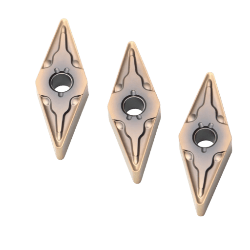
Three key market trends in 2026 for the selection of beveling cutters for fabrication programs. These can help guide tooling investment decisions and WPS update ahead of necessity.
Key Market Statistics: Beveling Cutter Inserts 2024–2033
| Cutting tool inserts market (2026→2033) | ~$6.5 billion → ~$8.7 billion (projected) |
| PVD-coated insert market (2024→2033) | $2.4 billion → $4.1 billion (+71% expansion in PVD adoption) |
| “Beveling tools” search trend (May→Oct 2025) | +30% volume increase (RESIZE DataForSEO market monitoring) |
Trend 1: PVD Coating Migration to Mid-Market
Multi-layer nano coatings (AlTiN, multi-layer PVD, etc), once exclusive to aerospace machining (CNC programming), are now part of mid-price level bevel insert geometric and grades. Stainless, duplex, and any non-ferrous fabrication that has used TiN coated inserts may step into significant new levels of performance without changing their machine platforms; as the gap between standard inserts and micron-level (e.g., sub-micron) PVD insert costs have contracted sufficiently that a greater tool life likely overcomes cost of insert over time.
Trend 2: CNC Precision Tolerance Pressure
Increased bevel tolerances within some (e.g. offshore, nuclear, and aero) fabricated product specifications, even when codes (e.g., AWS D1.1, ASME B31.3) remain broader (e.g., 2.5 deg). Specification engineers are now authoring supporting documents (to the weld procedure specification or WPS) that call for 1-deg bevel instead of the code’s allowances of 2.5-5.
If your work is for such tight tolerance welding, CNC equipment (vs. portable bevel machines), at 0.5 deg accuracy, becomes indispensable. Fabricators still employing only portable bevel solutions for high-specification welding should plan equipment change-out to machine integrated type.
Trend 3: AWS D1.1:2025 (25th Edition)
Changes in code-specified bevel angle tolerances for full penetration welds in the 2025 Edition of the Structural Welding Code. Fabricators operating to the AWS D1.1 standard should plan review of WPS specifications against the 2025 Code and its prequalified weld details. As written in the 2020 edition, a 2020- qualified weld procedure may require update (and machine settings retooling) to align with the new AWS D1.1 Code Pre-Qualified Joint Details.
2026 Tooling Investment Decision Framework
When purchasing newbevel machine tooling for 2026, rank your purchases by order of importance:
- New sub-micron PVD-coated carbide inserts for stainless and duplex jobs – the advantage is visible over time (insert life and consistency) in both the speed and quality of finish, as well as accuracy at full speed.
- Separate sets of inserts (tooling, machine) per material. Dedicated cutting tools are necessary for stainless and other exotic metals to avoid any risk of contamination.Label the inserts.
- Check your AWS D1.1:2025.Code compliant bevel angle should be established in WPS.
- Re-evaluate of your current bevelling equipment if you’re dealing with (or anticipate future demand) of work specifying bevel angle tighter than 2 degrees (i.e., within 1).CNC beveling machines holding 0.5 (vs portable that would be at least 1-1.5) are becoming a more viable option to keep the fabrication meeting a given standard.
Explore RESIZE’s CNC milling and beveling machine range for equipment designed to hold ±0.5° across the full 15°–75° angle range on carbon steel, stainless, and specialty alloys.
よくある質問frequently Asked Questions
Q: What is a beveling tool used for?
回答を見る
ベベリング カッターは、パイプ端またはプレート端に角度付き面 (通常 30° 、37.5° 、または 45° ) を加工し、完全貫通溶接に必要な溝の形状を作成します。超硬または HSS インサートを使用した冷間機械切断では、熱影響ゾーンが残らないため、溶接端の HAZ が耐食性と接合強度を損なうステンレス鋼、二相、および高合金材料の要件となります。.
Q: What are the most common mistakes when beveling?
回答を見る
Seven common beveling errors: (1) Using the incorrect insert grade for the work material — for example, using uncoated or TiN-coated carbide instead of TiAlN-based PVD coating for stainless. (2) Contaminating carbide tools with carbon steel, depositing iron traces that cause rust spots on the bevel. (3) Not using cutting fluid on stainless or duplex steel, which builds up edge material and progressively workhardens the bevel surface. (4) Not rotating or replacing inserts at the first signs of chipping — by that point, the last 50 bevels are likely out of spec. (5) Machining to the included groove angle instead of the single-side bevel angle, producing a bevel that is twice the target. (6) Skipping the initial test cut on scrap material — every production run should start with one calibration cut and a measurement. (7) Confirming the angle but not checking land width and root-face dimension after cutting — both affect weld fit-up and penetration depth; a calibrated bevel protractor takes under a minute per joint and catches dimensional drift before it compounds across a spool run.
Q: What is bevel cutting?
回答を見る
A bevel cut is the process of cutting a portion of material at a predetermined angle away from the end of a pipe or from the side of a plate edge, preparing the joint. The angle – typically 30 to 45-matches the “groove geometry” specified by a given weld procedure. Cold bevel cutting with HSS or carbide inserts leaves an HAZ-free bevel on either a pipe or plate edge, preserving the base-metal’s mechanical properties and corrosion resistance at the weld joint, unlike thermal cutting (e.g., plasma, oxy-fuel) which requires pre-weld grinding to remove the HAZ before welding sensitive materials like stainless.
Q: What does a beveling cutter cost — and when should I consider a full machine?
回答を見る
一般的なシングルインデックス可能な超硬インサートは、1 個あたり$5 から$25 (材料、形状、コーティングによって異なります) のコストです HSSカッターのセットは、$15 から$60 のコストです 容量と駆動方法によって異なりますが、一般的な直径に対して約$800 から$5,000 のパイプハンドリングパイプベベル盤を得ることができます 生産のために月に50 本以上のパイプをベベルで製造する予定がある場合、機械ベベル加工によって実現される時間の節約 (ベベルを手動で研削する、サーマルカットに加えて研削後処理を行う、またはサードパーティショップに送ると比較して) は、ほぼ確実に機械とインサートのコストをカバーし、6 から12 か月以内に工作機械による検査の成功率が手動で研削または熱切断された溶接の検査成功率を大幅に上回る可能性が高いため、このコストメリットはさらに増幅されます。.
Q: Do I need cutting fluids when beveling pipe?
回答を見る
it varies with material. Carbon steel is often bevelled dry in many shop environments but a little cutting oil will extend insert life dramatically. Stainless steel, duplex and nickel alloys always need to be beveled with the proper cutting fluid – cutting them dry builds up edge, workpieces begin to progressively workharden, and the inserts are used up much quicker. Aluminum is usually bevelled dry with plain, polished inserts; the only thing to be aware of on aluminum ischip welding from coated inserts – the machine is cool but the cutting edge is hot. In any pneumatic tool for use in spark-restricted environments like refinery settings and off-shore platforms always use nonflammable cutting fluid or confirm with your tool manufacturer that you can operate the tool within its rated capacity dry on that application.
Q: Can one beveling cutter handle multiple bevel angles?
回答を見る
In most shop-mounted beveling systems the setting for the cut angle will automatically adjust from perhaps 15 degrees to 75 degrees on a full range machine. An insert for such a machine covers a range of angles, not a single fixed angle; however, to obtain optimum machining efficiency and surface finish quality, select an insert geometry and grade that are suitable for both the desired angle and the workpiece material. For precision code work on any angle, test cut and measure your angle with a calibrated bevel gauge to confirm it matches your angle setting – no other indicator will work and setting errors occur with all mechanical angle-adjustments!
Ready to Upgrade Your Weld Prep Program?
Whether you’re ordering replacement carbide inserts for an existing milling/beveling machine or choosing a whole new machine system for your production line, cutting edge is the key. RESIZE milling/beveling machines are designed for accurate angles across the full 15°–75° range and accept standard indexable carbide inserts commonly available in standard and high-performance grades for both carbon steels and stainless/specialty alloys.
Explore RESIZE Milling & Beveling Machines
What is your pipe OD? Material? Contact our engineering team for insert and machine recommendations for your specific application.
This article was compiled and written by RESIZE’s technical content group with sources referencing AWS D1.1:2025, ASME B31.3, API 1104 and cutting insert technology from major carbide manufacturers. RESIZE provides a full line of milling and beveling machines and Our insert recommendations are based on well-established industry standards and machining practices and should always be checked against the parameters contained in your Welding Procedure Specification (WPS).
参考文献と情報源
- AWS D1.1/D1.1M:2025 — Structural Welding Code, Steel (pubs.aws.org)
- ANSI Blog — “AWS D1.1:2025 Structural Welding Code, Steel” (blog.ansi.org)
- 3-A Sanitary Standards — “Hygienic Materials of Construction and Surface Treatments” (3-a.org)
- American Welding Society Forum — “Cross contamination?” (carbon/stainless tooling) (app.aws.org)
- GBC Industrial Tools — “Pipe Cutting and Beveling Machines: Complete Guide” (gbcspa.com)
- Kedes Machine / bevelingtech.com — “Pipe Bevel Angles by Code: ASME, AWS & API” (bevelingtech.com)
関連記事
- What Is a Beveling Machine — resizeweld.com
- Beveling and Chamfering: Edge Prep Standards Guide — resizeweld.com
- Pipe Beveler: Types and Selection — resizeweld.com
- Milling and Beveling Machine (Product Range) — resizeweld.com