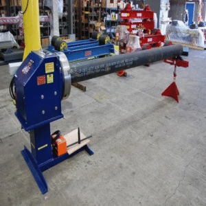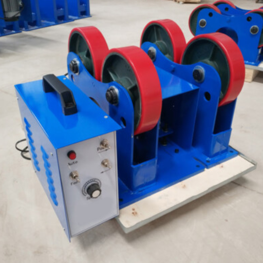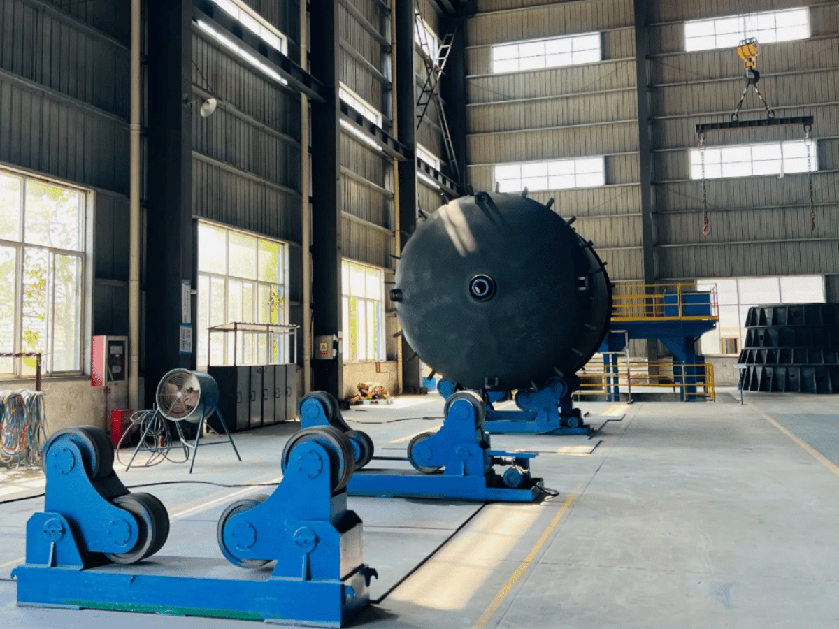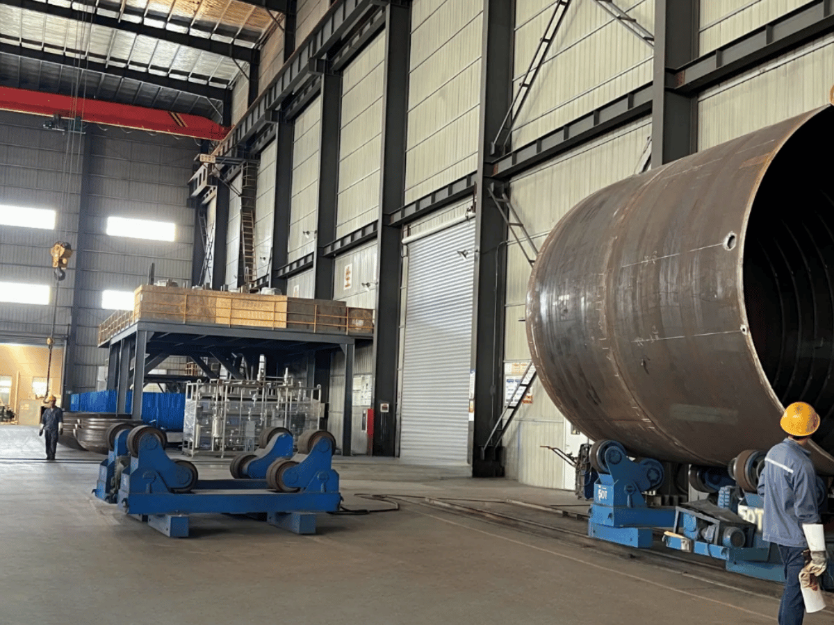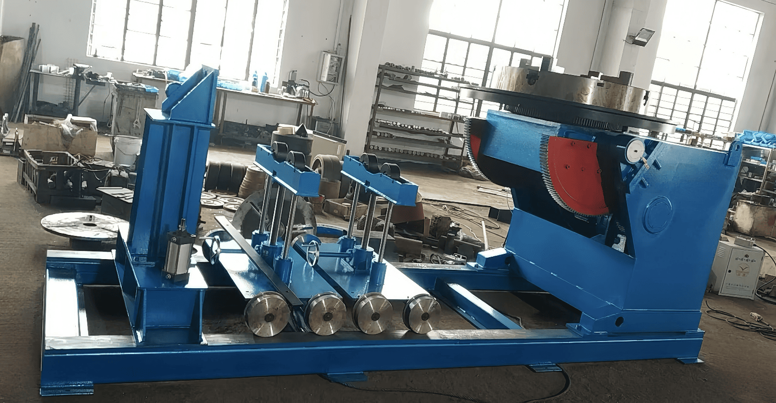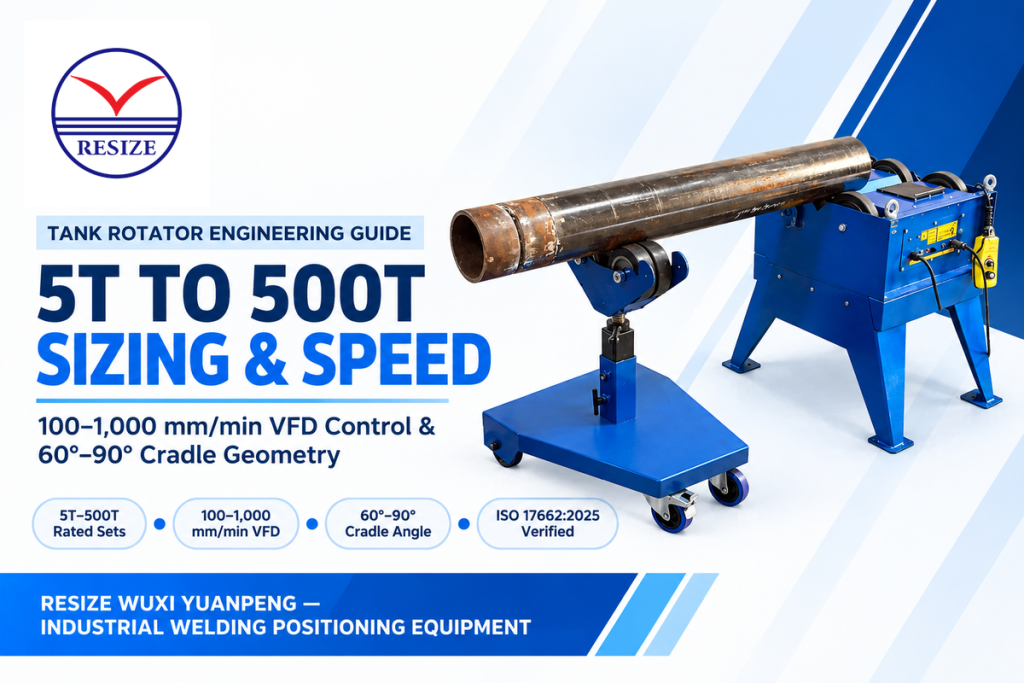
A tank rotator (also called industrial tank turning rolls or a powered welding roller bed) is a friction-drive positioning machine that rotates cylindrical workpieces at 100 to 1,000 mm/min (6 to 60 m/h) so girth welds stay in the flat 1G position. Standard RESIZE catalog sets span 5T to 500T, while broader industry lines cover 1T to 1,000T+. Standard industrial welding rotator systems pair one powered drive bed with one idler bed under stepless AC variable-frequency control. Engineering sizing rules in this guide multiply total vessel weight by a 1.3 to 1.5 traction safety factor and a 1.25 to 1.40 eccentricity factor. A roller cradle angle of 60° to 90° is a common starting range for sizing. Final cradle geometry is constrained by lateral stability, roller reactions, and the bed’s rated diameter range.
| Engineering Parameter | Standard Industrial Specification | Critical Design / Code Boundary | Verification Source |
|---|---|---|---|
| Rated Loading Capacity | 5T to 500T standard RESIZE catalog sets (Aubrik ZT/AD 1T–1,000T; custom fit-up to 2,000T) | Rated per 1 Drive + 1 Idler set; verify single-bed axle limit | RESIZE HGZ/HGK Catalog & Aubrik Design Data |
| Circumferential Speed Band | 100–1,000 mm/min (6–60 m/h) via stepless AC VFD | Surface speed verified per ISO 17662:2025 equipment calibration rules | RESIZE Product Specifications |
| Included Roller Cradle Angle | 60° to 90° optimum zone (within 45° to 110° operating window) | Below 45° risks lateral tipping; at 120° normal wheel load rises 73.2% | 60-Degree Cradle-Angle Sizing Benchmark |
| Roller Wheel Material | Shore 90A–95A polyurethane or induction-hardened forged steel | Polyurethane track contact capped at 80 °C to 90 °C (176 °F to 194 °F) | Elastomer Thermal & Hardness Limits |
| Anti-Drift Axial Creep Control | ±1.0 mm drift control with ~1° idler axle offset in US8342493B2 | Patent US8342493B2 specifies vessel roundness within 1 mm/m of diameter and recommends ~60% idler / 40% drive weight distribution | US Patent US8342493B2 |
| Safety & Calibration Standards | OSHA 29 CFR 1910.212(a), 1910.254, 1910.147; ISO 17662:2025 | Dedicated welding return connection and separate protective grounding; servicing lockout-tagout covers applicable electrical, mechanical, and hydraulic energy | OSHA General Industry & ISO 17662:2025 |
Tank Rotator Operating Mechanics: How Drive and Idler Rollers Control Surface Speed
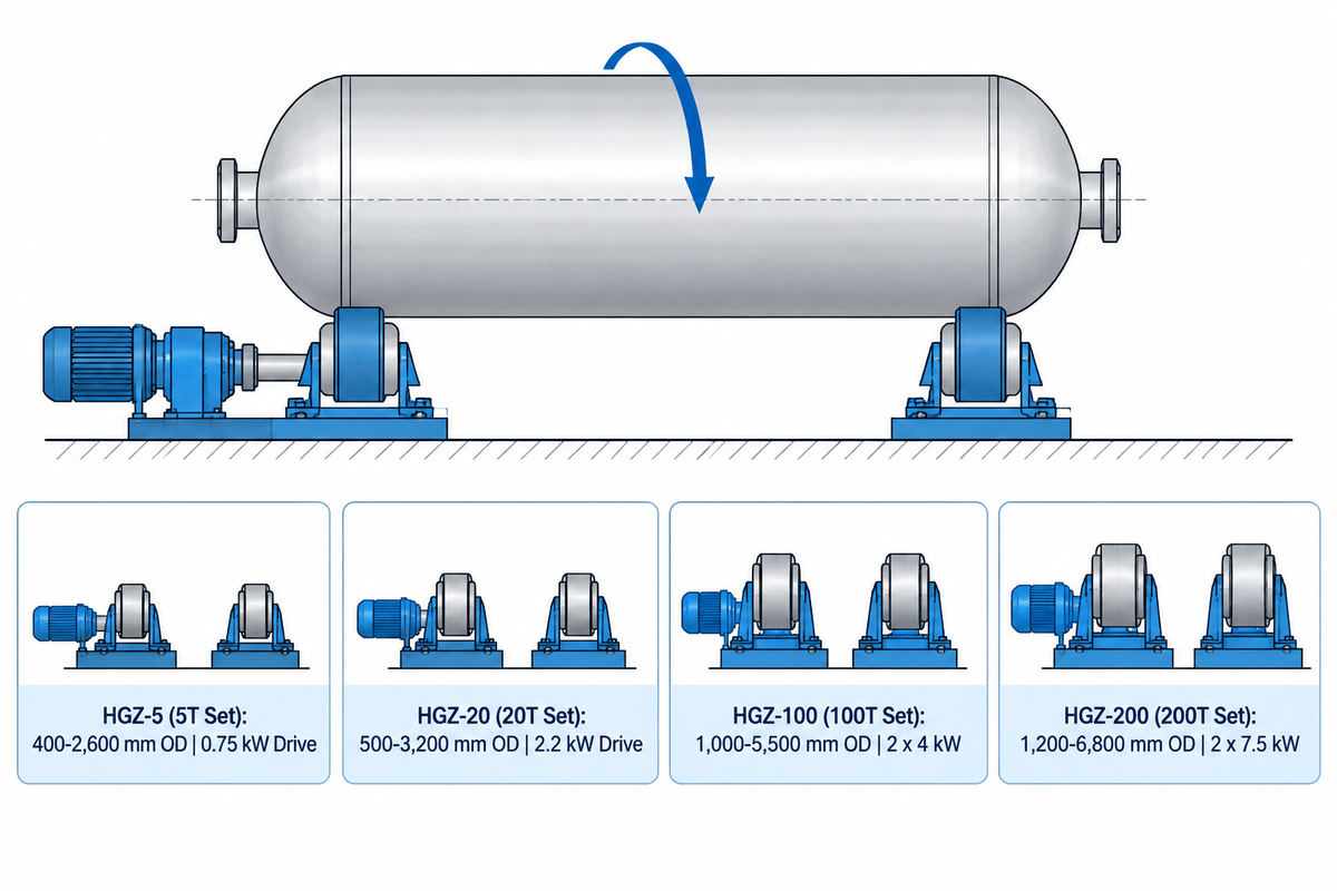
A tank rotator is used to maintain a constant circumferential weld speed of 100 to 1,000 mm/min (6 to 60 m/h) over varying shell diameters. It drives the workpiece through fixed-diameter friction rollers controlled by a stepless AC variable-frequency drive, per RESIZE welding rotator engineering specifications. Each standard system couples one powered drive bed with one unpowered idler bed.
When sufficient traction is attained to prevent slip, linear tangential speed of the vessel wall is equal to the peripheral speed of the drive roller wheel.
The linear surface speed of the vessel wall is expressed as: v_shell = pi × d_wheel × n_wheel = pi × D_vessel × N_vessel
In the above expression, d_wheel is the roller diameter in millimeters and n_wheel is the roller speed in revolutions per minute. A shop can switch from a 900 mm pipe spool to a 4,200 mm pressure vessel shell without recalculating gear ratios. Assuming no slip at the contact track, a conventional tank rotator will provide the same linear surface speed of 450 mm/min at the weld seam, if the roller peripheral speed is kept constant. Steady travel speed of the vessel helps weld quality and boosts shop productivity.
Consistent torque transfer requires adequate frictional traction at the roller-shell interface. As highlighted in The Fabricator’s guide to weld positioning, powered and idler turning rolls rotate pipes and cylinders for downhand welding. According to Aubrik’s welding rotator design data, turning roll capacities are in the range of 1 to 1,000 metric tons for standard and custom ZT/AD series. Its HGKF and ZDG fit up systems are capable of 2,000 metric tons. Within the RESIZE catalog, model ratings are represented by four HGZ self-aligning sets:
- The HGZ-5 (5T Set) supports vessel diameters from 400 mm to 2,600 mm using a 0.75 kW AC drive motor.
- The HGZ-20 (20T Set) rotates shells from 500 mm to 3,200 mm in diameter with a 2.2 kW drive package.
- The HGZ-100 (100T Set) handles pressure vessels from 1,000 mm to 5,500 mm using dual 4 kW synchronized motors.
- The HGZ-200 (200T Set) drives heavy cylindrical vessels from 1,200 mm to 6,800 mm with dual 7.5 kW motors.
Light 1-ton bench rollers such as Techtongda units serve thin packaging drums. Higher-tonnage welding turning beds select single- or dual-motor drivetrains based on load, torque, and synchronization requirements. Oily mill scale or oval courses can result in micro-slip between the roller tire and vessel wall. When rotational slip happens, heat input per millimeter is changed.
Conventional vs. Self-Aligning vs. Fit-Up Tank Rotators: Architecture Comparison
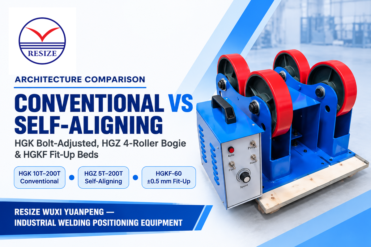
Fabrication shops select between conventional rotators, self-aligning welding rotators and hydraulic fit-up rotators based on three shop metrics. Daily changeover frequency of diameters and wall stiffness of the vessel Shell are evaluated as well as tack-welding alignment tolerances. A conventional unit uses Sliding roller Brackets with high tensile bolts or a manual lead screw. When there is a significant change in vessel diameters, the brackets need to be repositioned by Riggers and production is halted.
Meanwhile, a standard self-aligning welding rotator bed uses a pivoted two-roller bogie on each side of the frame, resulting in a total of four roller contacts. Lowering a cylindrical tank onto the bed swings the upper and lower rollers into contact. The bogies cradle the shell across its full diameter range without bolt adjustment, thereby improving production efficiency. For shops assembling shell courses, hydraulic fit-up rotators integrate four-directional lifting cylinders to align adjacent cans before root tacking. In a vendor-reported project documented by Aubrik on a 500 m³ storage tank, an HGKF-60 fit-up rotator cut per-section alignment from 8 hours to 45 minutes. The hydraulic bed ensured +- 0.5 mm joint concentricity, and resulted in 90% less weld rework.
Supplier catalogs position 6T to 50T self aligning rotators for mixed-diameter thin shells. Unheated thin stainless or aluminum tanks pair Shore 90A–95A polyurethane wheels with a 60° to 75° full included angle. However, as an engineering precaution on thin shells (such as diameter-to-thickness ratios D/t above 120) or out-of-round cans, engineers check local wall stiffness against concentrated bogie wheel loads. Internal spider stiffening rings or wide face conventional cradles help in eliminating local shell flexing along with self-aligning type bed.
| Model & Architecture Type | Diameter Adjustment Method | Rated Capacity & Speed Band | Best-Fit Fabrication Scenario | Limitation / Operating Boundary |
|---|---|---|---|---|
| HGK-10 Conventional Turning Roll (Bolt-Adjusted) | Manual bolt relocation across T-slot bed | 10T set (100–1,000 mm/min stepless VFD) | Batch production of identical carbon steel pipe or small vessel shells | Requires crane downtime to unbolt brackets when changing diameters |
| HGK-60 Conventional Turning Roll (Lead-Screw) | Hand-cranked lead-screw shaft moving carriages | 60T set (30T drive + 30T idler; 6–60 m/h) | Medium-to-heavy pressure vessel courses and heat-exchanger shells | Slower diameter changeover than hinged self-aligning bogies |
| HGK-200 Heavy Conventional Turning Roll | Modular bolt-locked heavy steel brackets | 200T set (100–1,000 mm/min; forged steel wheels) | Thick-wall boilers, preheated Cr-Mo reactors, and heavy drums | Two-wheel contact per side requires internal rings on thin walls |
| HGZ-5 Self-Aligning Rotator (Light Hinged Bogie) | Automatic 4-roller bogie swing (0.75 kW drive) | 5T set (400–2,600 mm diameter; 6–60 m/h) | Thin-wall stainless food tanks, light spools, and high-mix job shops | External longitudinal seam bars cannot pass smoothly over dual bogie wheels |
| HGZ-20 Self-Aligning Rotator (Medium Hinged Bogie) | Automatic 4-roller bogie swing (2.2 kW drive) | 20T set (500–3,200 mm diameter; 6–60 m/h) | Chemical storage tanks and multi-diameter pipe fabrication bays | Un-stiffened thin cans need internal spider rings to prevent ovality flex |
| HGZ-60 Self-Aligning Rotator (Intermediate Bogie) | Automatic 4-roller hinged bogie carriage | 60T set (30T drive + 30T idler; 6–60 m/h) | Mixed-diameter pressure vessels and medium industrial storage tanks | Verify single-bed 30T axle limit when rotating offset nozzle shells |
| HGZ-100 Self-Aligning Rotator (Dual-Motor Bogie) | Automatic 4-roller bogie swing (2 × 4 kW motors) | 100T set (1,000–5,500 mm diameter; 6–60 m/h) | Wind-tower cans and multi-course pressure vessels with frequent OD shifts | Polyurethane wheels capped at 80 °C–90 °C continuous contact temperature |
| HGZ-200 Self-Aligning Rotator (Heavy Bogie) | Automatic 4-roller bogie swing (2 × 7.5 kW motors) | 200T set (1,200–6,800 mm diameter; 6–60 m/h) | Large-diameter refinery columns and heavy cylindrical vessels up to 200T | Requires leveled shop floor or rail foundation within 0.5 mm/m |
| HGKF-60 Hydraulic Fit-Up Rotator (2+2 Alignment Bed) | 3D hydraulic lifting and lateral cylinders | 60T fit-up class (systems 20T–1,000T+; ±0.5 mm) | Shell-to-shell root alignment on 500 m³ storage tanks and wind towers | Dedicated to fit-up and tacking before transferring to standard turning rolls |
| 2-Axis Tilt-Rotate Schweißpositionierer (Chuck/Table) | 360° powered chuck rotation + tilt table | Fractional-ton to multi-ton chuck/table classes | Dished heads, hemispherical end caps, valve bodies, and short flanged spools | Unsuitable for long horizontal shells when load or gravity overturning moment exceeds rated table limits |
Can Welding Rotators Be Used With Positioners in the Same Fabrication Cell?
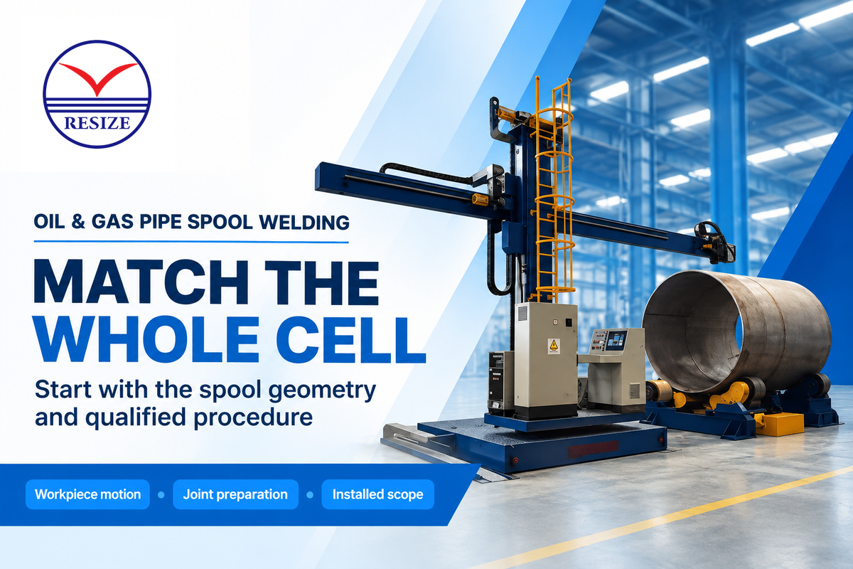
Yes, in fabrication shops, horizontal tank turning rolls are frequently paired with a single-axis headstock positioner or a 2-axis tilt-rotate positioner in the same welding cell. During dished-head-to-shell assembly, the positioner chuck controls axial thrust and rotation. Idler roller beds support the overhanging cylindrical shell.
According to the Surplus Record industrial welding equipment buying guide, multi-axis welding positioner cannot replace power tank turning rolls on long cylinders. Long shells rapidly exceed a positioner table’s overturning moment rating. In combined cells, coordinate or decouple the headstock drive and the rotator drive, so the motors do not oppose each other.
Tank Rotator Sizing Math: Calculating Load Capacity, Eccentric Margin, and Cradle Angle
Sizing a tank rotator strictly by the empty steel shell weight is the most common engineering mistake made in pressure vessel fabrication. Long and heavy manways, offset nozzle clusters, and internal trays and spiders also increase the shell weight and offset. That offset rapidly overloads one roller station.
To avoid wheel overload and drive stall, use two shop-floor design frameworks, the 4-Factor Traction-to-Tonnage Rule und the 60-Degree Cradle-Angle Sizing Benchmark. Actual drive motor power and gearbox reducer torque must also be verified against the measured center-of-gravity eccentricity and shell roundness shown on the vessel drawing.
According to the 4-Factor Traction-to-Tonnage Rule, an engineer calculates the required rotator capacity across four sequential checks.
- Calculate total wet or fit-up mass (W_max) by summing bare shell courses, dished heads, nozzles, internal stiffeners, and any ballast load on the rolls.
- Apply a traction safety factor of 1.3 to 1.5 (references to a 1.5 service factor are found in Cyclotron and Aubrik guides) to cover rolling friction, startup inertia, and climbing resistance caused by out-of-roundness.
- Apply an eccentricity and center-of-gravity offset factor of 1.25 to 1.40 to account for longitudinal weight shifts and for torque spikes due to offset manways.
- Compute minimum set tonnage as W_req = W_max × K_s × K_e, and verify that the heavier axle station stays within the single-bed structural rating.
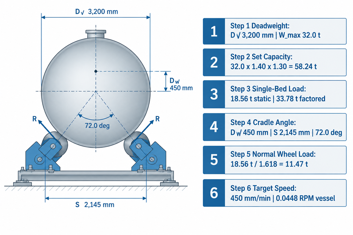
According to the 60-Degree Cradle-Angle Sizing Benchmark, the included angle (theta) between the two roller contact lines and the vessel center is found from three dimensions.
theta = 2 × arcsin ( S / (D_v + D_w) )
Static force equilibrium is shown in the Penn State Mechanics Map concurrent equilibrium analysis. The normal radial reaction force on each side of a two-roller cradle bed follows a non-linear trigonometric secant relation:
F_wheel = W_station / ( 2 × cos(theta / 2) )
Here, W_station is the vertical load carried by one two-roller conventional cradle bed. A four-roller self-aligning bed splits that side reaction across the two rollers of each pivoted side bogie. For a symmetric two-roller cradle under static load, increasing theta from 60° to 90° raises each side’s normal reaction from 0.577 to 0.707 times the bed load. That ratio is 0.630 at 75° and reaches 0.872 to 1.000 at 110° to 120° (a 73.2% increase from 60° to 120°). To 120 deg. (a 73.2% increase from 60 deg. To 120 deg.). Below 45 deg., the horizontal support base narrows, and lateral tipping risk increases. Keeping theta in the 60 deg. To 90 deg. Range (within 45 deg. To 110 deg.). Keeping theta in the preferred 60° to 90° zone (within the 45° to 110° operating window) balances lateral stability and wheel reaction forces alongside shell stiffness and drive torque checks.
| Calculation Step | Input Parameter / Formula | Calculated Value | Engineering Selection Decision |
|---|---|---|---|
| 1. Vessel Geometry & Static Weight | Shell OD D_v = 3,200 mm; Total mass with heads & manway W_max = 32.0 t | 32.0 metric tons deadweight | Reject a 30T set because the vessel exceeds its rated load; reject a 35T set because it falls below the calculated 58.24 t selection requirement. |
| 2. Required Set Capacity (4-Factor Rule) | W_req = W_max × K_s (1.40) × K_e (1.30) | 58.24 metric tons | Select a 60T or 80T rotator set depending on single-bed eccentric allocation. |
| 3. Heavier Axle Station Load (W_station) | Illustrative uneven span: nozzle-end bed carries W_station = 18.56 t static reaction | 18.56 t static (33.78 t factored) | The drive bed carries less than its 30T static rating, but applying the 1.40 × 1.30 sizing factors puts required single-bed capacity at 33.78 t (above 30T), requiring an 80T set (40T per bed) or a third support bed. |
| 4. Included Cradle Angle (theta) | Roller OD D_w = 450 mm; Center spacing S = 2,145 mm; theta = 2 × arcsin(2145 / 3650) | 72.0 degrees included angle | Falls squarely inside the optimal 60°–90° cradle stability benchmark. |
| 5. Secant Normal Wheel Load (F_wheel) | F_wheel = 18.56 t / (2 × cos(36°)) = 18.56 / 1.618 | 11.47 metric tons static normal load per side | Select wheel assemblies whose per-wheel radial load rating exceeds the factored side reaction. |
| 6. Target Vessel & Roller RPM | SAW travel speed v = 450 mm/min (27 m/h); N_vessel = 450 / (pi × 3200) | 0.0448 RPM vessel (0.318 RPM roller) | Shell surface speed is 450 mm/min (0.0448 RPM vessel speed at 3,200 mm OD); verify motor speed and gearbox ratio for this operating point. |
How Many Idler Roller Stands Do Long Cylindrical Tanks Need to Prevent Sagging?
Long cylindrical tanks require 2 or more Idler roller stands when one drive bed and one Idler bed would exceed allowable shell deflection or bed load limits. Engineers fix the exact number of stands and the spacing from vessel wall thickness, section modulus, attachment weights, and bending stiffness.
When three or more roller beds support a single rigid cylinder, any floor height variation across the bay can unload one idler and overload the adjacent bed. For long pipe welding rotator configurations, specify hydraulic load-equalizing bogies or synchronized dual-drive sets.
Welding Rotator Speed Calculation, Control Panel Interfaces, and Manual Torch Synchronization
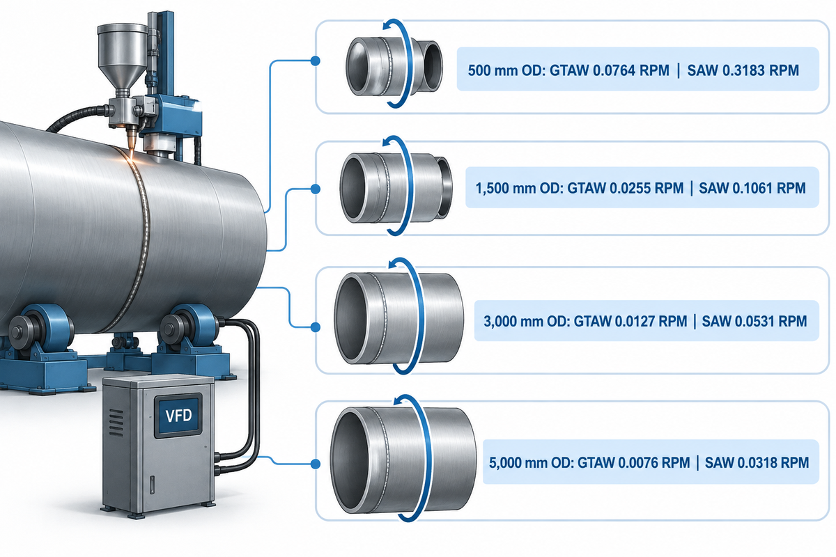
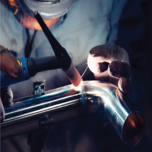
Stable weld bead geometry requires that the surface speed of the welding rotator be directly matched to the heat-input travel speed of the welding process. A welder may hold a manual torch for a root pass, or an operator may run a tandem submerged arc head. In both cases, the control panel must regulate linear shell speed smoothly over a 10:1 turn-down ratio.
Standard RESIZE conventional and self-aligning rotators provide a stepless variable speed range of 100 to 1,000 mm/min (6 to 60 m/h). Lower motor speeds result in less cooling airflow from shaft-mounted fans, and an independent blower fan maintains cooling. Available low-speed torque and smooth rotation are governed by motor and gearbox characteristics as well as closed-loop vector drive settings.
| Vessel Outer Diameter (D_v) | GTAW / Manual Root Pass (120 mm/min / 7.2 m/h) | GMAW / FCAW Fill Pass (300 mm/min / 18.0 m/h) | Single-Wire SAW Girth Seam (500 mm/min / 30.0 m/h) | Tandem SAW High-Deposition (800 mm/min / 48.0 m/h) |
|---|---|---|---|---|
| 500 mm (20 in.) | 0.0764 RPM | 0.1910 RPM | 0.3183 RPM | 0.5093 RPM |
| 1,500 mm (59 in.) | 0.0255 RPM | 0.0637 RPM | 0.1061 RPM | 0.1698 RPM |
| 3,000 mm (118 in.) | 0.0127 RPM | 0.0318 RPM | 0.0531 RPM | 0.0849 RPM |
| 5,000 mm (197 in.) | 0.0076 RPM | 0.0191 RPM | 0.0318 RPM | 0.0509 RPM |
To automate girth welding cells, the main electrical control box should include three hardware interfaces:
- A Digital speed control panel provides a direct speed readout in mm/min or m/h using LED or HMI, allowing the operator to set the speed before striking an arc.
- An operator pendant, foot switch, or wireless control provides forward/reverse jog, speed pot, emergency stop, and manual torch on/off control.
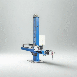
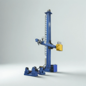
- A PLC interface provides synchronization for industrial analog or fieldbus terminals to connect to a Column-and-boom pipe welding manipulator.
Roller Wheel Material Selection for Pipe, Cylindrical Vessel, and Tank Welding
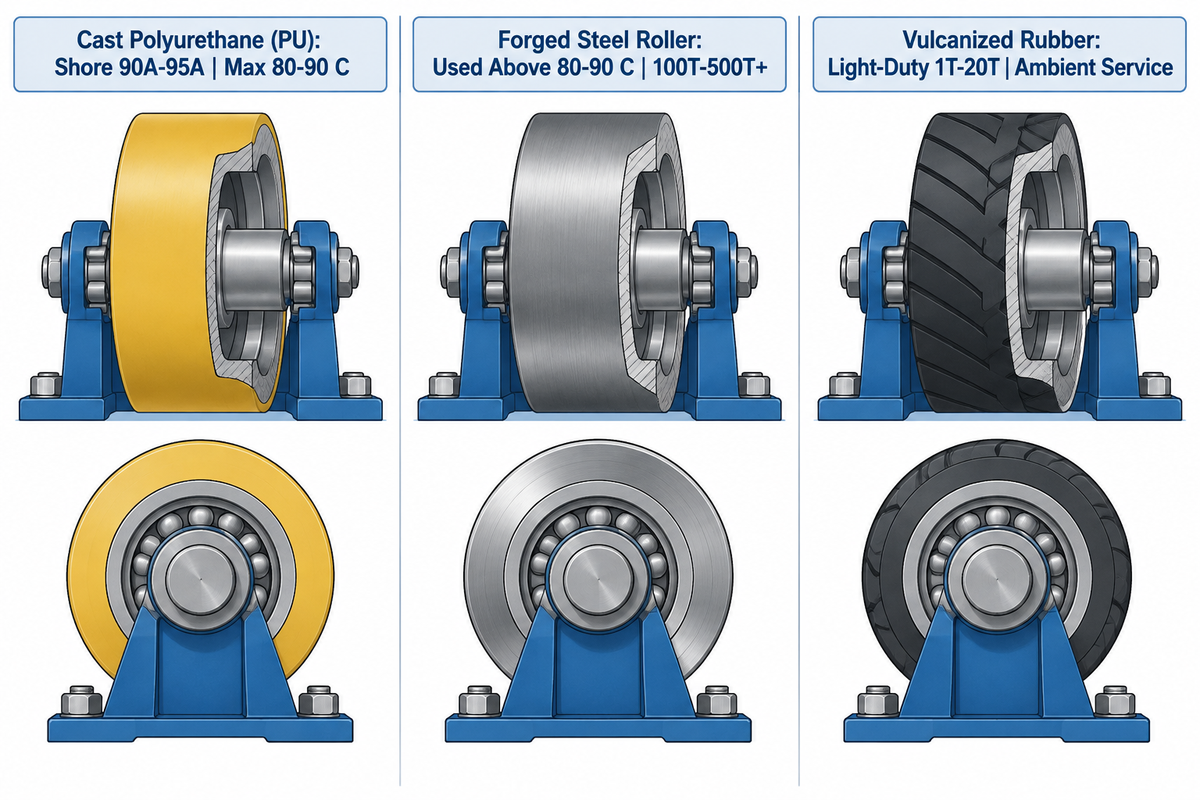
Choosing the wrong roller tire material contaminates corrosion-resistant alloy shells or destabilizes wheel bond during high-temperature weld preheat. Fabricators choose roller material and elastomer durometer based on three variables: unit line load, surface finish, and weld preheat temperature.
Clean polyurethane-tired rollers (Shore 90A to 95A hardness) give high dry traction on stainless steel, aluminum, titanium and sanitary food-grade tanks. Working within their load and temp ratings helps to maintain surface finish during post-weld pickling and polishing. Shop machinists note in Practical Machinist discussions on rolling precision rings, that urethane compression provides positive drive with no marring on thin-gauge rings. For lighter pipe rotators for welding small pipe spools and pipelines, vulcanized rubber tires also provide good traction at shop ambient temps. However, rubber tires have a shorter life due to oil and ozone degradation when compared to cast polyurethane tires.
For heavy-duty carbon steel pressure vessels, offshore wind towers, and thick-walled, preheated shells, rollers made from induction-hardened forged alloy steels, provide good resistance to contact stress and long life. Compare the three industrial wheel materials for the following engineering parameters:
| Wheel Tire Material | Hardness & Core Construction | Surface Traction & Grip Profile | Thermal Operating Boundary | Primary Vessel & Pipe Application |
|---|---|---|---|---|
| Cast Polyurethane (PU) | Shore 90A–95A elastomer bonded on steel core | High non-marring friction grip; isolates stainless from carbon-steel pickup | Up to 80 °C–90 °C (176 °F–194 °F) continuous track temp per Aubrik guide | Stainless steel tanks, thin-wall aluminum vessels, painted pipe, high-traction drive beds |
| Induction-Hardened Forged Steel | Induction-hardened forged steel roller | Metallic line contact; lower dry friction than PU so tracks must stay clean | Used above 80 °C–90 °C (176 °F–194 °F) wheel-track preheat | Heavy-duty pressure vessels (100T–500T+), preheated Cr-Mo shells, thick carbon steel boilers |
| Vulcanized Industrial Rubber | Vulcanized elastomer bonded on steel hub | High compliant grip for light-duty ambient pipe rotation | Ambient shop service below polyurethane thermal limits | Light-duty small pipe fabrication (1T–20T) without oil contamination or weld preheat |
What Wheels Can Be Used for Tank Rotators When Preheat Exceeds 100 °C?
When circumferential weld preheat exceeds 100 °C (212 °F), fabricators use forged steel rollers whenever contact-track temperatures exceed the 80 °C to 90 °C elastomer rating. Alternatively, shops position polyurethane roller beds away from the heated zone so contact-track temperatures and loads remain within the tire and bond ratings. Above the elastomer bond limit, the adhesive between cast polyurethane and the steel core degrades and can delaminate under radial load.
If a stainless or clad vessel requires localized preheat above 100 °C near a girth seam, offset polyurethane beds from the heated band. For polyurethane beds, wheel-track temperatures must be kept below the tire’s rated temperatures to not break the bond. Keeping wheel-track temperature within the tire rating protects the bond, and an infrared pyrometer reading on the track confirms that the surface stays below 80 °C before rotation.
Stopping Axial Spiral Creep in Welding Tank Turning Rolls: Anti-Drift Systems and Welder Grounding Rules
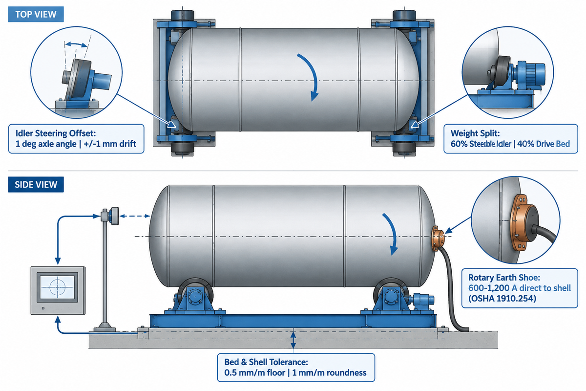
Axial spiral creep, or “vessel walking,” occurs when a rotating cylindrical tank migrates lengthwise along the turning rolls like a screw thread. Even a misalignment of 0.1 degree between the drive and idler roller axles creates a continuous axial velocity component. Over a four-hour submerged arc pass, the shell walks tens of millimeters, pulls the groove away from the torch, and risks dropping off the beds.
According to US Patent US8342493B2 (Anti-Drift Turning Roll System), the patented anti-drift system relies on four mechanical parameters:
- An idler axle steering offset places each idler roller on an axle with about a 1-degree offset angle relative to the pivot axis. Corrective steering force is created as a result of this offset.
- In the patent’s Table 1 example, a recommended weight distribution places about 60% of workpiece weight on steerable idler rollers and about 40% on drive rollers. This weight distribution keeps steering responsive while preserving drive traction.
- Closed-loop drift control uses an optical or mechanical edge sensor to detect end-face movement. It steers the idler axles to hold axial drift within ±1 mm.
- According to the patent’s Table 1 specification, the workpiece is smooth and round within 1 mm per meter of diameter. Aubrik design guidelines also specify leveling roller beds within 0.5 mm/m across the floor.
Bearing and operator safety are just as important on welding tank turning lines. OSHA 29 CFR 1910.254 (Arc Welding and Cutting) governs arc-welding ground return and frame grounding safety. As an engineering best practice to protect rotator bearings, the welding machine return clamp should never be attached to the rotator frame. The welding work-return lead should be attached to the workpiece instead. When 600 A to 1,200 A submerged arc current returns through roller shafts, it arcs across the thin oil film inside rolling bearings. As documented in the SKF Bearing Failures and Prevention Manual, stray electric current creates micro-craters (confirmed under 500× to 10,000× magnification) and corrugated raceway fluting. That electrical erosion rapidly degrades rotator bearings. Install a high-amperage rotary ground clamp or copper earth shoe riding directly on a cleaned vessel shell band.
Also, shop safety audits must enforce three federal OSHA requirements and enforcement guidance items around rotating vessels.
- Guard rotating nip points under OSHA 29 CFR 1910.212(a)(1) (with hazardous-energy enforcement context in OSHA Directive CPL 02-00-147) so physical barriers block access to the shell-to-roller nip point. Any presence-sensing mats must connect to safety-rated controls at a safe stopping distance.
- Lockout/Tagout of Hazardous energy shall be enforced under OSHA 29 CFR 1910.147 (a), as pendants are control circuit devices, not energy-isolating devices. Lockout the main disconnect, bleed hydraulic pressure, and chock the eccentric shell, then move the bracket.
- The storage of oxygen cylinders, as covered in OSHA 1910.253, requires that such cylinders be stored at least 20 ft (6.1 m) from fuel gas cylinders or from combustibles. A compliant noncombustible fire barrier is an allowed alternative, while OSHA 1910.254 covers arc welding equipment.
| Observed Shop Symptom | Primary Root Cause | Quantitative Diagnostic Check | Corrective Engineering Action |
|---|---|---|---|
| Vessel walks steadily toward one end during rotation | Drive and idler bed centerlines are skewed or floor foundation slopes lengthwise | Measure axle alignment and bed elevations against specified alignment tolerances, distinguishing total elevation difference from slope per meter | Re-align beds with a cross-line laser; shim low brackets or activate 1° anti-drift steering idler |
| Vessel creeps forward and backward once per revolution | Out-of-round shell course or proud longitudinal weld seam bumping over rollers | Shell ovality alters roller contact and causes cyclic axial movement (US8342493B2 cites 1 mm/m roundness for its anti-drift setup) | Install internal spider stiffening rings before rotation; grind external tack seam flush at roller tracks |
| Drive rollers spin while heavy vessel stalls | Eccentric nozzle/manway load exceeds drive torque or oily shell reduces friction | Check motor current draw and calculate CG torque against 4-Factor Rule | Degrease roller tracks; add counterweight opposite heavy manway or switch to Shore 90A–95A PU drive wheels |
| Audible rumbling in roller bearings during service | Stray SAW welding current arcing through roller bearings to shop earth | Inspect raceways for corrugated fluting (500×–10,000× cratering per SKF criteria) | Remove ground clamp from frame; install a 600–1,200 A rotary copper earth shoe directly on the vessel shell |
Tank Rotator Cost Tiers, Lead Times, and OEM Procurement Checklist
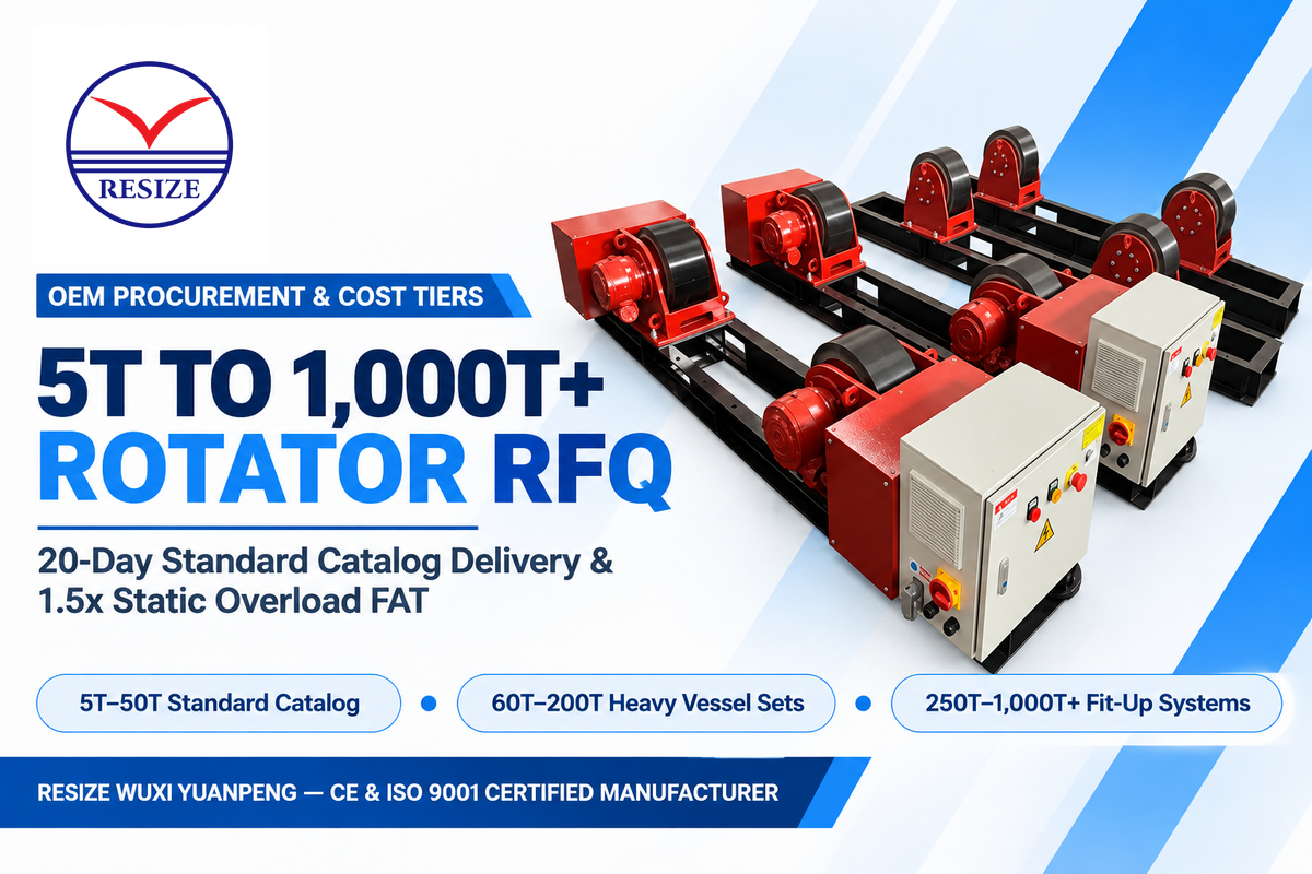
Industrial tank rotator pricing and factory lead times are dependent on tonnage tier, frame architecture, wheel metallurgy, and control automation. Fabricators in the Eng-Tips pressure vessel manufacturing equipment forum say capital budgets for a heavy vessel turning roll and idler set are between USD 50,000 to USD 100,000 in North American vessel shops. Standard sets are less expensive for simple shop use. Custom closed-loop anti-drift packages, motorized rail bogies, and voltage transformers alter bill-of-materials cost significantly. Therefore, exact unit pricing and delivery schedules require a formal RFQ matched to your vessel drawing.
| Capacity & Architecture Tier | Typical Vessel Envelope | Primary Engineering Cost Drivers | Factory Lead Time Basis | Commercial Pricing Basis |
|---|---|---|---|---|
| Standard Catalog Sets (5T – 50T Conventional / Self-Aligning) | Diameter 400–4,000 mm; standard shop pipe & storage tanks | PU vs steel wheels, AC VFD configuration, pendant option, 380V/480V 3-phase input | 20-day catalog delivery benchmark (Waldun reference); custom voltages quoted per order | Project quotation per model (1D+1I set vs extra idlers) |
| Heavy-Duty Vessel Sets (60T – 200T HGZ / HGK Series) | Diameter 1,000–6,800 mm; thick-wall ASME pressure vessels & wind towers | Forged steel wheels, dual synchronized AC vector drives, reducer torque rating, rail bogies | Project-scheduled based on forged wheel machining and gearbox selection | Project quotation per vessel weight, CG eccentricity & rail gauge |
| Custom Fit-Up & Anti-Drift Systems (250T – 1,000T+) | Large-diameter multi-course reactors, offshore tower cans & 500 m³+ storage tanks | Hydraulic fit-up cylinders, closed-loop anti-drift steering idlers, custom environmental enclosure | Scheduled per custom engineering design and hydraulic build scope | Custom engineering quotation per vessel general arrangement drawing |
Engineering RFQ Specification Checklist for Buying a Tank Rotator
5.
The following seven engineering parameters must be included in your purchase inquiry to obtain comparable quotes for compliant equipment.
- State the set versus single-bed tonnage basis in the purchase specification. The quotation should list both the combined 1 Drive + 1 Idler set rating (such as 60T) and each bed’s structural rating (such as 30T).
- State the minimum and maximum vessel diameters so the roller center spacing keeps the full included cradle angle in the range of 60° to 90° for all the shells.
- Provide eccentricity and protrusion sketches, showing heavy nozzles, manways or stiffening rings which require increased roller clearance or eccentric drive torque.
- Define wheel material and maximum wheel-track temperature by specifying Shore 90A–95A polyurethane for shells below 80 °C–90 °C or induction-hardened forged steel above 80 °C–90 °C.
- State the required linear speed band (100–1,000 mm/min or 6–60 m/h) and the manipulator interface signals for automated girth welding.
- State the shop electrical supply and environmental ratings, including 380 V or 480 V 3-phase power, IP65 enclosure protection where required, and an OSHA 1910.147 lockable disconnect.
- Factory acceptance test (FAT) documentation covering static load test reports, such as Aubrik’s reported 1.5× static overload test, verification of low-speed stability, and roller axle alignment checks should be provided before shipment.
Which Manufacturers Supply Heavy-Duty Tank Turning Rolls and How Should Buyers Evaluate OEMs?
Major global suppliers of heavy-duty tank turning rolls include Koike Aronson, Pemamek (PEMA), Key Plant Automation, LJ Welding Automation, and RESIZE (Wuxi Yuanpeng Machinery Equipment Factory). Buyers analyze these manufacturers by assessing set and individual bed rating capacity, reducer torque, material of the wheels, and factory overload tests.
When comparing global welding rotator manufacturers, review whether the supplier matches frame section modulus and drive torque to your vessel drawing. At RESIZE (Wuxi Yuanpeng Machinery Equipment Factory), our HGZ and HGK catalog series span 5T to 500T, while industrial rotator offerings extend from 30T to over 1,000T capacity. Every unit is backed by precision VFD speed control and CE / ISO 9001 quality certifications.
2026 Tank Welding Outlook: Closed-Loop Speed Verification (ISO 17662) and Optical Anti-Drift Automation
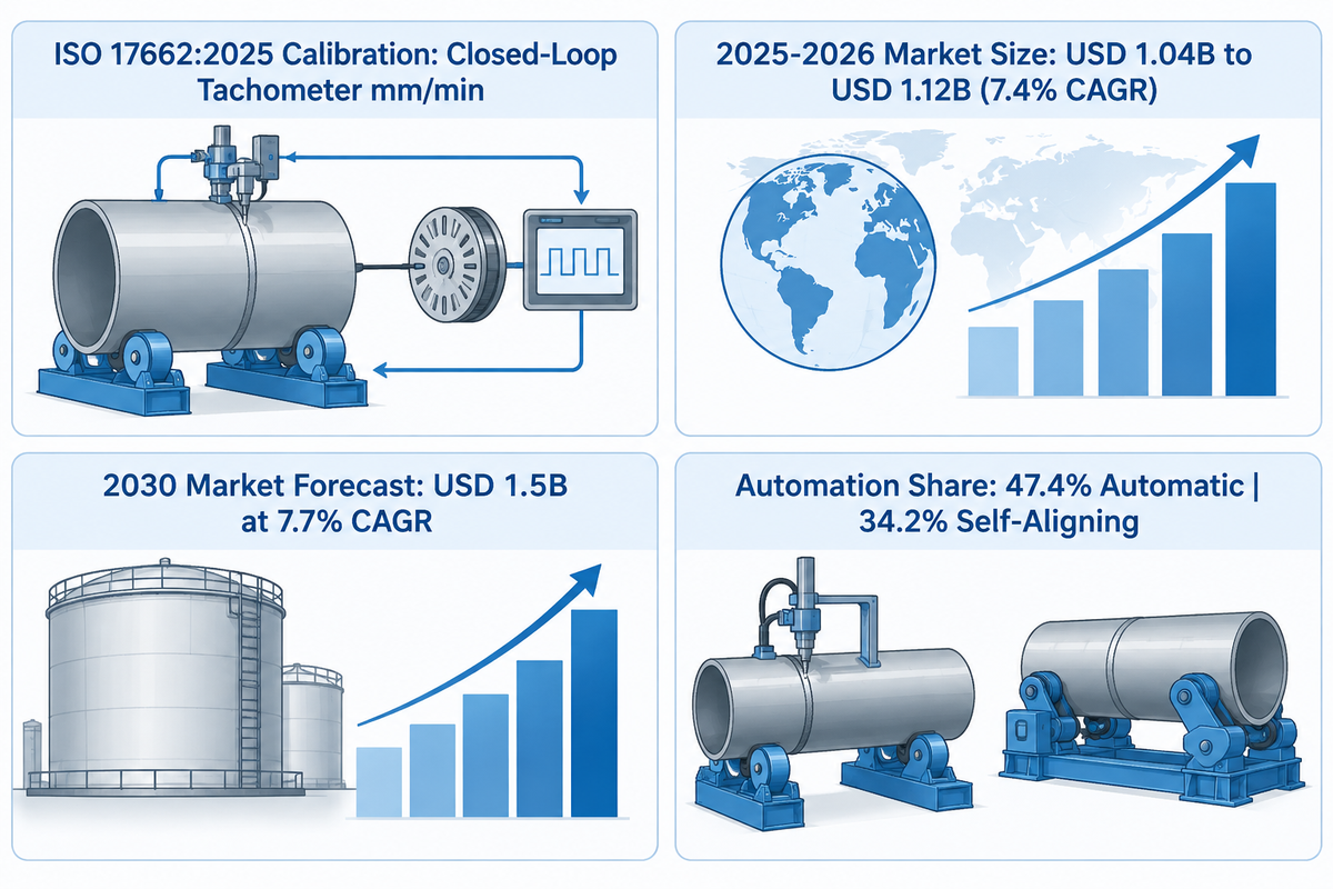
Two technical developments shape how pressure vessel and wind-tower fabricators manage tank rotators in 2026. First is the updated edition of ISO 17662:2025 (which superseded ISO 17662:2016), specifying requirements for calibration, verification, and validation of equipment used for welding and ancillary activities. The second is increasing adoption of automated and anti-drift turning roll cells.
Engineers must note the standard’s exact boundary. As explained in Therness’s engineering review of ISO 17662, it governs in-service production monitoring and calibration of process-control equipment such as travel-speed drives. Different sets of codes govern new equipment factory certification and final weldment NDT acceptance. Open-loop VFD frequency (Hz) alone misses real shell travel-speed drift when polyurethane tires compress or slip on scaled plate. Adding an external workpiece-contact surface speed tachometer or encoder helps quality teams verify true linear travel speed in mm/min during ISO 17662 calibration checks.
Adoption of automated and anti-drift roller beds is also increasing rapidly in heavy energy fabrication. A 2026–2030 Global Pipe Welding Rotators Market Outlook (supported by OpenPR industry study data) estimates the global market to increase from USD 1.04 billion in 2025 to USD 1.12 billion in 2026 (a 7.4% CAGR). The same outlook projects that the market will reach USD 1.5 billion by 2030 at a 7.7% CAGR. Separate industry research from Grand View Research estimates that automatic operation accounted for 47.4% of 2025 market revenue. Self-aligning rotators held a 34.2% product share as shops reduce manual crane re-centering stops.
Häufig gestellte Fragen
What is the difference between a self-aligning tank rotator and a conventional welding rotator?
A self-aligning tank rotator uses hinged four roller bogies that automatically adjust to vessel diameters from 400 mm to 6,800 mm.
Meanwhile, a conventional welding rotator employs a two-roller cradle with bolt or lead-screw spacing. Self-aligning beds simplify diameter changes in high-mix shops, while either design can mark or deform a thin shell when concentrated roller loads exceed its local load-bearing capacity.
How do you stop a cylindrical tank from walking or creeping axially on turning rolls?
Stop axial tank creep by leveling the drive and idler beds within 0.5 mm/m and aligning all roller axles parallel to the vessel centerline.
In the anti-drift system of US Patent US8342493B2, the vessel is kept round within 1 mm per meter of diameter. The patent describes limiting axial movement to ±1 mm by steering a 1-degree offset idler axle.
Should tank rotator load capacity be sized by deadweight or drive traction torque?
Tank rotator structural capacity must accommodate maximum operating vessel weight and bed distribution, while drive torque and traction must be checked for eccentricity.
In our 4-Factor sizing model, maximum vessel weight is multiplied by a 1.3 to 1.5 traction safety factor and a 1.25 to 1.40 eccentricity factor. The preferred 60-degree to 90-degree cradle angle helps manage stability and wheel reaction loads, though inadequate drive torque or oily tracks can still cause stalling.
Can one tank rotator drive unit power multiple idler roller stands for long pipes or wind towers?
Yes, one drive bed can rotate a long pipe or wind tower across two or three idler stands within its rated drive torque.
Level all idler beds within 0.5 mm/m across a bay and ensure relative elevations across stands are not such that one high roller bed overloads an axle.
Why do welding rotator roller bearings fail prematurely when submerged arc welding heavy vessels?
Welding rotator roller bearings fail prematurely when welding current returns through the rotator frame and bearings instead of a dedicated workpiece return lead.
High-amperage submerged arc current (600–1,200 A) arcs across the bearing oil film. This current creates microscopic discharge craters (confirmed at 500× to 10,000× magnification per SKF analysis) and corrugated raceway fluting. OSHA 29 CFR 1910.254 addresses arc welding grounding safety, and a dedicated rotary ground shoe on the vessel routes welding current back to the power source without passing through rotator bearings.
How do you verify whether a supplier’s tank rotator tonnage rating covers the full set or only one bed?
The supplier’s quotation and nameplate drawing are required to state both the combined 1 Drive + 1 Idler set rating and single-bed limit.
A 60T vessel load gives 30T per bed only when equally distributed between two beds, whereas an offset center of gravity produces unequal reactions. With an off center load, the reactions are unbalanced and approach the allowable limits of the combined set and individual beds.
Referenzen und Quellen
- The Occupational Safety and Health Administration (OSHA) – 29 CFR Part 1910 Subpart Q: Welding, Cutting and Brazing (1910.254 Arc Welding and Cutting)
- The Occupational Safety and Health Administration (OSHA) – Directive CPL 02-00-147: The Control of Hazardous Energy & 29 CFR 1910.212(a) Machine Guarding
- The Occupational Safety and Health Administration (OSHA) – 29 CFR 1910.147: The Control of Hazardous Energy (Lockout/Tagout)
- International Organization for Standardization (ISO) — ISO 17662:2025: Welding — Calibration, Verification and Validation of Equipment Used for Welding, Including for Ancillary Activities (superseding ISO 17662:2016)
- USPTO / Google Patents – US Patent US8342493B2: Anti-Drift Turning Roll System (1° Idler Offset & 60/40 Weight Split)
- SKF Group Engineering Library – Bearing Failures and their Causes: Electrical Erosion, Raceway Fluting, and 500×-10,000× Crater Inspection
- Pennsylvania State University – Mechanics Map: 2D Concurrent Force Equilibrium
- The Fabricator / FMA Communications – 5 Things Welders Need to Know About Weld Positioners and Turning Rolls
- Therness Engineering — ISO 17662 (2025 Revision): Welding Monitoring, Calibration, Verification, and Validation
- Aubrik Welding Automation – Welding Rotator Design Parameters (1 to 1,000 Metric Ton Turning Roll Specifications)
- Aubrik Welding Automation – Welding Rotators & Turning Rolls: HGKF-60 500 m³ Storage Tank Fit-Up Case Data
- Surplus Record Industrial Machinery Guide – Welding Positioners vs. Power Tank Turning Rolls Buying Guide
- Practical Machinist Engineering Forum – Urethane Compression Drive Mechanics on Precision Sheet Metal Rings
- Eng-Tips Pressure Vessel Engineering Forum – Pressure Vessel Manufacturing Equipment Capital Cost Benchmarks
- GlobeNewswire / Research and Markets – Pipe Welding Rotators Market 2026-2030 & OpenPR Market Study Summary