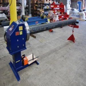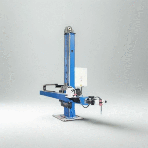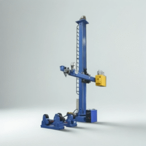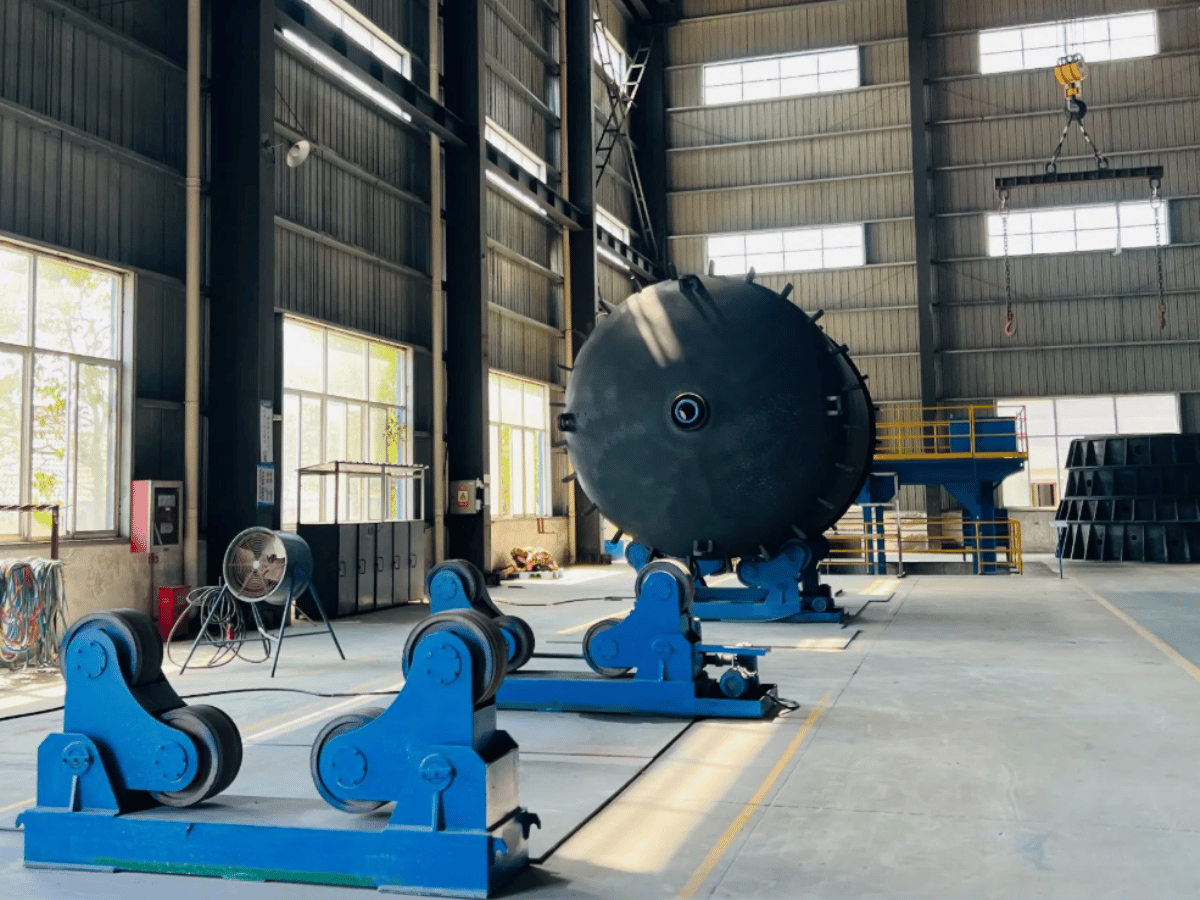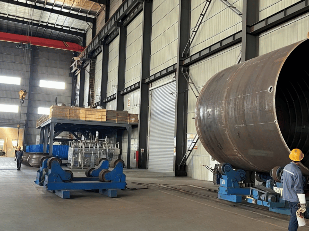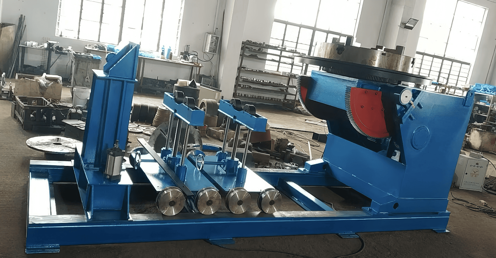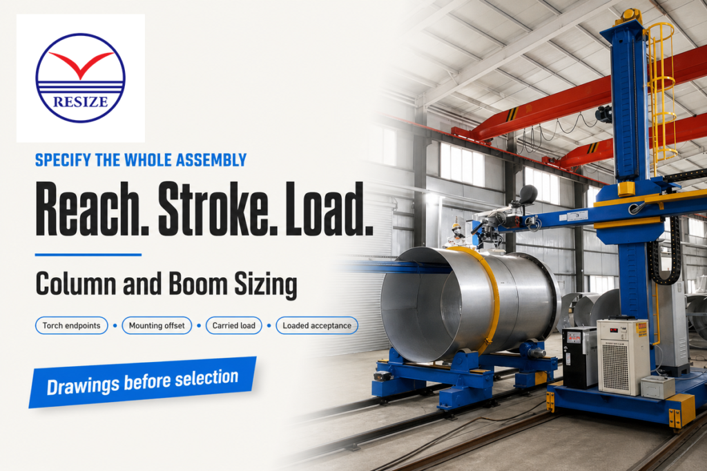
A column and boom welding manipulator supports and places the welding head either above or beside a workpiece. Size it for torch positions, travel, and the total load carried at the outreach. Next, check the installation envelope and prove the motion under load.
By GW · Updated October 2026
A machine can have enough stroke yet miss the lowest joint. A head can fit the quoted payload yet overload the allowed mounting arrangement. Begin with a dimensioned fabrication layout and an attachment list before choosing a boom manipulator model.
Read reach, stroke, and working height separately
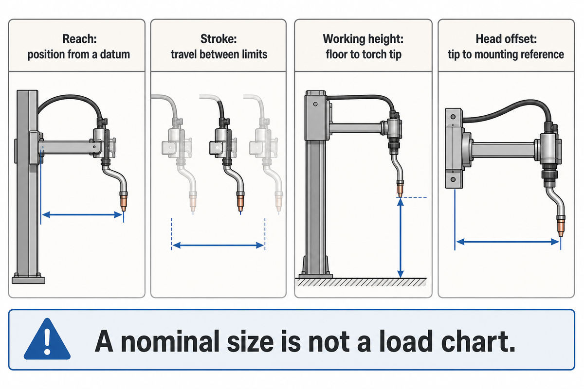
Reach is a position relative to a specified datum. Stroke is travel between limits. Working height is the torch tip’s height above the finished floor; the tip may sit above or below the boom reference line. Nominal sizes such as 4 m by 4 m require a drawing to support a purchase decision.
Supplier terminology varies. Label the column centerline and finished floor and the mounting point of the head on the same drawing. With the welding heads installed, request the minimum and maximum positions. Keep the boom and column dimensions, the diameter of the workpiece, and the distance needed to load it separate.
| Dimension | Record on the drawing | Example or required confirmation |
|---|---|---|
| Nominal size | Meaning of each catalogue number | 4 m by 4 m is a label until defined |
| Minimum torch reach | Closest usable tip position from column datum | 1.10 m in the horizontal example |
| Maximum torch reach | Farthest usable tip position | 3.70 m in the horizontal example |
| Horizontal stroke | Change in boom reference position | 2.60 m before approach/retraction allowance |
| Head offset | Tip position relative to mounting reference | 0.25 m forward in the horizontal example |
| Minimum working height | Lowest usable tip above floor datum | 0.90 m in the vertical example |
| Maximum working height | Highest usable tip above floor datum | 3.40 m in the vertical example |
| Vertical stroke | Change in saddle reference height | 2.50 m before other required movements |
| Swept and parked envelope | Rear boom, cables, head and moving base | Supplier drawing; no universal clearance |
Dimension definitions are a buyer worksheet, not a load chart. For a broader introduction to machine types, see the overview of small welding manipulators. Keep this drawing review focused on the seams your shop must reach.
3-Check Torch Envelope Review
Prior to selecting a manipulator, a 3-Check Torch Envelope Review is performed to ensure that required tip positions are within available travel, and approved by the supplier for loading.
Plot boom reach against every weld seam
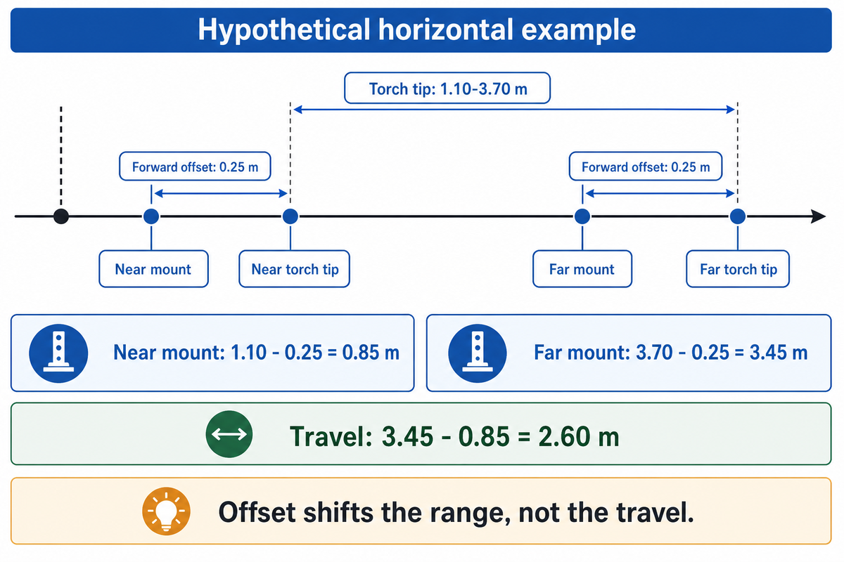
Boom reach must extend the entire length of the weld path and approach. Plot the farthest and nearest torch positions from one column datum, and account for head mounting offset. Consider internal access, withdrawal and nearby structures. Endpoints don’t guarantee unobstructed path following by the loaded assembly.
For a longitudinal tank seam, draw the vessel wall, opening and end closures in plan. Include the welding torch body, cross slides and camera brackets. A tip that reaches a joint on paper isn’t very useful if the feeder or boom can’t pass through the opening.
Horizontal example: a fixed offset moves both endpoints
Assume the seam runs from 1.10 m to 3.70 m from the column datum. The fixed head places the tip 0.25 m ahead of the mounting reference. Subtract this offset from both the tip positions:
- Near mounting position: 1.10 m − 0.25 m = 0.85 m.
- Far mounting position: 3.70 m − 0.25 m = 3.45 m.
- Required movement between those positions: 3.45 m − 0.85 m = 2.60 m.
The fixed offset changes the two endpoints, not their difference. Adding another 0.25 m to the stroke would count the offset incorrectly. Withdrawal and approach movements are separate inputs; base them on the proposed arrangement and not a borrowed clearance.
The geometry of head articulation changes for each joint and torch position. Repeat the check for each torch angle, joint and fixture position. The supplier should overlay the entire moving assembly, including cables, on your layout to confirm the loaded path. Hold the order if the return drawing proves only maximum reach.
A 2.60 m stroke doesn’t describe a 3.70 m torch reach. The example needs a mounting range of 0.85 to 3.45 m and the stated 0.25 m offset. A different column position, or a different head mounting arrangement, requires a new coordinate check even when the travel span is the same.
Check column travel from the lowest joint to the highest
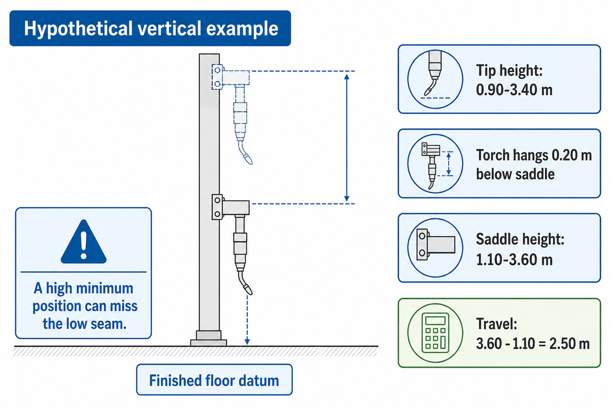
When the workpiece supports and head are installed, column travel must place the torch at the lowest required joint and at the highest required joint. Check the two working-height limits from the finished floor. A large vertical stroke can still start too high, and sufficient maximum height can conceal an inaccessible low seam.
Suppose the required tip heights are 0.90–3.40 m, and the torch hangs 0.20 m below the saddle reference. The saddle must reach 1.10–3.60 m: add 0.20 m to each tip height. Saddle travel is 3.60 m − 1.10 m = 2.50 m. Again, a fixed offset shifts the range without enlarging it.
Use the actual roller bed elevation. A pipe with a different diameter may change the joint height on the same turning rolls. See the support geometry with the welding rotators for the workpiece. Their roll adjustment and workpiece rating address different questions from manipulator travel.
Clearance for the crane hook, lifting attachments and access for loading must also appear on the elevation drawing. Don’t subtract them from a nominal column height without considering the physical arrangement. Procurement must also await the lowest-tip position and the tallest-machine dimension.
The 0.90 m joint is the limiting low position in this example. A saddle which stops above 1.10 m can’t reach it with the stated 0.20 m hanging offset. Verify the endpoints of the supplier drawing before regarding 2.50 m of vertical travel as a sufficient amount.
Verify boom capacity with the complete welding head load
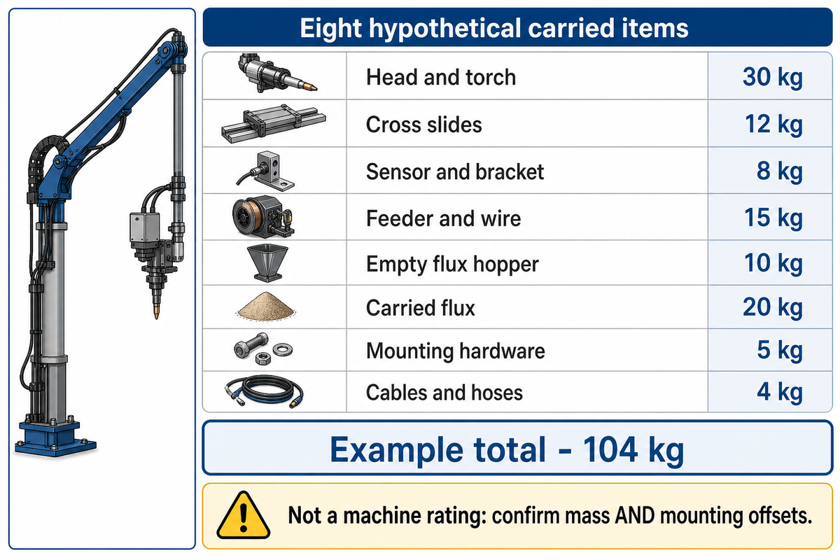
Boom capacity must account for every item carried at its actual mounting location and extension. Provide masses, offsets and the expected operating conditions. A head nameplate alone doesn’t indicate slides, feeders, brackets and consumables. An approved load arrangement by the supplier is required because equal total masses can impose different moments on the supporting structure.
What is the significance of boom capacity in small welding manipulators?
Boom capacity defines the permitted carried load under the conditions stated by the equipment supplier. Small welding manipulators still require complete attachment schedules and mounting drawings. Without reference to the load reference point, boom position and included equipment, a capacity figure doesn’t help a buyer judge if a welding assembly fits the rating.
| Item carried by the boom | Example mass | What the supplier needs |
|---|---|---|
| Welding head and torch | 30 kg | Mounting face and center of gravity |
| Cross slides | 12 kg | Travel and extreme offset |
| Tracking sensor and bracket | 8 kg | Location through adjustment range |
| Wire feeder and carried wire | 15 kg | Mount location and wire routing |
| Empty flux hopper | 10 kg | Support point and dimensions |
| Maximum carried flux | 20 kg | Maximum fill condition |
| Additional mounting hardware | 5 kg | Actual bracket arrangement |
| Carried cables and hoses | 4 kg | Supported share plus routing forces |
| Total example mass | 104 kg | Approved loading at required outreach |
These hypothetical masses sum to 104 kg. They don’t establish a suitable 104 kg machine rating, a reserve factor or an allowable bending moment. Replace every entry with actual supplier data. Identify loads at the boom end separately from equipment near the column or at the opposite end; don’t subtract one mass from another as a capacity calculation.
In The Fabricator’s submerged arc welding guidance, Paul Rieder and Ryan Holt of LJ Welding discuss overhead support for the hopper, head and wire spool. This example supports the compilation of attachment schedules; it doesn’t provide a RESIZE load rating. For a MIG welding manipulator, be sure to capture the feeder, cable pack and any wire supply carried by the structure.
How does welding head stability affect the welding process?
Welding head stability affects how consistently the torch keeps its relation to the joint. Deflection, vibration or motion after a direction change can disturb alignment. Set a loaded demonstration at the required outreach and weld travel speed, with agreed measurements, instead of accepting an unloaded movement test as evidence of weld quality.
Record the worst mounting offset and consumable fill state on the acceptance sheet. Ask how the stated positioning precision is measured under these conditions. The workpiece positioning equipment must carry the part separately. A positioner or rotator rating in tonnes says nothing of the boom’s allowed head load. Longer travel, a heavy-duty label and a higher total machine weight can’t stand in for the missing load conditions.
Compare standard, telescopic, and rail-mounted column booms
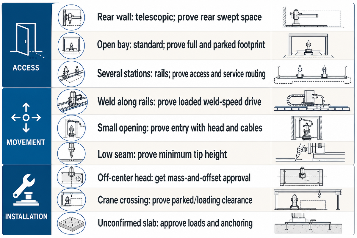
A standard boom, a telescopic boom and a rail-mounted system solve different layout problems. Compare their operating, parked and loading envelopes on the same floor plan. Telescoping can reduce rear space, while rails move the column between locations. Neither solves the problem of checking head clearance, foundation and service line routing.
| Shop condition | Option to investigate | Required proof or limitation |
|---|---|---|
| Rear wall close to the column | Telescopic boom | Entire rear swept envelope; less space does not mean zero |
| Open bay and one weld station | Standard boom | Full-extension footprint and parked position |
| Several stations in a row | Rail-mounted column | Travel limits, station access and service routing |
| Long seam parallel to proposed rails | Rail travel during welding | Drive approved for weld speed and loaded motion |
| Small vessel opening | Slim head and suitable boom section | Entry path with slides, sensor and cables fitted |
| Low seam near the support bed | Lower working-height arrangement | Minimum tip height and support interference |
| Heavy off-center head assembly | Revised mount or rated larger structure | Written mass-and-offset approval |
| Overhead crane crosses the bay | Defined parked/loading arrangement | Crane and machine envelopes do not conflict |
| Unconfirmed slab or rail support | Installation design review | Loads, anchoring and support drawings before order |
A track system can serve more than one station. The Fabricator’s DME brewing-equipment case shows one example of a system that serves five stations. That’s a layout example from a different company, not from RESIZE. It doesn’t show that rail travel can replace the perpendicular reach needed inside your vessel.
Fixed systems also require a supporting-structure assessment. The U.S. general-industry rule states:
“Machines designed for a fixed location shall be securely anchored to prevent walking or moving.”
Get the machine supplier to provide foundation loads and anchoring requirements, and then get the supporting structure checked by the plant’s responsible designer. Rail alignment, end stops and other support details need their own approved design. An unresolved floor or rail design is a stop sign to purchase, even if the boom fits the room.
Set inspection and acceptance conditions before ordering
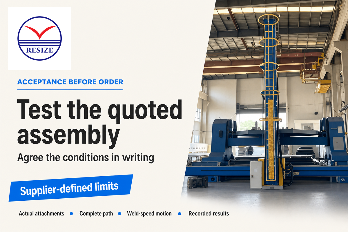
Acceptance means the supplied assembly reaches the agreed positions and moves as required with its actual load. State the joint, torch angle, speed and consumable status prior to the test. Agree on the measurement techniques and criteria to be accepted in the contract, as a demonstration without limits can’t prove a future performance case.
Supplier screening may be aided by public information. PEMA publishes endpoint ranges, and LJ publishes model load figures; our review also found conflicting LJ stroke figures between a family table and a model page. Verify critical design loads and travel by requesting a revision-controlled drawing. Public information for RESIZE, likewise, requires specifying a configuration envelope and load limits for acceptance.
- Review the supplied assembly. Match the head, slides, brackets and services to the approved load schedule.
- Traverse the complete path. Check low, high, near and far positions, including approach, withdrawal and changes of direction.
- Test the intended welding motion and behavior at low speeds. Verify stops and restart logics with the process and controls agreed for the job.
- Record the result. Retain readings, test conditions and corrective actions against the signed acceptance sheet.
A supplier should state any permitted deflection and positioning tolerance for that build; this guide sets no universal millimeter limit. For a pressure vessel, the applicable construction code and welding procedure are separate decisions. The American Welding Society’s D1.1/D1.1M:2025-AMD1 page concerns structural steel welding. It isn’t proof of boom capacity or a substitute for the required vessel code.
Maintenance and adjustment access should also be included in the review. Under the conditions covered by OSHA 1910.147, control of hazardous energy, servicing requires appropriate energy isolation, including stored energy. A stop button does not isolate energy. How is the raised assembly supported? How is it isolated by authorized personnel? You need to answer these before starting covered work.
Reject a test that alters the purchase conditions. If the order uses the illustrative 104 kg attachment set at the far mounting position of 3.45 m, an unloaded pass close to the column cannot confirm that requirement. Actual acceptance limits must come from the approved machine and welding specification.
Request a documented RESIZE manipulator configuration
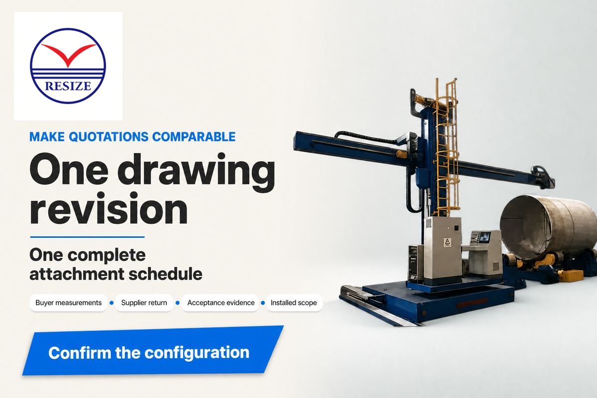
A good useful RESIZE quote request combines the seam layout, complete load schedule and acceptance conditions in a single revision. You should solicit a dimensioned return drawing and request an explicit rating for the proposed assembly. The public product range is a starting point; unpublished tip-load and mounting conditions still require written confirmation from the supplier.
Read about RESIZE’s company background, and send the worksheet with the process and workpiece drawings. The brand’s public pipe-manipulator card lists travel up to 8,000 mm, but that maximum does not establish your minimum reach, working height or loaded performance. No configuration-specific tip-load value was verified for this guide.
You should ask the supplier to return the scope and acceptance record in the final two columns, and enter your actual measured values in the request for quotation. The numeric values shown are for illustrative purposes only.
| Parametru | Recommended range / buyer input | Why it matters / supplier return | How to verify |
|---|---|---|---|
| Torch reach | Example 1.10–3.70 m | Return tip and mount endpoints from shared datum | Signed envelope drawing |
| Working height | Example 0.90–3.40 m | Return low and high limits with head installed | Elevation drawing and test |
| Head mounting | Example 0.25 m forward offset | Confirm actual center of gravity and bracket | Approved mounting drawing |
| Carried load | Example inventory 104 kg | Return permitted loading at stated outreach | Load approval and loaded test |
| Weld travel | Enter required mm/min and duty cycle | Confirm which axis is rated for welding motion | Representative weld trial |
| Workpiece support | Enter mass in kg and dimensions in mm | Separate support rating from manipulator load | Support layout and rating |
| Installed services | Enter voltage, phase and utility needs | Name responsibility for cables, extraction and interfaces | Site checks and integration test |
| Commercial scope | List delivery and installation inclusions | Separate foundations, commissioning, training and spares | Itemized quote and acceptance terms |
The quoted price can be compared only if the returned scope matches. The budget owner should see the cost of supporting equipment and the cost of installation and commissioning separately from the base price of the machine. Ask for the cost of an unresolved option rather than assuming it is included. Avoid approving a quote where acceptance responsibility or the load rating remains blank.
Integration and utility requirements for welding automation
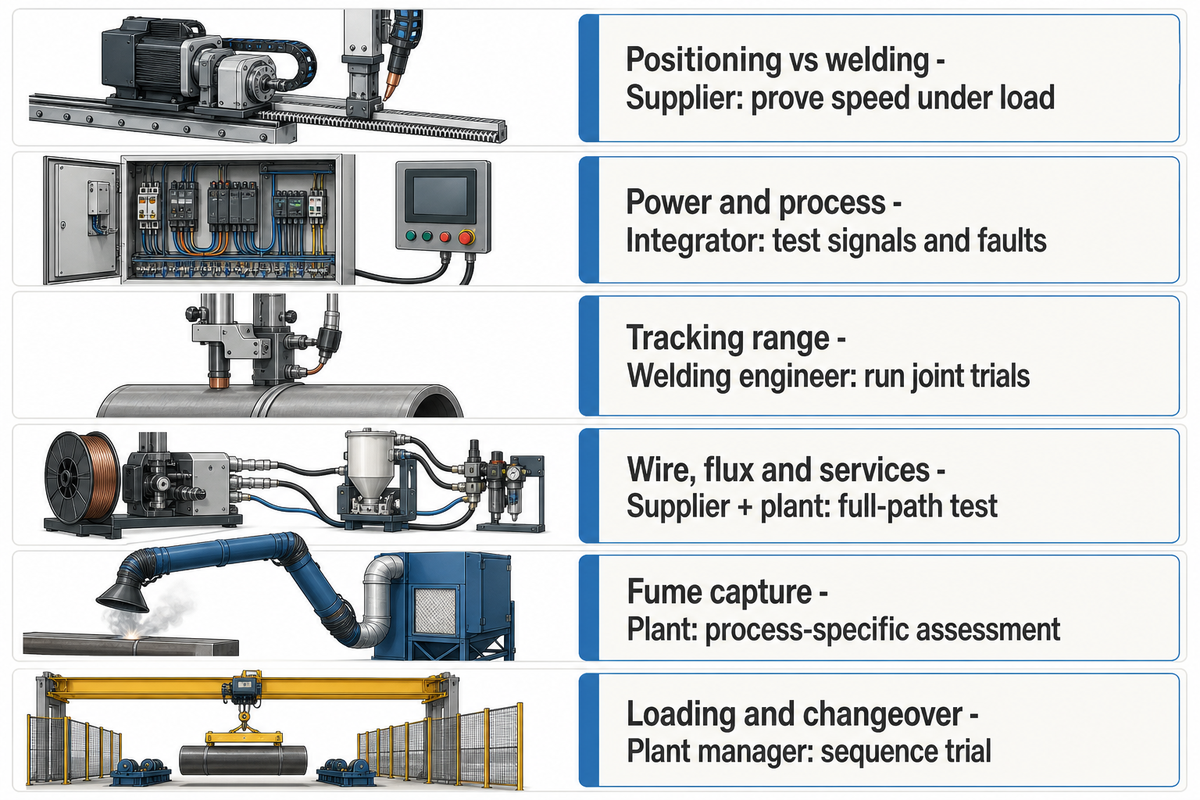
Welding automation relies on integrated movement, process control and plant services. Verify which axis moves the head and which drives the weld. Examine the power supply, wire or flux system, return circuit and fume collection across the complete path. A manipulator system that can jog into position may require other controls for continuous welding.
What role does the power supply play in small welding manipulators?
The power supply for welding establishes the output and must communicate correctly with process motion and operator controls. Check the duty cycle, start and stop signals, fault responses and connections. The electrical installation and the welding return circuit need a qualified assessment; the manipulator structure cannot be presumed to provide an adequate path for welding return current.
Arc-welding apparatus is addressed by OSHA 1910.254. For system scope, AWS lists D16.2M/D16.2:2021 as a guide covering robotic and automatic arc-welding installations, including MIG, TIG, plasma arc and flux-cored processes. It provides background information to assist in the consideration of integration questions; it does not approve a system.
Assess extraction at every working position. OSHA 1910.252(c) on welding ventilation distinguishes room, material and confined-space conditions. A hood placed for one seam is not evidence of effective capture at another; the plant’s responsible specialist must select and verify the arrangement.
If you are going to automate several welding processes, define each recipe separately. A MIG column setup and submerged arc equipment, for example, have different consumables and interfaces. Programmable or CNC control alone does not prove a robotic capability, seam tracking or compatible control systems. Ask exactly what the quoted controller can command and monitor.
Track productivity using good welds and downtime, and not travel speed alone. Higher MIG deposition rates cannot compensate for poor fit-up or a blocked loading sequence. A repeatable setup reduces rework only when it holds the required process conditions. Have the welder record cycle times, operator fatigue and recurring rework issues during trials before making an uptime or output forecast.
Frequently Asked Questions About Sizing
Can small welding manipulators be used for automatic pipe welding?
Small welding manipulators can support automatic pipe welding when their envelope, head load and controls match the joint and support arrangement.
How do column and boom welding manipulators improve welding accuracy?
A column and boom welding manipulator can make head positioning more repeatable when the assembly and process are correctly specified.
What accessories and options are available for small welding manipulators?
Available accessories and options may include cross slides, seam tracking, cameras, feeders, flux equipment and powered travel.
What is a weld manipulator?
A weld manipulator supports or moves the welding head relative to the workpiece.
What types of welding systems can use small welding manipulators?
Suitable manipulators can carry equipment for MIG welding, TIG welding, submerged arc welding and other specified processes.
Does a longer boom always carry more weight?
A longer boom does not establish a higher allowable payload.
How should I compare column and boom welding manipulator prices?
Compare quotes against the same approved envelope, load schedule, controls and installed scope.
Send your plan, elevation and attachment schedule via the RESIZE welding manipulator product page. Request a return drawing that confirms both travel endpoints, the approved loading and the installation scope before you select a machine.
Method note: This guide synthesizes publicly available manufacturer information with the named standards and trade sources below which were verified in October 2026. Worked dimensions and masses are illustrative. They are not RESIZE test results or approved machine ratings. The supplier and responsible plant specialists must verify the actual design and acceptance conditions.
Referințe și surse
- The Fabricator, Thinking About Submerged Arc Welding, by Paul Rieder and Ryan Holt
- The Fabricator, Better Brewing Through Automation, by Rob Colman
- Occupational Safety and Health Administration, 29 CFR 1910.212, Machinery and Machine Guarding
- American Welding Society, D1.1/D1.1M Structural Welding Code, Steel, 2025-AMD1
- Occupational Safety and Health Administration, 29 CFR 1910.147, Control of Hazardous Energy
- Occupational Safety and Health Administration, 29 CFR 1910.254, Arc Welding and Cutting
- American Welding Society, D16 Committee, Published Documents
- Occupational Safety and Health Administration, 29 CFR 1910.252, General Welding Requirements