![Biselado y biselado: Guía de preparación de bordes industriales [2026]](https://resizeweld.com/wp-content/uploads/2026/04/0-1024x683.webp)
A reference guide for engineers, fabricators and procurement teams. Supports AWS, ASME, API and ISO specifications along with an 8-joint bevel decision matri× you won’t find on competing pages.
Quick Specs: Beveling and Chamfering
| Common bevel angle range | 15° to 75° (single side); 30°, 37.5°, 45° most prevalent in industrial weld prep |
| Common chamfer angle | 45° symmetrical (also 30° and 60° for special tool geometries) |
| Governing standards | AWS D1.1 (structural), ASME B31.3 / B16.25 (process piping), API 1104 (pipelines), ISO 9692-1 (international weld prep) |
| Cut-quality standard | ISO 9013:2017 — perpendicularity tolerance Range 1 (tightest) through Range 5 |
| Equipment angle accuracy | CNC ±0.5° · Portable electric ±1° · Pneumatic ±1-2° · Manual ±2-3° |
| Wall-thickness rule of thumb | ≤6 mm single bevel · 6-15 mm V-groove · 15-40 mm J-prep · >40 mm compound or U-groove |
| Cost penalty for poor edge prep | Up to 84% increase in weld metal usage (Reddy, 2014) |
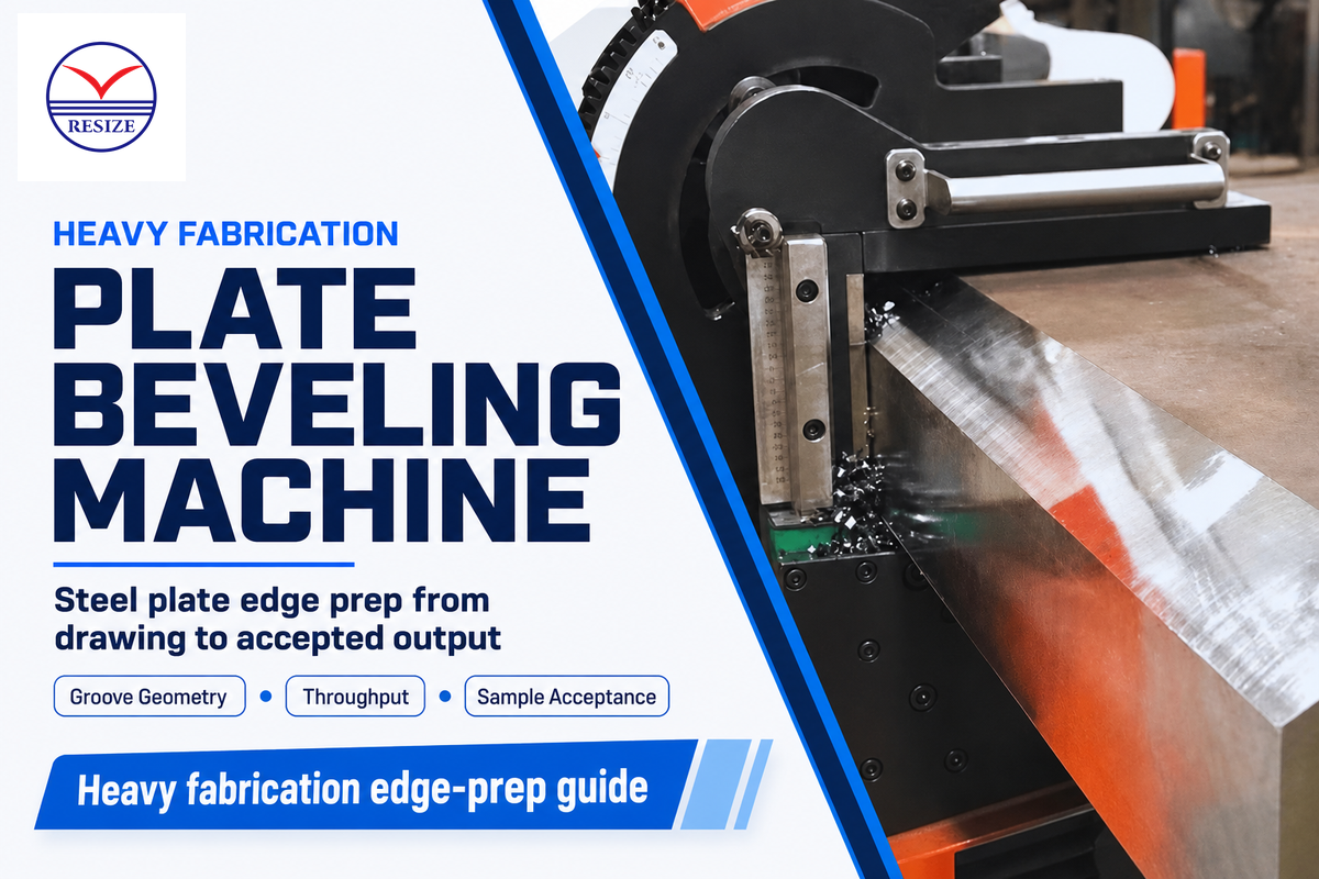
Beveling and chamfering both remove a (typically) 90 edge by cutting an angled surface, but the two are not interchangeable. Failing to understand the difference between the two can cost you money: welders applying the wrong groove geometry can end up adding 84% more filler metal to a weld joint (Reddy, 2014), and a single confusion between bevel angle and included angle can delay an entire pipeline construction schedule by weeks.
This decision matri× combines standards, joint geometry, tool accuracy and material knowledge that is critical to fabrication shops, pipeline contractors and CNC machine shops. It’s designed as a quick reference: the decision rules and tables are to be revisited, not read once.
What’s the Difference Between Beveling and Chamfering?
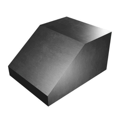
Chamfer removes a sharp 90 edge. Bevel reshapes an edge. Misuse of either approach costs you weld penetration. One easy-to remember statement sums up the everyday engineering issue involved, but let’s examine the shape details behind it.
A chamfer is a symmetrical, flat cut that joins two surfaces normally executed at 45 to remove a sharp 90 corner that could be damaged or could cause injury or a fastening failure in some other way. A bevel is a sloped cut that can extend the full thickness of a plate or pipe width, and can be angled anywhere from 15 to 75 from a perpendicular angle. ISO 9692-1:2013– an international standard for weld joint preparation- optimistically considers bevel as a purely structural shape requirement, while leaving out chamfer geometry entirely as part of its edge-finishing process.
The same general purpose guides both processes: to convert a sharp 90 edge that fails in service into a controlled shape that the next step can reliably build on. While the two shapes may be used interchangeably if you plan your design accordingly, they are more often found side-by-side in shop drawings: a 45 bead chamfer ready for a bolt hole, a 30 bevel bead for the weld that’s coming after.
| Dimension | Chafre | Bisel |
|---|---|---|
| Geometry | Flat, symmetrical, two surfaces meeting at fixed angle | Sloping edge, may be asymmetric, often through-thickness |
| Typical angle | 45° (also 30°, 60° for tooling) | 15°-75° (most often 30°, 37.5°, 45°) |
| Material removed | Small portion of edge only | Removes more material; can be the full edge length |
| Primary purpose | Safety, assembly lead-in, aesthetics, deburring | Weld joint preparation, structural fit, pipe end prep |
| Always cut? | Yes — chamfer is a machined feature | No — bevel can also be a forming feature (cast, rolled) |
| Governing standard | ASME Y14.5 dimensional notation | ISO 9692-1, AWS A2.4, ASME B16.25 (weld geometry) |
How to interpret the chart: don’t forget that every chamfer is a bevel, but not every bevel is a chamfer. Chamfering is a well-defined, small-angle, small-depth bevel used for edge finishing; beveling is a broader term that covers weld preparation, structural changes, and visual design. That difference in terminology ceases to matter when the shape reaches its final destination.
Specifying “chamfer” on a print usually places limits on the leg length (for instance, “0.5 45”). When “bevel” is called out, the dimensional restriction is on the included angle, which can be combined with a root face callout for added control. Read the feature call out before selecting the tool – the minor variation in terminology can make a difference in the final cut.
Standard Bevel Angle and Chamfer Angle Values (15°-75°)
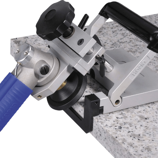
There is no “standard” bevel angle. Required angle is dictated by the welding code in use, the qualified welding procedure (WPS), and the wall thickness. Simply cutting 37.5 on every joint because that’s “what we always do” is how prequalified work fails an inspector – not infrequently.
Bevel Angle vs Included Angle: The $50,000 Misread
Bevel angle is the angle measured on one side of the cut. Included angle is the total angle of the V-groove formed between two beveled edges, from the original sharp 90 corner to the full open prep. A 37.5 bevel angle creates a 75 included angle (37.5 2). When a drawing states “75 groove”, the intention may be either the included angle, or the bevel angle on each side. A reading error will either double or halve the prep – precisely the mistake responsible for the well-known story of a $200,000 pipeline contract rework, after the shop cut 37.5 on each side of an API 1104 joint, which called for 30 per side. Always confirm with the drawing owner: bevel angle or included angle?
| Código | Bevel angle | Tolerancia | Root face | Notes |
|---|---|---|---|---|
| ASME B31.3 | Per WPS | Per WPS | Per WPS | References ASME B16.25 for end-prep geometry |
| ASME B16.25 | 37.5° | ±2.5° | 1.5 mm typical | Standard wall thickness ≤22 mm |
| AWS D1.1 CJP | 45° | ±5° | 0-3 mm | Prequalified joints, Table 3.4 |
| AWS D1.1 PJP | 30° min | ±5° | — | Partial joint penetration |
| API 1104 mainline | 30° | ±5° | 1.6 mm ±0.8 | Cross-country pipeline construction |
| API 1104 facility | 37.5° | ±2.5° | 1.6 mm ±0.8 | Tie-ins, station piping |
The 30-37.5-45 Bevel Angle Triad
Looking across the four major welding codes, three bevel angles account for 70% of all industrial weld prep:
- 30 – pipeline mainline (API 1104), partial joint penetration (AWS D1.1)
- 37.5 – process piping (ASME B16.25), pipeline tie-ins, pressure-vessel butt welds
- 45 – structural steel CJP (AWS D1.1), thin sheet welding, general fabrication
Choose from the three angles first. Only diverge when the WPS, wall thickness, or process (orbital GTAW, narrow-gap SAW) requires it.
5-Step Bevel Angle Selection Checklist
- ✔
Identify the appropriate code (AWS D1.1, ASME B31.3, API 1104, or ISO 9692-1). - ✔
Read the WPS and the print in conjunction. Verify every angle, root face, and root opening. - ✔
Identify whether the print specifies a bevel angle (one side) or an included angle (both sides combined). - ✔
Check the tolerance. ASME Section IX specifies re-qualification for groove-angle decreases exceeding 5. - ✔
Double check the bevel using a gauge after the cut – at 12, 3, 6, and 9 o’clock positions on pipe.
Weld Bevel Joint Types: 8-Joint Decision Matrix
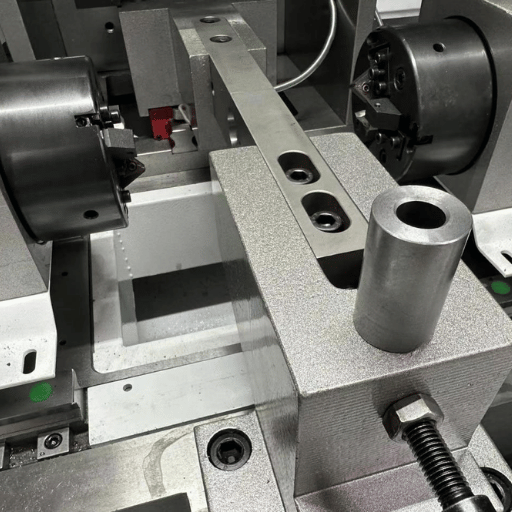
“What bevel joint type should I use?” is an entirely different question from “what bevel angle.” The joint type – single bevel, double bevel, single V, double V, J, U, flare bevel, fillet – must be selected based on wall thickness, access, residual-stress tolerance, and required filler consumption. AWS A2.4:2020 recognizes all eight as distinct welding symbols; ISO 9692-1:2013 outlines the geometry for each across arc welding processes.
| Joint type | Geometry | Wall thickness | Typical angle | Common process | When to choose |
|---|---|---|---|---|---|
| Square (no bevel) | 90° edge, gap only | ≤3 mm | N/A | GTAW, GMAW | Thin sheet, fillet welds, low-stress joints |
| Single bevel | One side beveled | 3-12 mm | 30°-45° | SMAW, GMAW | Access from one side only |
| Single V | Both sides beveled, V-groove | 6-20 mm | 37.5° per side (75° included) | SMAW, GTAW, GMAW | General fabrication, pipe butt welds |
| Double V | V groove on both faces (X-shape) | 15-40 mm | 30°-37.5° per side | SAW, FCAW | Two-side access, lower distortion than single V |
| Single J (J-prep) | Curved root, narrow groove | 15-40 mm | 15°-25° (sidewall) | GTAW, SMAW | Reduces filler 30-40% vs single V on heavy wall |
| U-groove | Curved root, both sides | ≥25 mm | 10°-20° sidewall | SMAW, SAW, FCAW | Heavy wall, pressure vessels, lowest filler use |
| Flare bevel | Curved member meets flat or curved member | Varía | Per AWS A2.4 | GMAW, SMAW | Tube-to-plate, rebar, structural angles |
| Compound bevel | Two angles on one prep (steep + shallow) | ≥25 mm | 37.5° root + 10° sidewall | GTAW root + SMAW fill | High-pressure piping, balances access and filler |
📐 Engineering Note
Groove width is proportional to wall thickness tan(bevel angle). For a 8 mm wall and a 37.5 bevel: 8 tan(37.5) 8 0.767 6.1 mm groove width per side, 12.2 mm included. Switching to a J-prepare on the same 8 mm joint typically subtracts 30-40% of that volume, which explains why thick-wall suppliers specify J-prepare for 15+ mm walls even where access enables a V.
Does the part need to be welded or used for load-bearing applications?
If the answer is in the affirmative, then the bevel is a load bearing feature – not a finish. Joint geometry must enable the welder to reach the root, fused both side walls, and give no lack-of-fusion weld defects to fail ultrasonic or radiographic inspection. Bad edge prep is far from cosmetic; a 2014 research paper published through ResearchGate showed that poor edge prep can increase your weld metal consumption by a whopping 84%, with the secondary consequence manifesting itself in residual stress and distortion (Reddy, 2014).
For load bearing, structural joints following AWS D1.1, fillet alone is rare for over 6 mm most code-required joints need a CJP groove weld with specified bevel.
AWS D1.1 views a weld made without backing or back gouging as not prequalified. That has been pointed out by engineers on Eng-Tips several times. The seemingly small detail of dropping back gouging from a single-V joint could cause the work to move out of prequalified and into procedure qualification.
Pipe vs Plate Edge Preparation
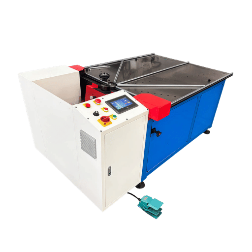
Plate beveling runs in a straight line. Pipe beveling is circumferential, the same angle has to be maintained all around the circumference, and the ID and OD limit access. Codes separate on this basis: API 1104 deals with pipeline pipe; AWS D1.1 steel plate.
| Aspecto | Plate edge prep | Pipe edge prep |
|---|---|---|
| Cut path | Straight, linear | Circumferential, continuous |
| Governing code | AWS D1.1 (structural) | API 1104 (pipeline), ASME B16.25 (process) |
| Reference angle | 45° CJP prequalified | 30° mainline / 37.5° tie-ins |
| Verification | Bevel gauge along edge length | Bevel gauge at 12, 3, 6, 9 o’clock |
| Common defect | Angle drift across length | Fish-mouth bevels, uneven circumferential angle |
| Typical equipment | Plate beveling machine, mill-and-bevel head | Pipe beveler (ID-mount or OD-mount), portable cold-cutter |
Fish mouth” bevels are the beginner pipefitter screwup – the angle wanders as the operator turns about the pipe, making the cut deep in one quadrant and shallow in another. The solution is mechanical: one can clamp an OD-mounted beveler which takes a static angle reference to the pipe wall—a lot easier than freehand grinding it. Industrial pipe beveling machines with a self-centering mandrel eliminate operator skill for large volume jobs.
For a more detailed walk-through of the equipment side (including what to look for when choosing between cold-cutting or milling models) see the pipe cutting and beveling guide.
Tools and Methods: Hand, Portable, CNC, Industrial
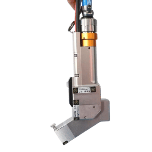
Different equipment options lead to differences in angle accuracy, repeatability, and cost. Each of the four tiers of the tool inventory possesses a specific accuracy envelope.
| Tier | Tool type | Angle accuracy | Edge width capacity | Indicative price | Mejor para |
|---|---|---|---|---|---|
| Nivel 1 | Manual / handheld grinder, chamfering knife | ±2°-3° | Up to ~6 mm | $200-$1,500 | Touch-ups, repair, very small lots |
| Nivel 2 | Pneumatic beveler | ±1°-2° | Up to ~15 mm | $1,000-$3,500 | Hazardous areas (no spark), confined spaces |
| Tier 3 | Portable electric milling beveler | ±1° | Up to ~21 mm | $2,000-$10,000 | Field work, on-site fabrication, mid-volume shops |
| Tier 4 | CNC industrial milling and beveling machine | ±0.5° | Up to ~35 mm (typical) | $10,000-$50,000+ | High-volume production, code-critical work, repeatable tolerances |
✔ Industrial CNC beveling
- ±0.5° repeatability across thousands of joints
- Multi-step compound bevels in one pass
- Operator skill removed from the tolerance equation
- Cycle time predictable for production planning
⚠ Industrial CNC limitations
- Capital cost; ROI requires sustained throughput
- Workpiece fixturing footprint required
- Not portable — field repairs still need handheld tools
- Programming time on small-batch orders
Breakeven for a shop choosing between a Tier 3 portable or a Tier 4 CNC: 3,000-5,000 joints/year of normal geometry. Under that, the portable electric milling beveler makes most code work; over that, the CNC pays for itself even with increased scrap. To browse other industrial beveling machine options:industrial beveling machine alternatives.
CTA decision: a quick way to scope a purchase is to take the most demanding code in the shop’s queue (usually AWS D1.1 CJP or API 1104), back-calculate the angle tolerance, and choose one tier above that. Picking the same tier as the tolerance leaves no margin for tool wear.
Compare Industrial Beveling Machines →
Material Compatibility: Steel, Stainless, Aluminum, Composites
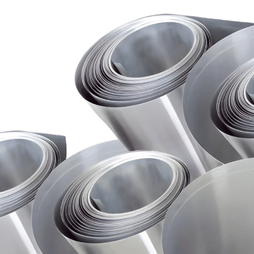
Material does not select the bevel geometry itself – the wall thickness and welding process turn here. Material specification chooses the cutting parameters (speed, feed, lubrication) and the surface-finish criteria of acceptance. ISO 9013:2017 divides the thermal cuts into ranges 1 through 5 of the perpendicularity tolerance, with the largest tolerance allowed increasing with material thickness – 5 mm has a different maximum dimension than 50 mm.
How can you bevel a perfect edge?
“Perfect” depends on the downstream welding process. In stainless tube, a GTAW root pass needs a clean contamination-free edge with a controlled root face (2 1/2 mm 0.5 mm); in carbon steel plate a SMAW fill pass can put up with a larger root opening and more surface roughness. Match the cut to the next process – no single perfect specification gives you a better weld and a lower cost.
| Material | Preferred bevel method | Watch for | Surface-finish standard |
|---|---|---|---|
| Carbon steel | Cold cutting, plasma, oxy-fuel for thick plate | Heat-affected zone on thermal cuts >25 mm | ISO 9013 Range 2-3 |
| Stainless steel | Cold cutting (no carbon contamination) | Avoid carbon-steel grinding wheels (cross-contamination) | ISO 9013 Range 1-2; 3-A Sanitary for hygienic |
| Aluminio | Cold milling beveler with carbide cutter | Oxide layer at the edge — clean before welding | AWS D1.2 (aluminum welding code) |
| PVC / thermoplastic pipe | Hand chamfer tool, plastic-pipe beveler | Avoid heat — friction melting deforms the edge | Per pipe manufacturer’s solvent-weld spec |
| Composites (FRP, CFRP) | Diamond-tipped router, water-jet | Fiber pull-out, delamination at the edge | Per panel manufacturer spec |
Hygienic stainless pipe for food and beverage and pharmaceuticals are covered by EHEDG and 3-A Sanitary Standards. Bevel surface finish has to be fine enough to keep bacterial ‘pockets’ from holding at the weld toe – orbital is the typical downstream process, so the bevel needs to feed it cleanly.
Why Beveling and Chamfering Matter (Industrial Use Cases)
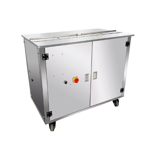
Edge preparation is structural insurance. All the really hard work happens before the arc is struck, and what you do on the plates determines if they meet code, or if in two weeks’ time you have a failed inspection. The case for accuracy is not as soft as most mill people suppose.
What is the purpose of chamfering?
Chamfering creates four very practical advantages: eliminating the sharp 90 that cuts fingers and tears gloves, providing a guiding surface so that fasteners tend to go in straight, eliminating stress concentrations at corners that would otherwise start fatigue cracks, and providing better appearance on exposed edges. In CNC, 0.5 45 is the ballpark default on through-hole screw holes – that is the assembly reason, not the aesthetic one.
Compared to chamfering, beveling benefits the welder, not the assembler. Its uses are to make sure the weld deposits go to the right places, sidewall fusion is complete and proper, and final root quality is achieved. When the wrong process substitutes the right one, the weld, though it will look OK in the end, may fail in service.
Type D Common Misconception: “Bevel Is Just for Looks”
For structural or pressure-welded work, beveling is the only thing that allows the welder to form the weld properly. An edge preparation – in the form of a technical report from Dtic on what makes a good edge – actually affects the life of a coating over a weld as well as quality of the actual weld it supports. A ‘pretty’ bevel might have failed the job years ago.
“Most shops think they understand AWS D1.1 beveling specifications. Then they fail an x-ray and go straight for the blame-shift to the welder. Fix it upstream, starting at the bevel itself.”
| Use case | Why edge prep matters | Typical industry |
|---|---|---|
| Weld preparation | Defines penetration depth and fusion quality | Shipbuilding, pressure vessels, oil & gas pipeline, structural steel |
| Assembly fit | Lead-in geometry guides parts into mating holes / sockets | Automotive, aerospace, fastener manufacturing |
| Safety burr removal | Removes sharp corners that cut hands, snag clothing, damage seals | All metal working; especially handheld products |
| Stress redistribution | Smooths transitions, reduces stress concentration at corners | Structural, automotive brake pads, gear edges |
| Sealing surface | Provides controlled bearing surface for gaskets and O-rings | Hydraulic systems, pharmaceutical / food piping (EHEDG, 3-A) |
Chamfering vs Deburring vs Filleting: Don’t Confuse the Processes
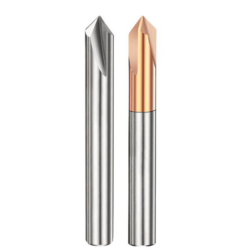
In shop talk, four edge-finishing processes are used interchangeably: chamfering, beveling, deburring, and filleting. Each of these processes does different things, and instead of being used as alternatives, they often run as a sequence.
| Proceso | Geometry produced | Primary purpose | Order in workflow |
|---|---|---|---|
| Bisel | Sloped edge, variable angle, often through-thickness | Weld joint preparation, structural fit | Pre-welding, defined by WPS |
| Chafre | Flat angled cut at corner, typically 45° | Assembly lead-in, edge safety | Post-machining, before deburring |
| Deburr | Elimina residuos metálicos sueltos, sin ángulo definido | Seguridad superficial, adherencia de pintura, protección contra sellos | Después del biselado, última operación antes del montaje |
| Filete (redondo) | Borde curvo, radio definido | Alivio del estrés, flujo de fluidos, sensación ergonómica | Diseñado en CAD; producido mediante herramientas o postmecanizado |
“Chamfering es lo mismo que desbarbar”. Esto no es cierto. El biselado crea un ángulo definido y tolerado, por ejemplo, 0,5 × 45°. El desbarbado, por otro lado, es el proceso de eliminar el metal residual, no uniforme e ilimitado que queda después del mecanizado y no deja una geometría definida. Si bien un chaflán puede desbarbar como efecto secundario, el trabajo impulsado por especificaciones considera las dos operaciones separadas porque están sujetas a inspecciones diferentes.
En un CNC más normal, un orden típico es: gubia-máquina, clave el chaflán, todos los bordes y los bordes restantes y luego inspeccione si hay esquinas afiladas usando ISO 13715 clase de tolerancia de borde. El filete sólo parece ser una característica de algunos sistemas CAD en el sentido de que se crea a partir de una herramienta de radio de esquina durante el mecanizado, no después.
Perspectivas de la industria 2025-2026: automatización CNC y evolución de estándares
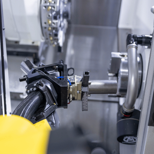
Es probable que la industria de preparación de bordes se vea influenciada por tres factores principales en los años 2025-2026: automatización de precisión, adopción de biseladores portátiles en el sitio y cambios en los estándares. Cada uno de ellos está respaldado por datos de tendencias de búsqueda. En los datos más recientes del volumen de búsqueda de Google en EE. UU. para la preparación de bordes, el plazo aumentó aproximadamente 5 veces entre junio y septiembre de 2025. Se observó un aumento similar en el volumen de búsqueda de achaflanado durante el mismo período, lo que indica que los equipos de adquisiciones están investigando posibles actualizaciones.
Tendencia 1: La automatización de precisión se convierte en el valor predeterminado de alto volumen
Las fresadoras y biseladoras CNC que tienen una precisión de ángulo de ±0,5° están pasando de los bienes de capital de alta gama a los estándares básicos para trabajos de código crítico. La razón es simple: considerando las bandas de tolerancia de ±5° para AWS D1.1 y ±2.5° para ASME B16.25, una máquina CNC solo usa 10-20% de la banda permitida, dejando mucho espacio para el desgaste de la herramienta. Por el contrario, las herramientas manuales y neumáticas con una precisión de ±2-3° se desgastan debido a que los cortadores se vuelven opacos y tienen tolerancia de salida rápidamente después del primer uso. Consumen 40-60% de la banda.
Tendencia 2: Se expande el biselado portátil en el sitio
Los biseladores de fresado eléctrico portátiles se están volviendo más populares en la reparación de campos de construcción naval, oleoductos y cambios de petróleo y gas. Impulsar esta tendencia es una precisión de ángulo mensurable. Si bien los biseladores pueden producir bordes con un grado de cumplimiento, los sopletes de oxicombustible seguidos de la molienda manual rara vez producirán bordes codificados. En la mayoría de las aplicaciones de trabajo de campo, se pueden utilizar biseladores eléctricos portátiles en lugar de biseladores neumáticos sin chispas, que todavía se requieren en ciertos entornos peligrosos.
Tendencia 3: Revisión de Normas (ISO 9013:2017 y AWS A2.4:2020)
ISO 9013 revisada en 2017, reemplazando la edición de 2002, con bandas de tolerancia de perpendicularidad más estrictas. Las referencias WPS obsoletas pueden estar usando estos números más antiguos de 2002. AWS A2.4:2020 (octava edición) introdujo reglas explicativas de uso para soldaduras con ranuras acampanadas que los detallistas previamente establecieron a su discreción. Espere resistencia del inspector si su tienda hace referencia a símbolos de soldadura anteriores a 2020.
Qué planificar en 2026
Para las compras de capital de alcance de las tiendas de 2026, el consejo conveniente es comprar con un nivel de precisión por encima de la llamada de código más estricta en la cola, es decir, un biselador eléctrico portátil en 1 como piso y CNC en 0,5 como techo. Las herramientas neumáticas y manuales permanecen solo para trabajos de nicho. Para los talleres que realizan trabajos mixtos AWS D1.1 / ASME B16.25, eso significa que un biselador portátil de corte en frío con precisión comprobada 1 es el punto de entrada, no la actualización.
Preguntas frecuentes
P: ¿Qué es un chaflán biselado?
Ver respuesta
P: ¿El biselado se llama biselado?
Ver respuesta
P: ¿Cuándo es necesario biselar versus biselar?
Ver respuesta
P: ¿Cuáles son los beneficios de biselar componentes?
Ver respuesta
P: ¿Por qué es tan importante el biselado de alta precisión?
Ver respuesta
Referencias y fuentes
- AWS D1.1/D1.1M Código de soldadura estructural « Acero « Sociedad Americana de Soldadura
- Código de tubería de proceso ASME B31.3 «Sociedad Americana de Ingenieros Mecánicos
- API 1104 Soldadura de Tuberías e Instalaciones Relacionadas « Instituto Americano del Petróleo
- ISO 9013:2017 Corte térmico « Clasificación de cortes térmicos « Organizare internațională pentru standardizare
- ISO 9692-1:2013 Soldadura y procesos afines « Tipos de preparación de juntas « Organizare internațională pentru standardizare
- AWS A2.4: Símbolos estándar de 2020 para soldadura fuerte y examen no destructivo « Sociedad Americana de Soldadura
- Reddy et al., “Un estudio sobre los efectos de la preparación de juntas y bordes para producir soldaduras sin distorsiones y con reducción de costos” « Seminario Nacional de Soldadura / IIT (documento de investigación)
- Informe DTIC ADA452427: El efecto de la preparación de bordes en la vida útil del revestimiento «Centro de Información Técnica de Defensa de EE. UU
- Conocimiento laboral de TWI: costos de soldadura (continuación) « El Instituto de Soldadura
- Grupo Europeo de Ingeniería y Diseño Higiénico (EHEDG) «asociación de ingeniería higiénica
- 3-A Normas sanitarias, Inc. «organizare de standarde sanitare
- ISO 13715:2017 Bordes de forma indefinida « Indicación y dimensionamiento « Organizare internațională pentru standardizare
Acerca de este análisis de preparación de bordes industriales
Esta guía sintetiza los requisitos de AWS, ASME, API e ISO con un estudio ResearchGate de 2014 sobre economía de metales de soldadura y rangos de precisión de equipos probados en campo de fabricantes de máquinas biseladoras industriales. La matriz de 8 juntas de la sección 3 se compiló a partir de referencias cruzadas de AWS A2.4:2020, ISO 9692-1:2013 y la guía publicada sobre el espesor de las paredes «no se extrae de ninguna fuente competidora. Los niveles de precios de la Sección 5 reflejan los precios de lista de 2025-2026 para equipos de fresado y biselado en los mercados OEM de EE. UU. y China.
Revisado por el equipo de ingeniería de RESIZE « RESIZE fabrica fresadoras y biseladoras, posicionadores de soldadura, rotadores, manipuladores, mandriles, cortadoras de plasma y líneas de producción de torres eólicas. La revisión de ingeniería se basa en datos de puesta en servicio en el piso de fábrica en líneas de productos de vidrio, tuberías y biseladoras portátiles (profundidad de corte de 0 a 25 mm, ángulos de 15° a 75°, potencia de 2,8 kW, 2000 a 6000 RPM).
Artículos relacionados
- ¿qué es una máquina biseladora « fundamentele echipamentei
- ¿cuál es el estándar para biselar « referințe de cod în profund
- Elegir la máquina biseladora de tubos adecuada « selección de equipos por tamaño de tubería
- Fresadora y Biseladora « Pilar « gama completa de equipamiento y especificaciones