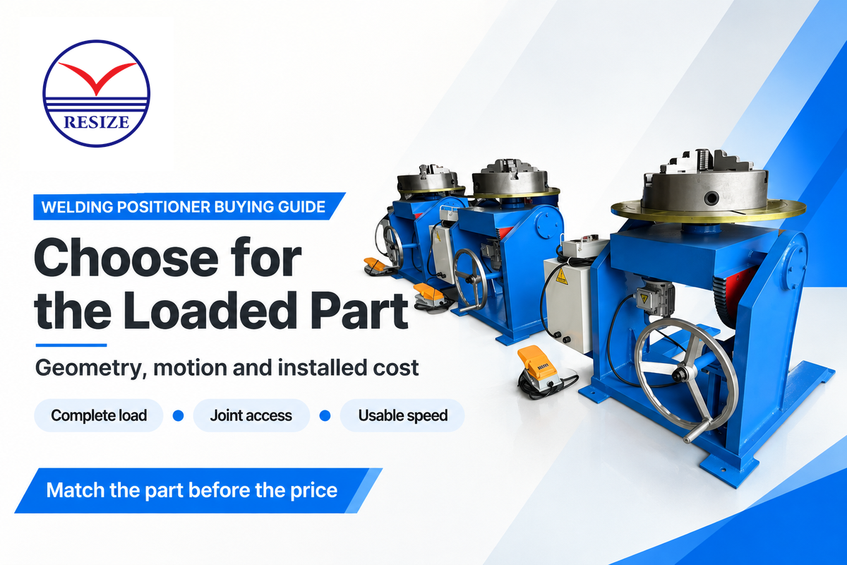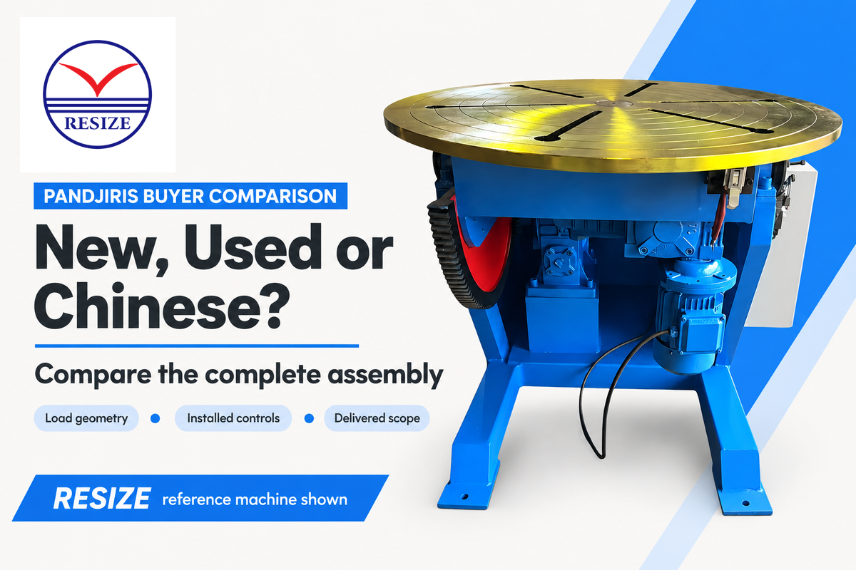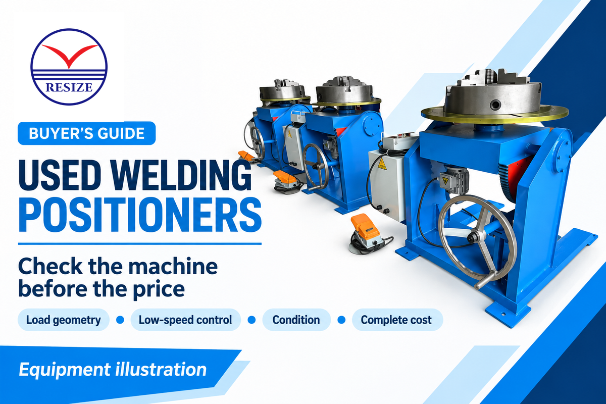
To choose welding positioner equipment, first consider the loaded workpiece: its mass and center of gravity; access for welding and swept clearance; and required rotation speed. Then select the support layout that meets those requirements and evaluate fixtures, controls, and installed cost. A machine to support the part also has to present all the required joints to the welder.
A small flange and an irregular frame may demand different machines, even if their weights are the same. This basic buying guide connects part geometry to a usable purchase specification for manual welding and automated welding. The welding procedure still defines the allowable process settings and positions.
- Identify the limiting part families and required joints.
- Select a support layout and check the loaded motion.
- Compare complete quotations using a representative-part trial.
Start with the weld, the workpiece and the production mix
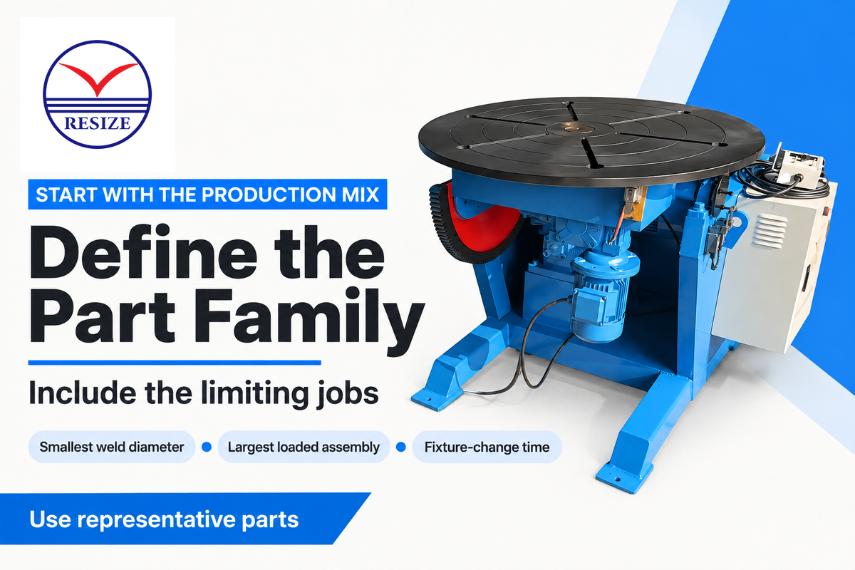
Select welding equipment for representative part families that include the smallest weld diameter and the largest loaded assembly. Note joint orientation, fixture weight, setup time and handling method for each family. This determines if a single positioner can cover the work or if a second positioner reduces an excessive number of changeovers and awkward loading.
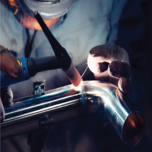
Welding positioners are mechanical devices used to hold and move work. The welding machine provides process energy. Weld positioners hold and rotate workpieces; the table must fit the specific welding task. Purchasing a powered table solves only a part of the welding operation: fit-up, torch access, welding procedure and inspection remain separate production activities.
Imagine a shop alternating small flanges with branch-heavy pipe assemblies. The small flanges may be able to be supported on a rotary positioner table, but the branch-heavy pipe assemblies may need support beyond the table. As the pipe assembly turns, the branches sweep by the column. Moving everything to a larger machine could solve the support problem while increasing fixture changes for the small parts. Separate the two families on the quotation form. Determine how long it takes to load, clamp, weld, reposition, and unload, then determine the batch quantity between fixture changes. A comparison based only on arc-on time would be misleading because the operator and crane would still have a lot of work to do.
Le NIST publication on flexible lines with setups analyzes the impacts of setup and product-mix variations on a furniture production model. Its useful buying principle is to consider variations separately; the results aren’t welding productivity figures. Consider the parts already on your schedule, then add confirmed future welding projects that would change the required envelope. The extra movements on advanced positioners earn their cost when those movements address a recurring access problem or a repeated setup.
Choose the positioner type: tilt-turn, tailstock or turning rolls
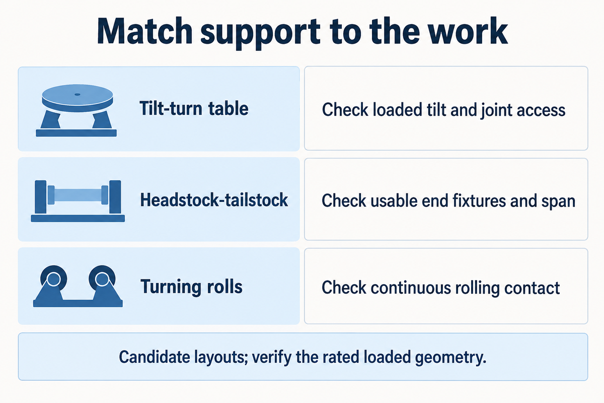
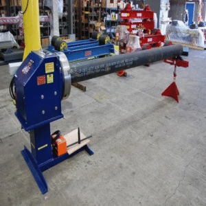
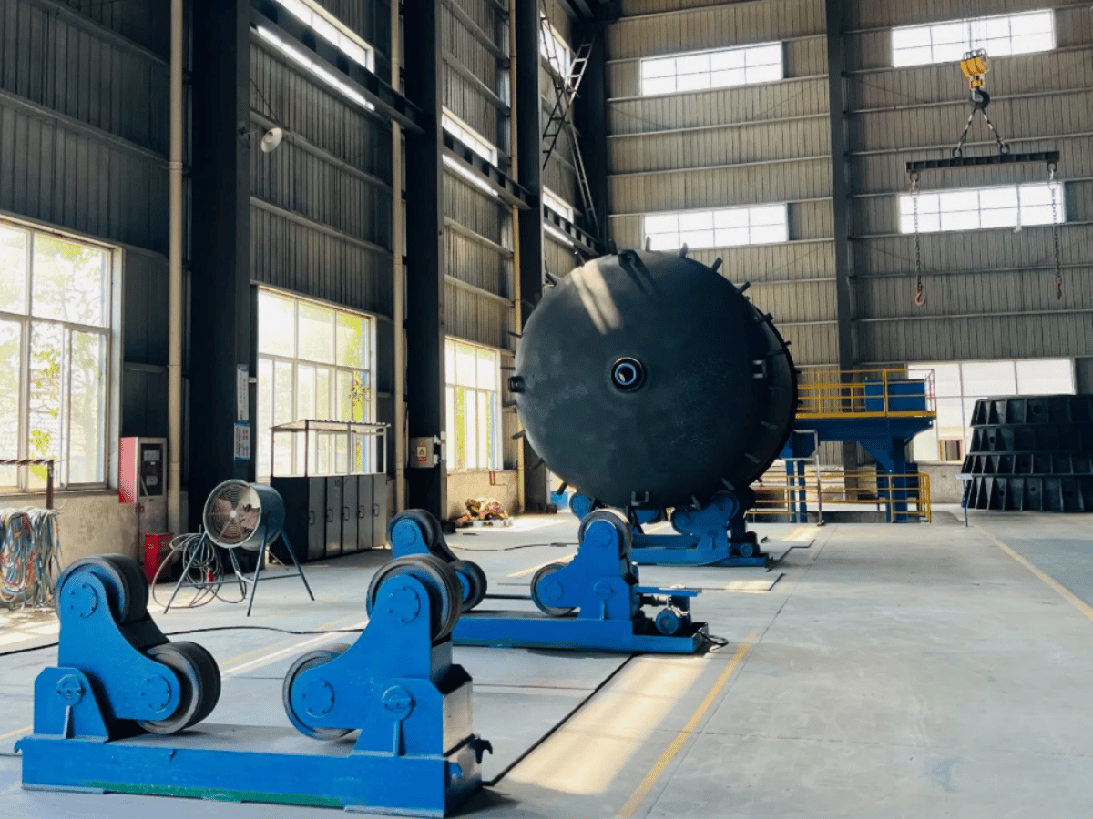
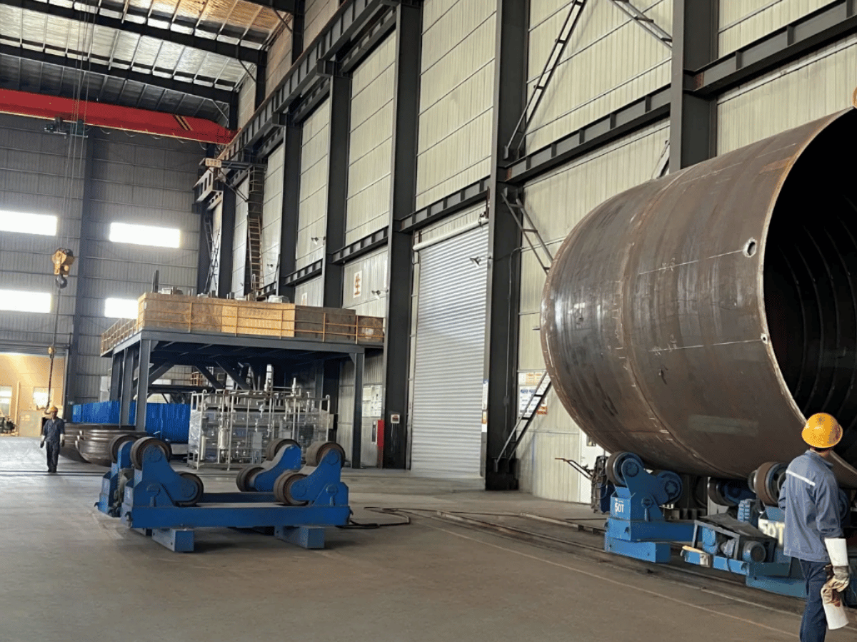
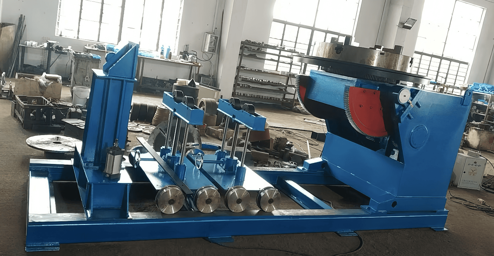
Tilt-turn weld positioners may work for a process that requires rotating the table and changing the welding angle. Headstock-tailstock systems support assemblies between end fixtures. Rolls rotate cylindrical work on the outside of the part. Depending on the available support points and access to joints, choose among these layouts and check if the complete loaded geometry fits the proposed machine.
Quels sont les différents types de positionneurs de soudage ?
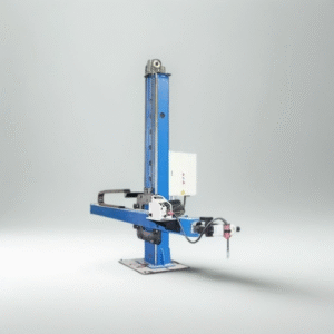
The main types consist of rotary welding positioners, tilt turn tables, head-and-tailstock positioners, and other machines with additional lifting and/or coordinated axes. Turning rolls are a related option for cylindrical vessels and pipes. The different types of positioners support and move the workpiece in distinct ways, so names alone are a poor basis for comparing quotations.
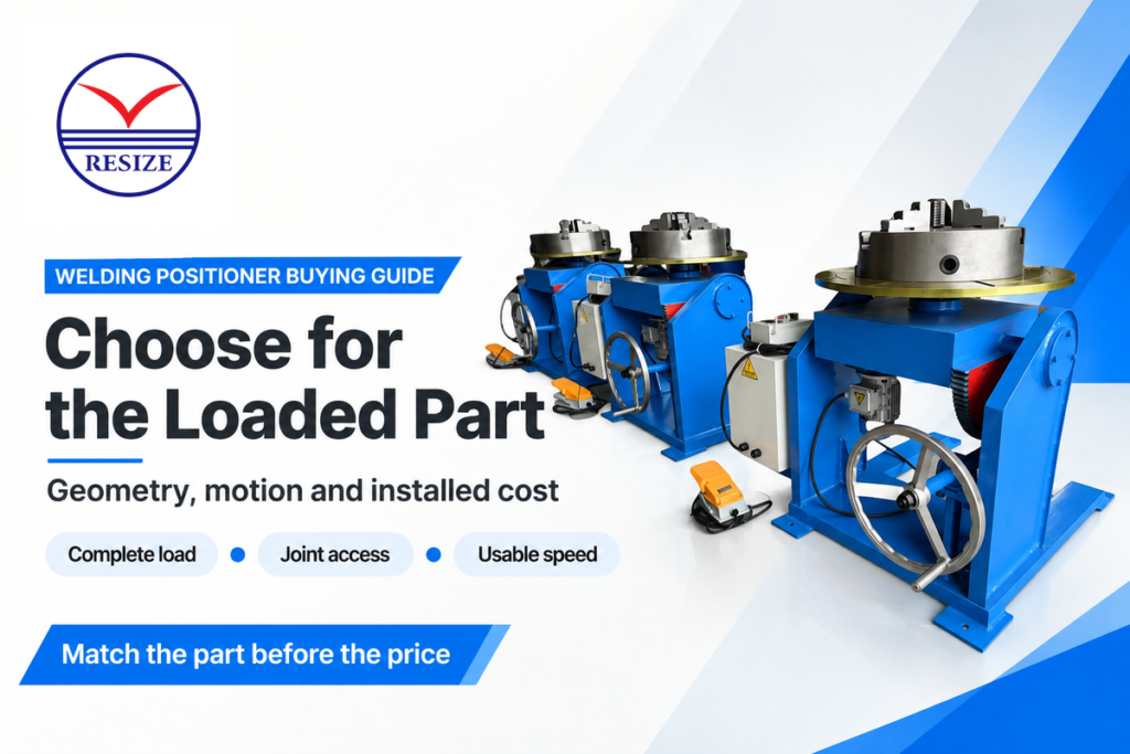
Welding positioners come in various motion layouts, including rotary positioners with a fixed table angle. A manual welding positioner may have hand-adjusted tilt with powered rotation, while another machine powers both movements. Positioners are designed for stated loads and movements. Ask whether the model can tilt the workpiece under load, and what mechanisms lock or control the axes. Every degree of freedom changes the swept space and fixture demands. Welders gain greater flexibility only when those movements provide access to joints they actually need to reach.
| Workpiece or task | Candidate positioner type | What decides the choice |
|---|---|---|
| Compact circular flange | Rotary table | Concentric chucking and required speed at the weld diameter |
| Flange requiring an inclined weld | Tilt-turn table | Loaded tilt range and access around the joint |
| Short pipe spool | Table with suitable chuck and support | Overhang, through-bore needs and branch clearance |
| Long pipe assembly | End-supported system or turning rolls | Available end fixtures versus a continuous rolling surface |
| Cylindrical tank shell | Rouleaux tournants | Shell support, surface contact and circumferential travel |
| Irregular structural frame | Headstock-tailstock or rated tilt-turn fixture | Support span, offset load and access to all joints |
| Assembly with protruding branches | Raised or end-supported layout | Full rotation sweep including fittings and clamps |
| Part with blocked end faces | Table fixture or suitable rolling support | Where the fixture can locate the part without covering welds |
| Repeated robot-welded assembly | Robot-compatible indexed or coordinated axes | Control integration and whether motion continues during welding |
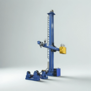
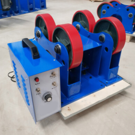
For a long assembly, compare headstock and tailstock configurations with the support options used for pipe welding positioners. Turning rolls require a suitable surface on which to roll the workpiece. An uneven surface, like a branch or irregular shell, can obstruct that. An end-supported solution requires usable fixture interfaces at both ends, and sufficient rated support span to take the load of the assembly. If the weld requires loaded tilt, reject any proposed layout that cannot provide that movement within its load rating; simple rotation alone will not reach the required orientation.
Check total load, center of gravity and rated moments
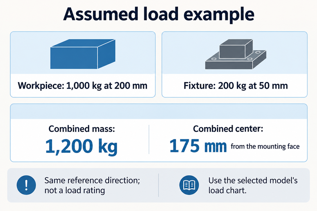
Rate the combined weight of workpiece and fixture, including the chuck, clamps and other components added during assembly. The moments which the rotation and tilt drives resist are determined by the position of the center of gravity. A nominal payload figure holds true only when the load condition is as stated; for the case at hand, use the selected model’s load chart for the proposed geometry.
It takes more effort to hold a weight farther from your body. A positioner has the same problem; offset load creates a moment. The moment of rotation uses the perpendicular offset of the center of gravity of the combined load from the axis of rotation. Tilt moment depends upon the distance from the tilt axis, and includes the machine’s inherent overhang, where the manufacturer has specified it.
As a simple assumed comparison, a 1,000 kg workpiece on a 200 kg fixture creates a 1,200 kg combined load. Treating only the part as payload omits 200 kg before any center-of-gravity calculation starts. For the same assumed setup, place the part center 200 mm from the mounting face and the fixture center 50 mm from it, measured along the same perpendicular direction. The combined center lies at (1,000 kg × 200 mm + 200 kg × 50 mm) ÷ 1,200 kg = 175 mm from that face. Adding a taller fixture also moves the combined center of gravity. Even if the combined mass stays below a brochure rating, that change can exceed the machine’s permitted moment.
Complete a loaded assembly drawing showing the mass and center-of-gravity location relative to the mounting face and rotation axis. Show various assembly states and the final part. Moving a clamp or adding a branch can change the controlling position.
When making a purchase decision for heavy-duty work, you must work within the manufacturer’s load limit and allowables. A guessed 25% margin can’t replace a model-specific chart. If an offset falls outside the allowable limit, change the fixture arrangement, or select a piece of equipment that is rated for that load case.
Verify swing clearance and the welder’s access
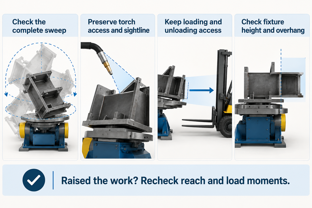
Check the swept envelope of the loaded fixture through every required rotation and tilt angle. Consider torch hardware, clamps, protruding fittings and cable and hose routes. Table diameter shows the mounting surface; it doesn’t create clearance between the assembly and the base, floor, columns and surrounding welding equipment.
We assume that the rectangular frame fits flat on the mounting plate. Consider a situation where during rotation, a corner moves farther from the axis than the center of an edge. Tilting the table can then bring that corner to the floor/base. Raising the work may restore clearance but put the upper joint beyond comfortable reach. A taller fixture can create another problem by increasing overhang. The buyer needs a drawing showing the complete movement, with the torch and the operator position, to decide on a higher base or different support layout. After that change, check clearance and load moments.
Don Burgart of Koike Aronson’s positioneering guidance in The Fabricator connects swing clearance with center of gravity and access. For complex geometries, show the supplier the corners and branches that move closest to fixed objects. A diameter-only sketch misses those features.
Usable welding angles mean the design must allow room for the torch, shielding-gas delivery and the operator’s line of sight to the joint. If the shop aims to minimize welders’ fatigue, assess reach and height of the working position during the trial, rather than assume that power motion eliminates awkward posture. Maintain access for loading and unloading during the trial, including when assessing ways of reducing welders’ fatigue. A machine can clear during welding, but it can obstruct the crane hook and force the operator to reach across the fixture to release it.
Match rotation speed to the weld path
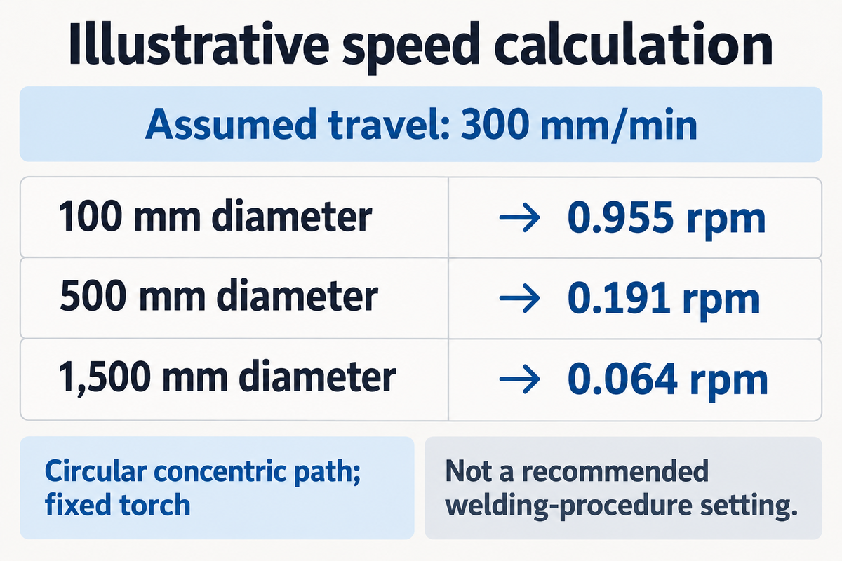
At an assumed travel speed of 300 mm/min, a 1,500 mm circular weld diameter needs approximately 0.064 rpm. A smaller weld diameter requires a faster rotation speed for the same surface travel. Calculate the extremes across the part family, then compare that interval with the machine’s permitted loaded speed range and smoothness.
When one rotary axis drives a circular, concentric weld path with a fixed torch, rpm = travel speed in mm/min ÷ (π × weld diameter in mm). If travel speed is given in mm/s, multiply it by 60 first. Use the weld path diameter, which can be different from the table or chuck diameter.
Consider an illustrative family with 100 mm, 500 mm and 1,500 mm weld diameters. Assume that 300 mm/min has already been selected for this geometry exercise; it isn’t a recommended welding-procedure setting. The 500 mm circumference is π × 500 mm, or about 1,571 mm, so the required rotation is 300 ÷ 1,571 = 0.191 rpm. Repeating the calculation for the other diameters gives the interval in the table. The smallest part determines the faster end; the largest determines the slower end. A candidate machine must run smoothly across that interval with the intended load and fixture.
| Weld diameter | Circumference, rounded | Required rotation, rounded |
|---|---|---|
| 100 mm | 314 mm | 0.955 rpm |
| 500 mm | 1,571 mm | 0.191 rpm |
| 1,500 mm | 4,712 mm | 0.064 rpm |
Assess the maximum speed of the adjustable speed controls and their adjustment at the operating speed. During a representative trial, observe starts, stops, and low-speed rotation of the loaded fixture. Jerky movements may cause travel to be uneven, though the average rpm may look correct on the display. Compare positioner speed controls against those requirements.
The type of welding doesn’t determine rpm by itself, and different welding conditions can define different travel speeds for the same part diameter. Other processes, such as Stick welding and flux-cored welding, use different travel conditions. A multi-process welding method requires a trial to evaluate each torch and access conditions. For noncircular paths, a moving torch or a coordinated welding robot-positioner system, calculate the combined trajectory and axis limits instead of applying a single circumference conversion.
Match fixtures and controls to quality control needs
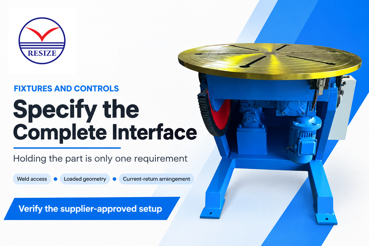
Fixtures must locate and hold the workpiece while leaving the joint accessible throughout the welding process. Match the control system to the required start, stop, speed, and indexing behavior. Include the welding-current return arrangement in the equipment scope because mechanical positioning and electrical compatibility are separate requirements of the installed station.
How do you match the chuck and fixture to the workpiece?
Check access to the weld, then match the chuck to the gripping surface, required bore, and combined loaded geometry. A fixture should hold the workpiece securely without covering the joint and without using an unsuitable contact surface. Include its mass and offset in the machine’s capacity assessment before comparing chuck diameter or jaw travel.
Long parts can require additional support even if their mass is low. Repeated jobs require a repeatable locating method. Clamping a part tightly doesn’t establish its weld position. For pipes that pass through the fixture, specify the usable through-bore and don’t assume that the chuck has one. Compare the welding positioner chucks against that completed part-family sheet.
For fixtures regularly used as part of the welding-current return circuit, OSHA 1910.254(c)(2)(iv) addresses the use of bonded joints or adequate current collectors. Protective grounding of the machine frame is a different issue. Specify the intended welding current and duty requirements with the supplier’s approved return arrangement; do not improvise a path through bearings or unrelated lifting equipment.
A foot pedal may provide start/stop control, variable speed, or both. Define the required behavior. Programmable controls may store positions or sequences, while a robot-integrated axis may require continuous synchronization with the torch. CNC labeling alone does not describe that interface. With a welding robot integrated into the station, determine which controller owns the positioner axes, and how motion is synchronized.
Quality control should assess fit-up and weld quality in accordance with the applicable procedure. A consistent weld requires a repeatable joint position as well as appropriate process settings. Precise positioning aids in presenting the joint in a consistent state, while better welds also require appropriate preparation and process control. Better results from a positioner trial should be judged against the same inspection criteria used in production. When adjusting the position, confirm that cables and hoses remain clear throughout the complete motion and not just at the starting position.
Compare installed cost and choose a supplier for your part mix
Match loaded geometry, speed range and support layout, then compare quotations. Ensure the purchase scope includes tooling, freight, installation, electrical work, commissioning, training and maintenance. A lower bare-machine price can lose its advantage when the shop must supply missing equipment or spend longer changing fixtures between production batches.
There is no useful universal installed-price range without matching the part, tooling and installation scope. Obtain like-for-like quotations for the same acceptance parts and included service.
“Sometimes one purchase can lead to several others.”
Modern welding positioners can offer stored programs and/or additional axes, but the value will depend on actual welding tasks. NIST’s purchasing guidance includes utilities, training, maintenance and end-of-life planning. Give the supplier the particular welding operation and the required acceptance level, and only then compare the offered features.
What is the best welding positioner?
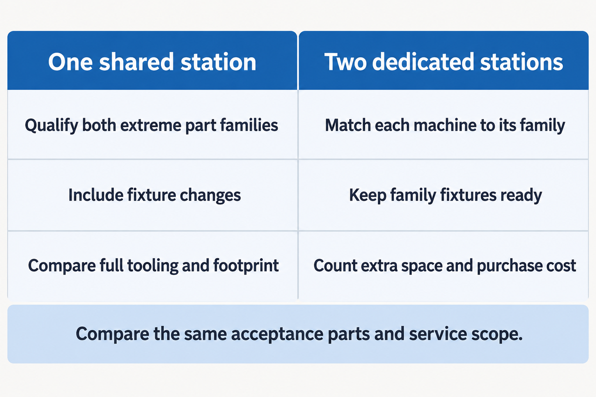
The best welding positioner is the least costly installed arrangement that meets the shop’s loaded geometry, motion and production requirements. For mixed applications in welding, compare the smallest circular part and the largest irregular assembly separately. Choose one system only when it handles both without unacceptable fixture changes or handling delays; otherwise compare two dedicated stations.
An optimal welding setup for a large frame may still be inconvenient for a small flange. Use the batch schedule and measured setup time to compare the two.
- Qualify both extreme part families on the same machine.
- Include fixture changes in the production schedule.
- Compare its installed footprint and complete tooling cost.
- Match each machine to its assigned part family.
- Leave family-specific fixtures ready between batches.
- Include the additional floor space and purchase cost.
A comparison of offers becomes useful only when all offers relate to the same part and same service.
| Constraint | Input to compare | Purchase consequence |
|---|---|---|
| Combined load | Part, chuck, fixture and clamps | Reject a rating based on the bare part alone |
| Rotation moment | Loaded center-of-gravity offset from rotation axis | Change the fixture or drive rating if outside the permitted envelope |
| Tilt moment | Loaded center of gravity relative to tilt axis | Assess fixture height before selecting the tilt drive |
| Full sweep | Corners, branches, clamps and cables in motion | Change support layout when the assembly strikes fixed objects |
| Smallest weld diameter | Procedure travel speed and required rpm | A slow maximum rpm can exclude the small-part family |
| Largest weld diameter | Required low-speed travel under load | Demand usable low-speed control, not only a nominal range |
| Gripping and bore | Contact surfaces, support span and through-bore | Include the correct chuck and auxiliary support |
| Batch changeover | Fixture-change minutes and batch frequency | Compare a second station when changeovers consume the benefit |
| Installation and service | Utilities, lifting, commissioning and spare parts | Compare complete installed scope and downtime arrangements |
For a hypothetical labor calculation, assume using welding positioners saves 8 labor minutes per part across 20 parts per day and 220 working days. Released labor time is 8 × 20 × 220 ÷ 60 = 586.7 person-hours per year. The inputs are assumptions, not measured RESIZE results. Released hours become useful capacity only when work is available and the next process can accept it; cash savings require a separate staffing or overtime change.
Send these inputs with the quotation request
- Representative part drawings, loaded mass and center-of-gravity locations
- Required welding angles, weld diameters and procedure travel speeds
- Fixture, chuck, through-bore and support requirements
- Batch quantities, fixture-change frequency and loading method
- Power supply, control interfaces, commissioning scope and acceptance parts
Compare the RESIZE welding positioner range with the part-family sheet completed thus far. Explore welding positioners with the smallest and largest assemblies on the same part-family sheet, so the quotation addresses the limiting jobs and their tooling.
Industry Outlook: Confirm Integration, Installation and Service
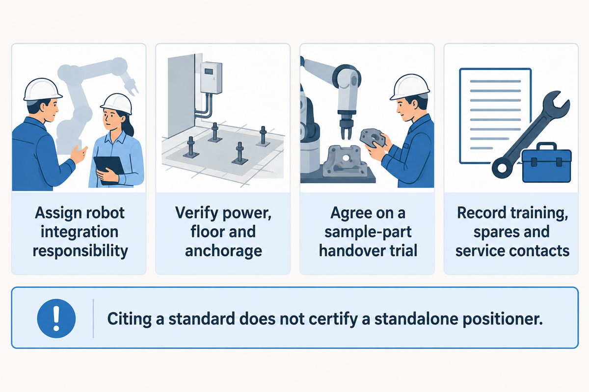
The 2025 revision of ISO 10218 makes robot-cell integration a specific purchasing discussion for projects that include industrial robots. Buyers should define who integrates the positioner, robot and supporting equipment, and who accepts the completed cell. A standalone powered table and a coordinated robot axis require different control and commissioning arrangements.
The official ISO 10218-2:2025 catalog records publication in February 2025 and covers industrial robot applications and robot cells. The Association for Advancing Automation’s revision FAQ explains the replacement of the 2011 editions. The standard addresses robot applications and cells; citing its number, however, does not certify each standalone positioner nor does it clarify which requirements govern a particular US installation.
In the case of the planned robot project, does the positioner index between welds or does it move continuously with the robot? With coordinated motion, interfaces and the level of programming and commissioning responsibility change. A table purchased now for manual welding might need different hardware for that task in the future. An advanced welding method also changes the integration brief if it requires a moving torch or additional process equipment. Put the planned conversion in the proposal; don’t assume “automation ready” is the complete technical explanation.
Installation remains a shop-level task for both manual and robotic systems. Verify power, floor and anchorage requirements with the responsible designer. OSHA 1910.212 addresses machinery guarding and anchoring fixed equipment. Provide access to the moving assembly, the loading route and the operator’s control position in the layout.
Both fume extraction and hot-work protection need to work with the intended movement. OSHA 1910.252 covers fire prevention and ventilation, including local exhaust hood performance at its remote distance from the weld. For covered servicing and maintenance, OSHA 1910.147 also addresses hazardous stored energy after isolation. Ask how the loaded assembly is restrained during the relevant maintenance activity.
Agree on a handover trial using sample parts (including loading, fixture changes, motion, and weld inspection) and record the training as part of delivery. The same applies to the service interval, spare part identification and service contacts. Training should cover the welding topics that affect daily setup, including fixture changes and approved current-return arrangements. Maintenance staff need the information to restore the station after a fault; production staff need a repeatable setup for the next batch.
Foire aux questions
Can welding positioners improve productivity?
Welding positioners can reduce repositioning time when handling and setup fit the production cycle.
Measure loading, clamping, welding, repositioning and unloading on representative workpieces. Better access can make welding easier, while the full cycle determines the production benefit. The useful gain depends on which step limits output and how often fixtures change. A shorter weld cycle brings little extra shop capacity when parts wait for the crane or inspection. Compare labor-minutes separately from elapsed minutes, especially when several people help turn a part, and use measured results for any payback calculation.
How do multi-axis welding positioners differ from traditional positioners?
Multi-axis systems add controlled movements beyond basic rotation.
Tilt or lifting axes can expose additional joints and change the working height. Each movement also changes the loaded envelope, fixture demands and control requirements. Select the movements needed for your joints rather than the largest axis count. For robot work, distinguish independent positioning between welds from synchronized travel during a weld; the latter needs a compatible robot control and an integrated motion plan.
Quel est le rôle des positionneurs de soudage dans les systèmes de soudage automatisés ?
A positioner presents the joint to the torch and can move it during welding.
Simple systems index the part and hold it while the torch completes a weld. Coordinated systems move the loaded part with the robot along a planned path. The chosen arrangement affects interfaces, programming and cell commissioning. An automatic welding machine still needs suitable fit-up and a qualified process, so evaluate the complete welding task rather than assuming that powered rotation alone will automate it.
Which welding position is considered to be the easiest?
Flat or downhand welding generally offers easier access and puddle control.
The qualified procedure and joint requirements determine the permitted welding position. Position the work within those limits.
What are the common usage issues with welding positioners?
Selection problems often involve clearance, fixture load, gripping or unsuitable rotation control.
Check the complete loaded setup against the machine manual. An underestimated fixture mass, blocked weld access or unsuitable current-return arrangement can make an otherwise useful machine difficult to operate. Stop when the assembly is unsecured or equipment behaves unexpectedly, and involve the responsible maintenance or engineering team. Adding a guessed counterweight or changing a stated load limit isn’t a general repair.
Is a welding fixture the same as a welding positioner?
A fixture locates and secures the workpiece; a positioner moves the loaded assembly.
Their combined mass, geometry and mounting connections must suit the selected machine.
References & Sources
- NIST: Flexible Lines with Setups: Analysis, Improvement, and Application (2016).
- NIST MEP: A Manufacturer’s Pre-Purchase Guide to Equipment (2020).
- The Fabricator: Welcome to the World of Positioneering, Don Burgart (2015).
- ISO 10218-2:2025: Industrial Robot Applications and Robot Cells, public catalog scope.
- Association for Advancing Automation: Updated ISO 10218 FAQ (2025).
- OSHA 29 CFR 1910.254: Arc Welding and Cutting.
- OSHA 29 CFR 1910.212: General Requirements for All Machines.
- OSHA 29 CFR 1910.252: General Welding Requirements.
- OSHA 29 CFR 1910.147: Control of Hazardous Energy.