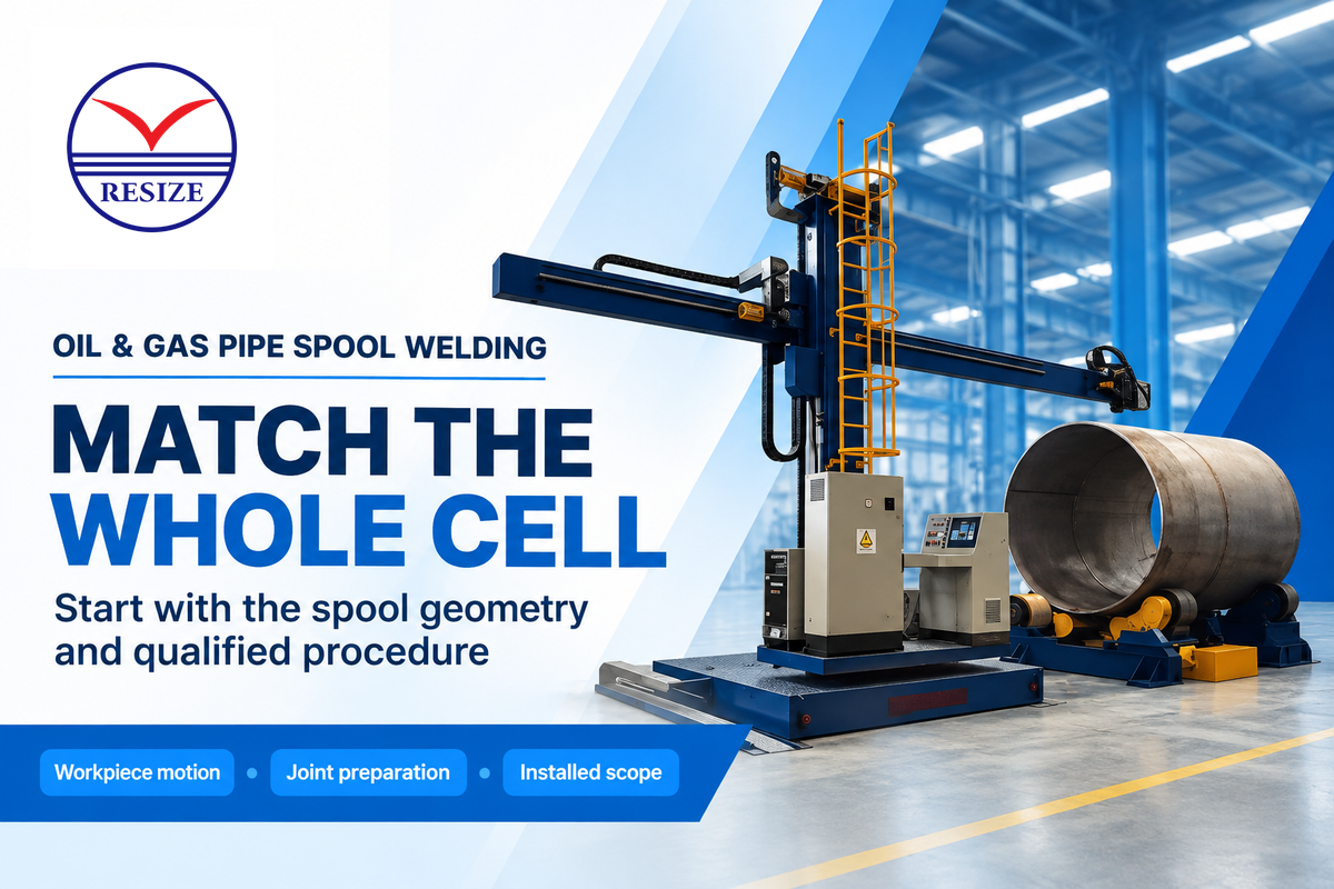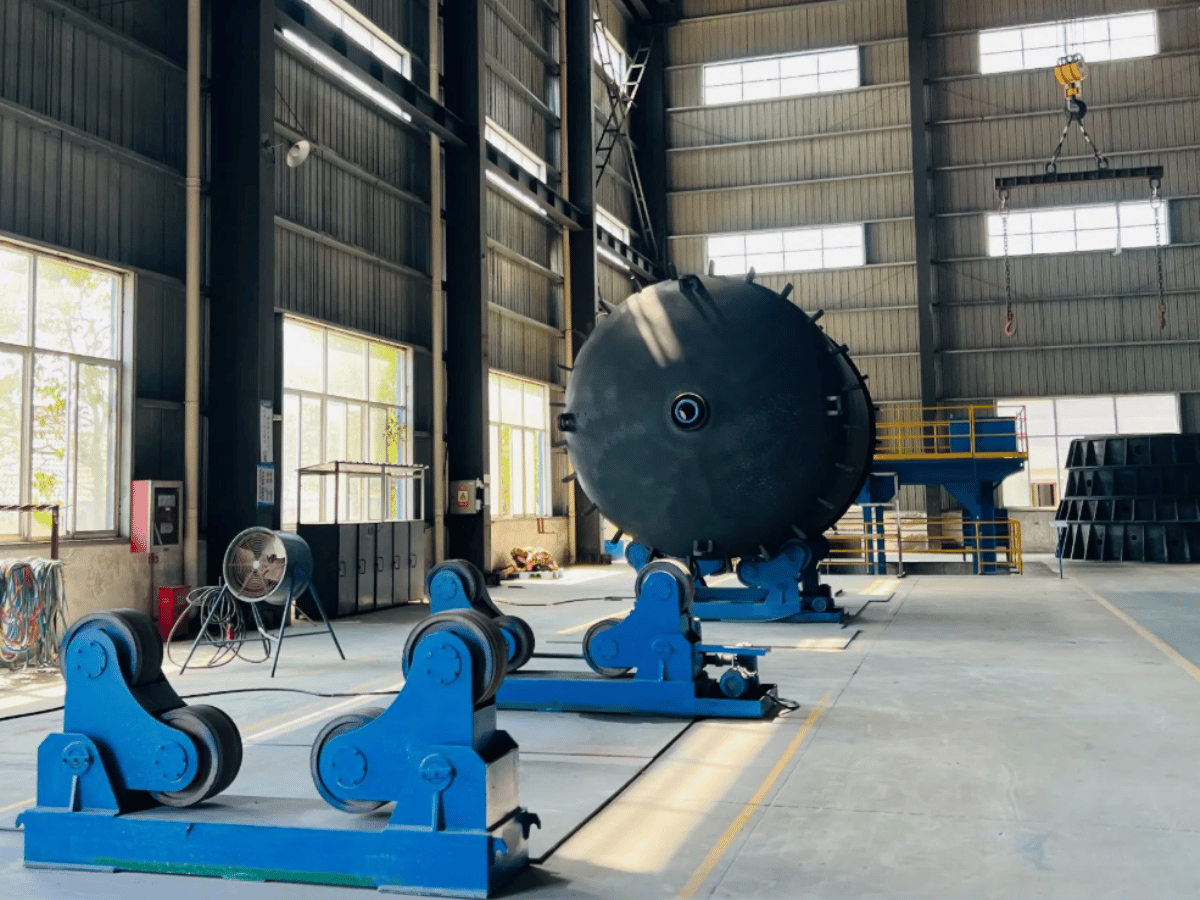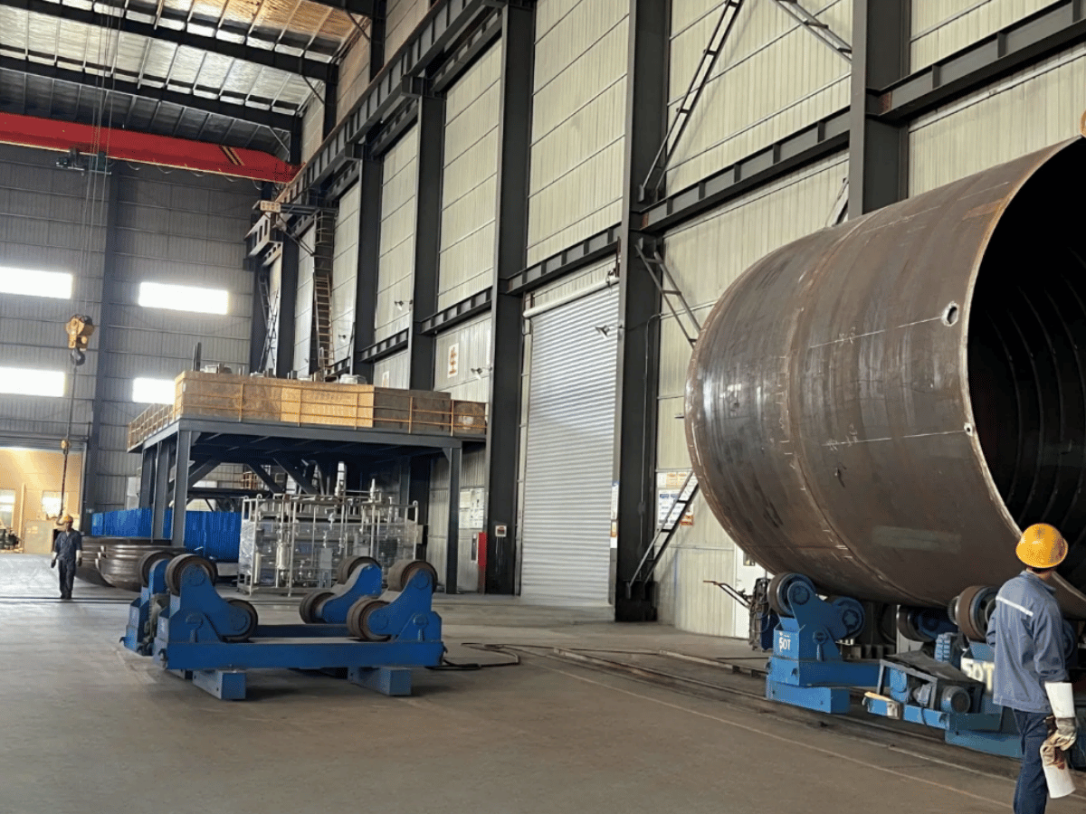
Welding equipment for oil and gas pipe should suit how the entire spool moves, how each joint is prepared, and how the shop releases completed work. For pipe that’s supported, cylindrical, and able to turn, use a rotator. When pipe is clamped, use a positioner. Use an orbital system when pipe is fixed.
A larger power source can’t clear an elbow that hits the floor. A faster torch can’t increase the supply of prepared joints. This guide links the equipment package to the production constraints and shows how to compare the installed cost and cash savings. The focus is on shop fabrication of pipe spools; pipelines (line work) have their own projects and regulation.
By GW · Updated November 2026
Pipe Welding Equipment: What a Spool Shop Needs
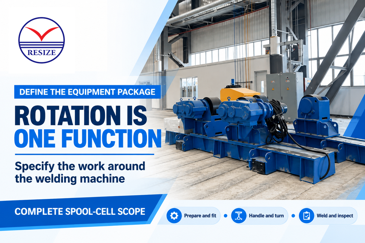
A pipe spool welding cell needs preparation and fit-up tools, controlled workpiece or torch motion, a compatible welding package, and arrangements for safe handling and inspection. Buy these as a connected process. The required machine changes when the assembly must remain fixed, when its center of gravity shifts, or when a different joint needs access.
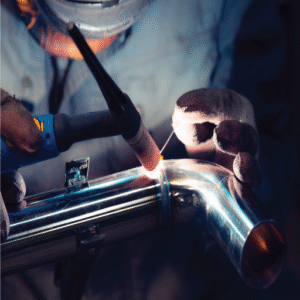
Industrial welding projects start with the welding specification. TWI specifies argon shielding and backing gas with a minimum purity of 99.9995% for industrial orbital welding with 316L stainless steel tubing. Tungsten inert gas welding (also known as TIG or Gas Tungsten Arc welding) uses a different torch and control package from wire-fed welding. The chosen power supply, feeder, shielding gas, consumables and cooling system must support the qualified welding procedure. A manipulator moves or supports the welding head; it doesn’t perform all these functions by itself.
| Function | Equipment to specify | Buying question |
|---|---|---|
| Cut and prepare | Saw, beveling machine and cleaning tools | Can the actual material and wall be prepared consistently? |
| Fit and tack | Alignment fixtures, clamps and supports | Can the joint geometry be repeated across the order mix? |
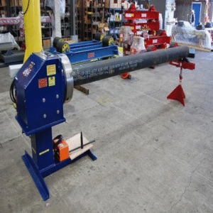
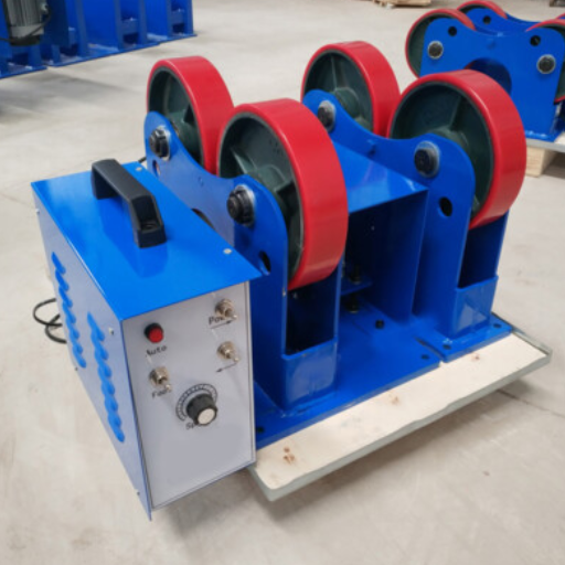
| Turn a cylinder | Driven and idler welding rotators | Are support contact, traction and full rotation suitable? |
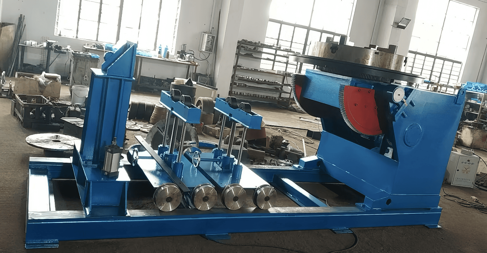
| Orient an assembly | Clamped sudare poziționer | Does the complete load fit its torque and center-of-gravity envelope? |
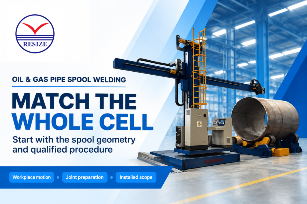
| Carry the torch | Column-and-boom welding manipulator | Is the required loaded reach and working motion included? |
| Weld fixed pipe | Orbital power/control package and suitable head | Can the head clamp, travel and withdraw at every joint? |
| Make the weld | Power source, torch, wire feed and gas supply | Does the complete package support the procedure? |
| Handle the work | Lifting equipment, transfer supports and rated fixtures | How does a finished spool leave without blocking the next one? |
| Control and release | Exposure controls, inspection equipment and records | Which checks occur at the cell and which occur downstream? |
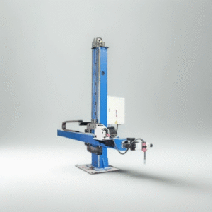
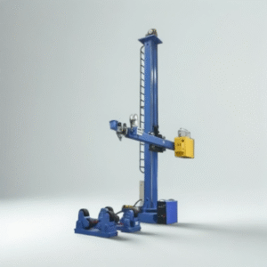
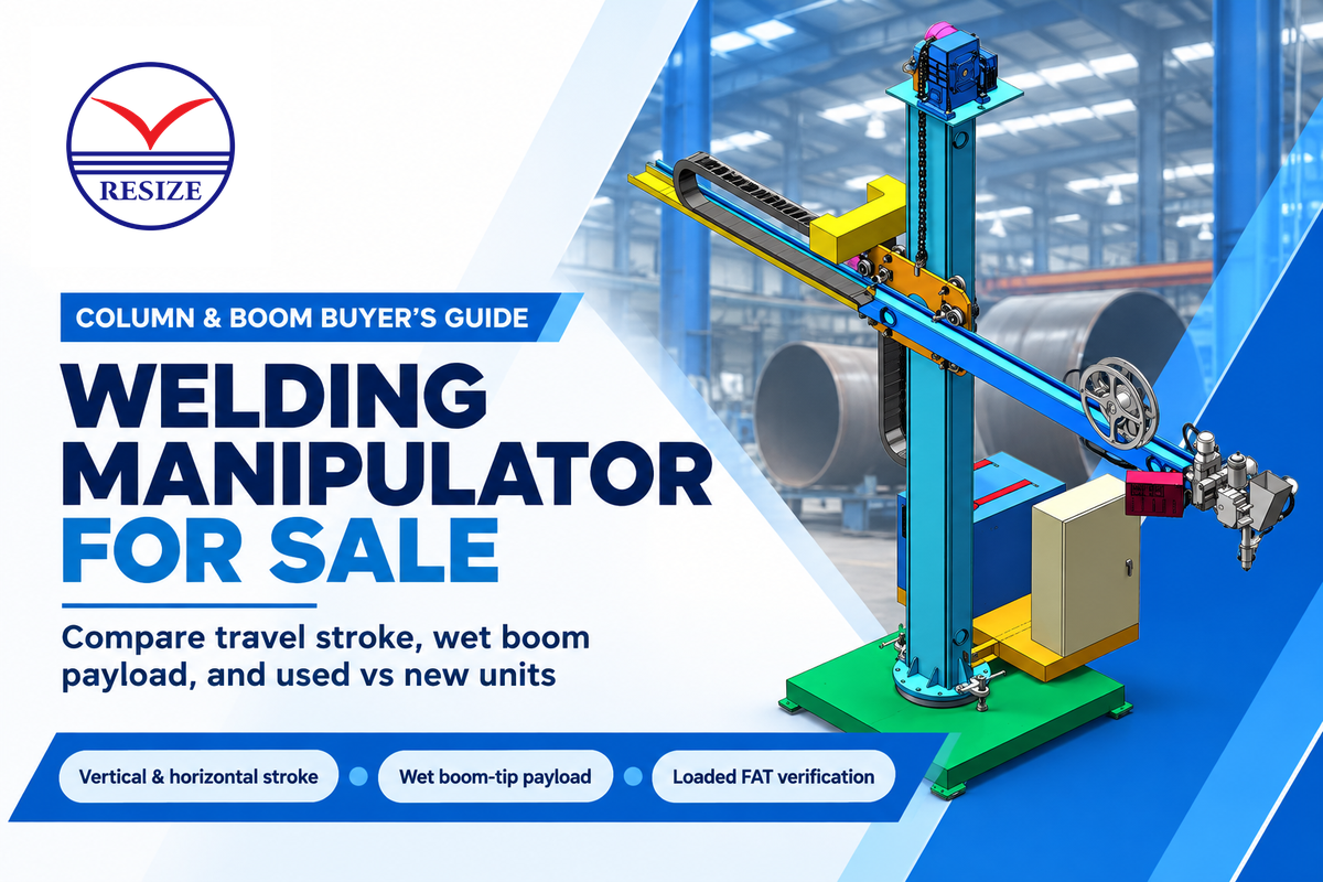
Long assemblies may require a column-and-boom welding manipulator to position the head. Assess travel and rated load separately, including the head, slides, cables and other loads mounted at the maximum reach.
Workplace provisions belong in the purchase scope because the machine occupies a real welding area. The general welding requirements of the Occupational Safety and Health Administration go beyond the arc itself. One specific requirement is fire protection equipment at the point of work; it should be considered with the shop’s fire prevention and protection arrangements.
“Suitable fire extinguishing equipment shall be maintained in a state of readiness for instant use.”
How are Pipeline Welds Made?
Pipeline welds join prepared and aligned pipe ends by means of the passes required by a qualified welding procedure, followed by specified examination and testing. The method may be manual, mechanized or automatic. The process is determined by factors such as project requirements; a shop spool that rotates is different from a field joint that’s fixed.
For US transmission pipelines, 49 CFR 192.225 addresses gas-pipeline welding procedures. Process piping in refineries and related plants falls within the published scope of ASME B31.3 where that code applies. Establish the project route before treating a shop equipment demonstration as qualification evidence.
Pipe Welding Rotator vs Welding Positioner: Geometry First
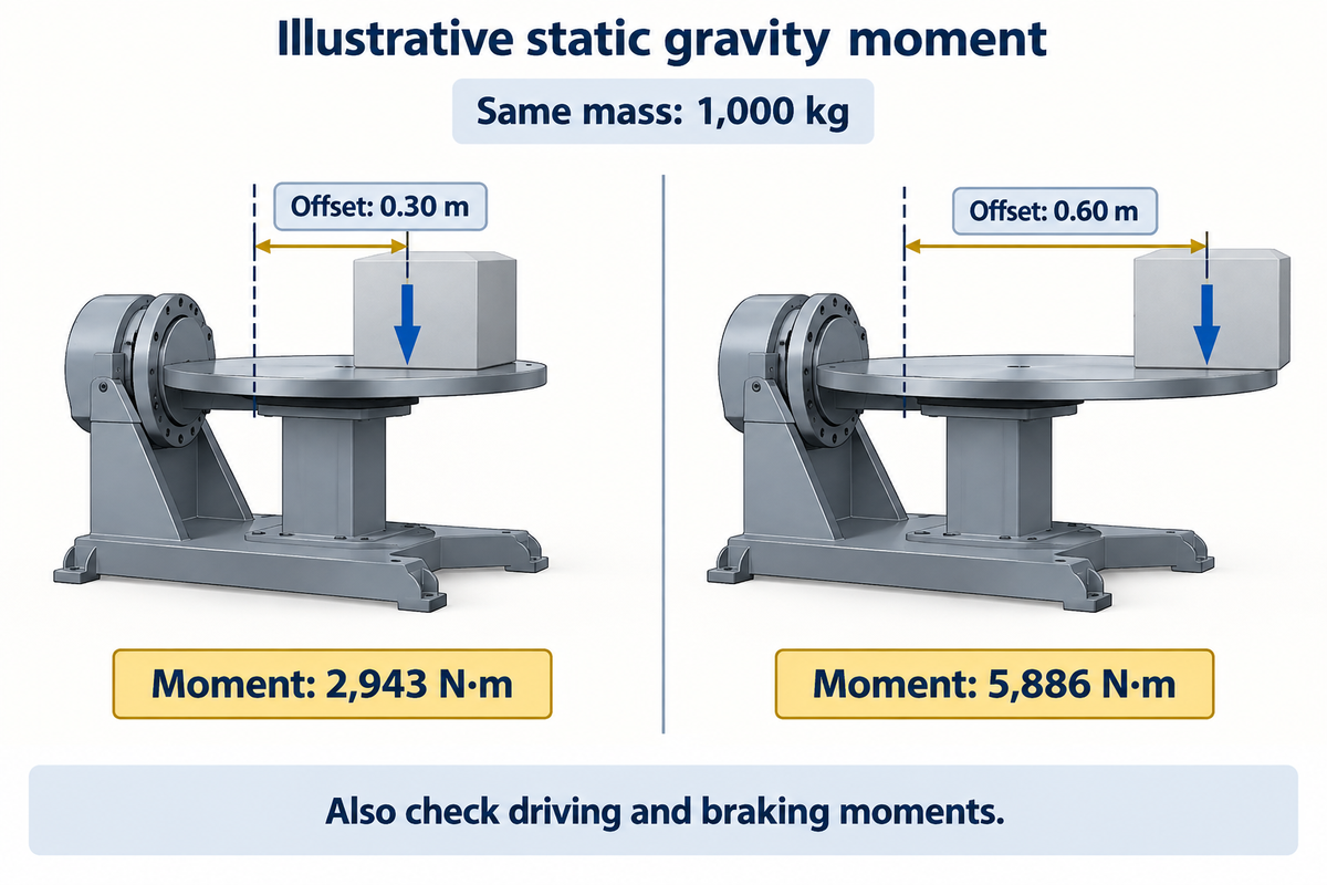
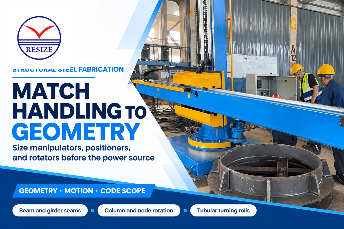
Choose a pipe welding rotator for cylindrical work that rollers can support and turn through its required motion. Choose a welding positioner for an assembly that can be securely clamped and oriented within the machine’s rated load envelope. The total mass, center of gravity, fixture load and clearance determine suitability.
Use the complete assembly drawing with elbows, flanges and temporary tooling.
The heaviest component isn’t always the most difficult to turn. A lighter spool with a large offset can impose a greater gravity moment and sweep a larger area than a heavier, nearly concentric cylinder.
UCLA’s definition of torque ( found here) defines torque as force multiplied by the perpendicular moment arm. In this worked example, a 1,000 kg assembly with a 0.30 m perpendicular offset has a static gravity moment of 1,000 × 9.81 × 0.30 = 2,943 N·m. At 0.60 m, it’s 5,886 N·m. For machine designs, gravity moments and loads are factors to be considered. Braking and driving moments must also be calculated.
| Actual work | Likely route | Check that changes the choice |
|---|---|---|
| Straight cylindrical spool | Welding rotator | Roller contact, load distribution and ability to turn without interference |
| Elbow or offset branch assembly | Clamped positioner or purpose-designed support arrangement | Center of gravity through the movement, fixture loads and floor clearance |
| Flanged spool needing reorientation | Welding positioner | Fixture connection, required tilt and access to each joint |
| Pipe that cannot rotate | Orbital head or another qualified fixed-pipe process | Head envelope, clamping length, joint access and procedure |
| Long assembly with a moving welding head | Manipulator combined with suitable supports | Loaded reach and whether each axis is specified for welding travel |
Let’s say a shop is making straight spools in one shift and elbow assemblies in the next. The goal of Production is to get a machine to make both in a given shift. Meanwhile, Procurement is comparing nominal kilogram ratings, and Engineering is concerned with an elbow moving the center of gravity away from the axis. The right comparison here’s a drawing that shows the two assemblies in their full range of motion, including the chuck and fixtures. If the elbow can’t clear the floor, or the loaded moment of the elbow assembly is greater than the selected machine’s rating, having a higher nominal payload doesn’t solve the problem. The buyer can keep the straight work on welding rotators and evaluate pipe welding positioners for the offset family.
Quick Specs: HBJ-12 Positioner
RESIZE’s published HBJ-12 row lists a 1,200 kg nominal load, 0.05–0.5 rpm rotation, 0–120° tilt and a 1,200 mm table. Match the complete assembly to the applicable loaded-position and center-of-gravity limits before selecting that model.
Orbital Welding or Rotating Pipe: Which Fits the Joint?
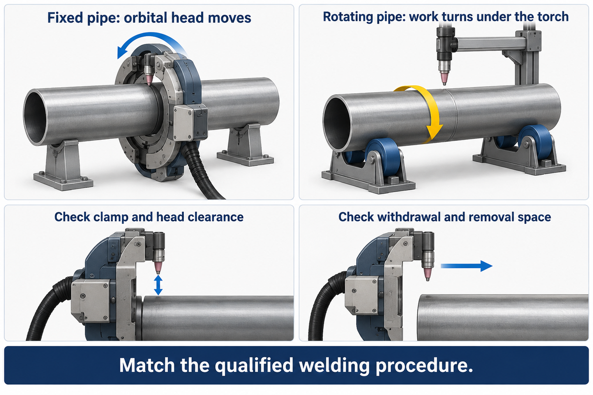
Use an orbital system when the pipe must be fixed and a compatible head can reach the joint; use a rotating pipe system when the work can turn underneath the torch. For either system, the head, joint preparation, filler requirements and qualified welding procedure must be matched to the actual application.
TWI’s orbital welding guide describes a tool moving through 360° around a static workpiece, with a 180° double-up variant. Welding a joint with a single technique doesn’t necessarily mean that the orbital head can weld all pipe materials, thicknesses, and types of joints.
A closed fusion head for an autogenous joint, made without any added filler metal, has a different job from an open head equipped for filler wire welding. A fixed pipe system may require control of arc voltage, oscillation and a specific cooling system. Specify the functions needed by the procedure and don’t consider the term “orbital” a complete equipment specification.
Access to the weld line may not be sufficient. Check the position of the clamp, the travel of the head around the joint, hoses and cables and how the head will be removed. Check the space needed to remove a rotating spool. For a rotating spool, consider the space needed for the entire assembly. A flange may leave a weld visible while obstructing a particular head or its clamping arrangement.
For example, a short joint between two closely spaced fittings may favor a compact head, but that conclusion must include the fixture and withdrawal path. Conversely, a long, straight spool with accessible cylindrical supports may be easier to rotate. Compare both arrangements on the same representative drawing, using the same weld acceptance requirements and the same loading boundary.
The orbital package should include its power and control unit, compatible heads, wire feed (if needed), cooling and program storage. The rotating route should include a positioner or rolls, welding package, and any synchronized controls. Identify each included accessory to ensure quotations cover the same work.
Pipe Beveling, Fit-Up and Stainless Steel Preparation
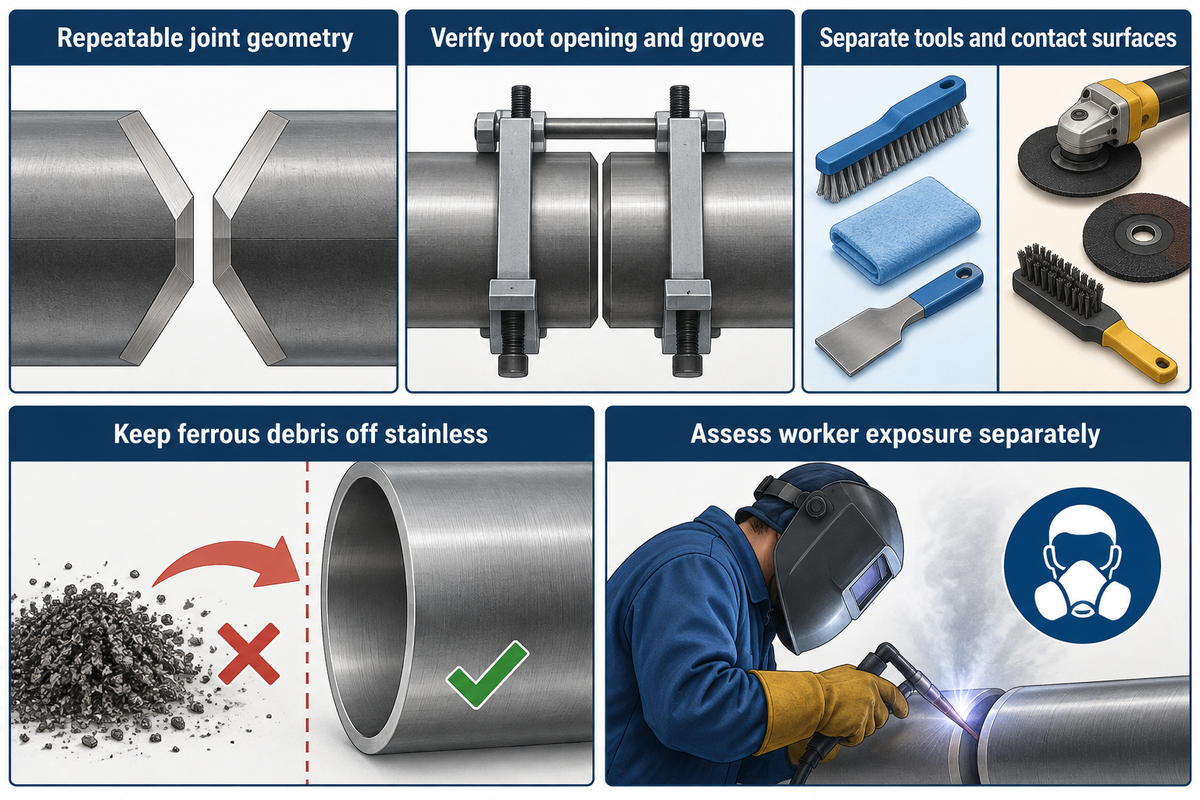
Welding automation relies on repeatable joint geometry, which depends on correct preparation. Select welding and cutting equipment, alignment fixtures and cleaning tools based on the actual pipe material and joint design, and measure their impact on the total cycle time. For stainless work, separate tools and contact surfaces that may introduce iron contamination and include appropriate exposure controls.
Check the root opening and groove geometry separately from consistency of the outside-diameter. Record the drawing and procedure requirements at fit-up, and the inspection method used to accept the prepared joint. Equipment that relies on a consistent seam can lose its apparent welding-time advantage while waiting for upstream rework. The Fabricator’s discussion of questions to ask before automating welding speaks to this fit-up constraint.
The British Stainless Steel Association’s contamination guidance warns against using equipment and tools shared with non-stainless steels without adequate segregation and cleansing. Ferrous grinding debris can also contaminate stainless surfaces. Brushes, abrasives and contact surfaces should be separated for the work and included in the work plan, along with the selected pipe beveling machines.
Picture a shop system with carbon steel tasks and a stainless steel spool system. The plant manager notes the available floor space and proposes sharing the same preparation bench. Quality sees a different cost. Cleaning and handling may need to be repeated to prepare the stainless steel joint. A dedicated preparation kit and controlled storage may be a more useful first purchase than another welding head. Measure the time and work spent on repeated cleaning in that configuration. The example is a planning scenario, not a measured RESIZE project or a claim that every shared bench produces the same defect.
Worker exposure is a different concern from surface cleanliness. Where chromium (VI) exposure falls within OSHA 1910.1026, the employer must determine exposure through an applicable assessment path and implement the required controls. Budget the assessment and control for the actual work; this isn’t a universal ventilation-size or gas-purity prescription.
Sour Service: MR0175 vs MR0103 and Welding Controls
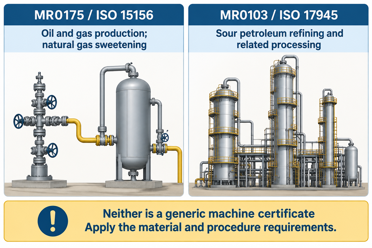
MR0175/ISO 15156 and MR0103/ISO 17945 address different sour-service material environments. The first covers stated oil and gas production and natural gas sweetening; the second covers petroleum refining and related processing. Neither is a generic product certificate for a welding rotator, positioner or manipulator.
AMPP’s public MR0175/ISO 15156 scope addresses metallic materials in specified hydrogen-sulfide-containing environments. It supplements relevant design-code material requirements and is not necessarily applicable to refining or downstream equipment. The separate MR0103/ISO 17945 scope concerns resistance to sulfide stress cracking in sour refining service and expressly excludes design specifications.
For procurement, connect the service requirements to the material and welding procedure before selecting equipment functions. If the procedure calls for controlled preheat, interpass temperature, heat treatment or particular records, assign each function to the welding package, ancillary equipment or shop process. Do not infer a universal hardness, temperature or heat-input limit from the phrase “sour service.”
A quality lead assessing a proposed cell requires a different answer from a buyer comparing motor power. Quality requires the specified procedure and acceptance route to be reproducible; production requires a workable way to carry out and record them. A welding control screen with program storage can help repeat settings. Assess welding procedure qualification and finished-weld acceptance requirements separately.
Does welding equipment for oil and gas pipelines need to be certified?
Yes, when the specific requirements for a product, workplace, or project stipulate the need for equipment certification. Welding procedures and personnel have their own qualification requirements. Specify the required evidence for a machine, welding procedure, operator and finished weld, separately, to avoid substituting a machine certificate for procedure or personnel qualification.
For US pipelines, the provisions in 49 CFR 195.214 and the gas-pipeline provisions in Part 192 stipulate their respective procedure requirements. Purchasing an oil and gas machine doesn’t fulfill those requirements. Specify the pertinent requirements in the equipment purchase specification so the demonstration tests the intended joints and processes.
Timing of inspection is also part of the process plan. PHMSA’s historical construction investigations describe delayed hydrogen-assisted cracking in certain high-strength pipeline welds which earlier examinations hadn’t revealed. The applicable inspection and release requirements govern inspection timing; the report doesn’t prescribe a universal waiting period for all shop spools.
Pipe Spool Welding: Find the Constraint Before Automating
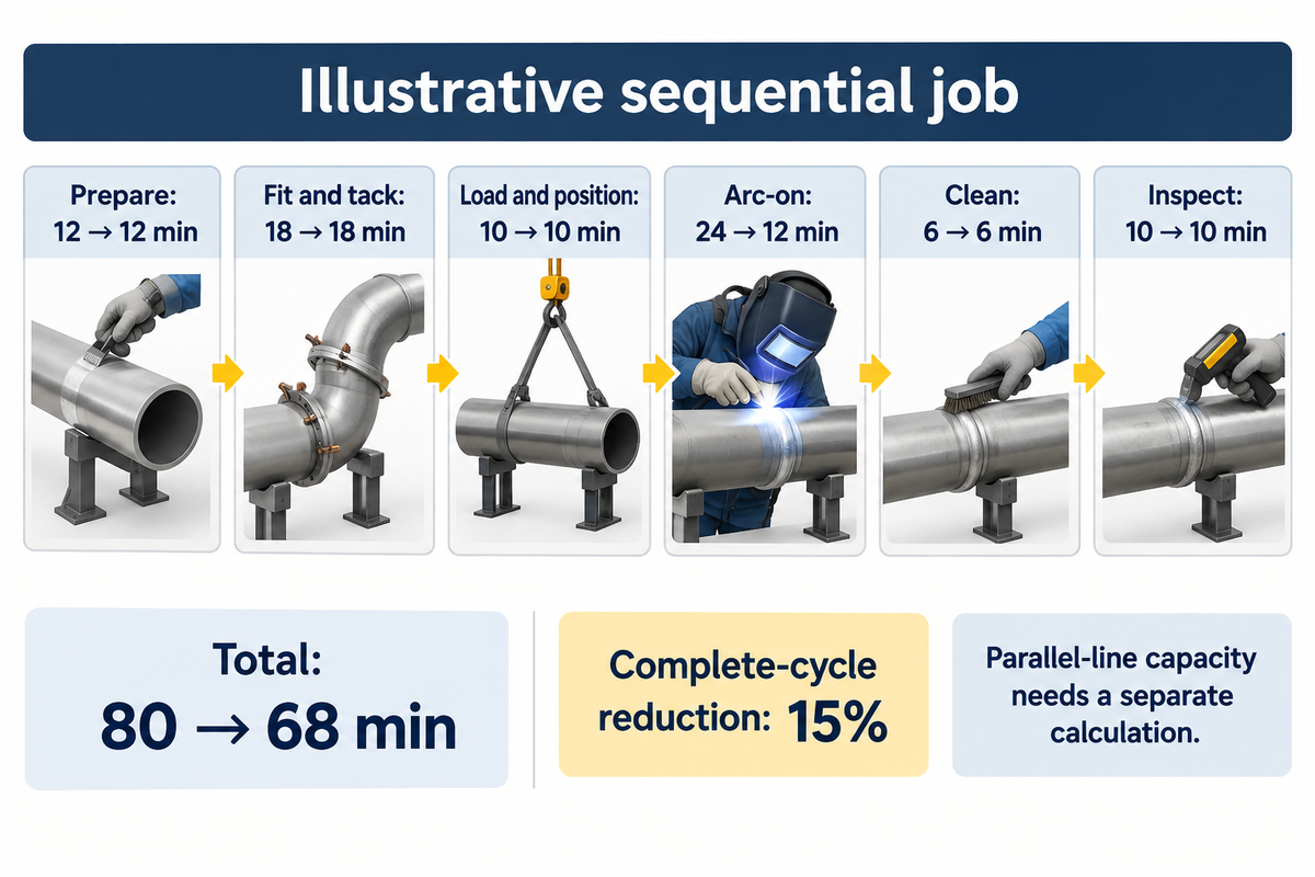
Measure the time required for each activity in the complete spool production process before implementing automation. There are multiple activities that can cause a holdup, including preparation and fit up; loading; welding; cleaning; and inspection. Mapping the spool production cycle helps a plant manager identify activities that may combine to lengthen the cycle.
In The Fabricator’s welding-throughput guidance, Hobart engineer Robert Fox recommends a time study that begins before the first arc, and considers upstream and downstream work. Apply that boundary consistently to both alternatives. A demonstration timed from the first arc can’t rightly be compared to a manual job timed from material retrieval.
| Stage | Current minutes | Faster-arc minutes | Constraint to watch |
|---|---|---|---|
| Prepare | 12 | 12 | Clean, accepted joint ready |
| Fit and tack | 18 | 18 | Repeatable alignment and gap |
| Load and position | 10 | 10 | Fixture change and lifting availability |
| Arc-on welding | 24 | 12 | Procedure and joint capability maintained |
| Clean after welding | 6 | 6 | Access and required surface condition |
| Inspect within the chosen boundary | 10 | 10 | Qualified resources and release requirements |
| Total | 80 | 68 | 12 minutes saved per sequential job |
The calculation is 12 + 18 + 10 + 24 + 6 + 10 = 80 minutes. Cutting arc time in half yields a total cycle time of 68 minutes, a 15% reduction in this complete sequential cycle. A line with parallel stations requires a separate capacity calculation based on the limiting station, staffing, and available production time.
Suppose the welding station finishes sooner, but the same lifting resource has to unload finished work and feed the next spool. Production may see a queue at the crane while the welder waits next to an available machine. Finance can’t turn that idle time into payroll savings. The next meaningful change may be improving staging arrangements or fixture changeover, followed by a new measurement across the same boundary. Distinguish elapsed time from person-time. Two people working for ten minutes consume twenty person-minutes, but the job still takes ten elapsed minutes. Making this distinction prevents the time study from becoming a false claim for a great improvement in labor savings.
A 2025 University of North Dakota study of high-mix, low-volume welding investigates that setting. Judge the work mix and reusable setups to determine the automation viability. The Fabricator recommends assessing the processes upstream and downstream before treating welding speed as the production constraint. Examine the measured sequence of work of your shop and judge potential savings. Connect the sequence to the pipe welding manipulator and neighboring workstations.
Pipe Welding Machine Price and Payback at Low Volume
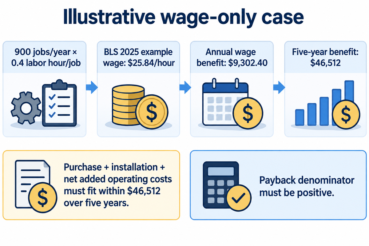
Compare the price of a pipe welding machine on an installed, usable scope, and calculate savings from the annual work volume you can actually assign to it. A low equipment price may exclude fixtures, controls or commissioning. A large claimed time saving may produce little cash benefit if labor can’t be redeployed or avoided.
Price welding equipment and supplies separately, with distinct allowances for handling, the welding power package, tooling, system integration, utilities, training and support. Include the applicable workplace-control work identified during layout planning. The baseline questions in The Fabricator’s automation discussion are useful here: what does the shop make, how is it made now, and which part of that activity can change?
For a public US price reference, integrator KC Robotics lists pre-engineered robotic welding cells at $85,000–$180,000 and custom systems at $200,000–$350,000+ in its 2026 guide. These are that supplier’s general robotic-cell ranges, not installed pipe-spool cell quotations or prices for RESIZE handling machines. Part presentation, fixtures, head access, coordinated movement and site integration determine which scope the buyer is comparing.
A budget assessment of the work is a good first estimate. The US Bureau of Labor Statistics lists $25.84 per hour as 2025 median pay for welders, cutters, solderers and brazers. Use that published wage as a transparent illustration, then substitute the shop’s avoidable labor cost. It’s a broad occupational wage, not a fully burdened rate or a pipe-welder-specific quote.
The following sensitivity example assumes 300, 900 or 1,800 jobs per year and realized labor reductions of 0.2, 0.4 or 0.6 hour per job. Those volumes and reductions are planning inputs, not measured customer results. The chosen 5-year horizon is a planning horizon. This financial scenario is different from the elapsed-time example previously shown.
Five-year incremental cost worksheet
| Cost item | Input to collect | Scope to include |
|---|---|---|
| Purchase price | Quoted equipment amount | Handling, welding package, fixtures and controls |
| Installation & commissioning | Quoted installed work | Utilities, integration, workplace controls, training and acceptance |
| Energy over the planning period | Change in consumption × local tariff | Production and relevant standby operation |
| Maintenance & spares | Incremental service and parts expense | Planned service and expected replacement parts |
| Downtime cash expense | Incremental cash effect of interruptions | Avoid counting lost output again as labor expense |
Add purchase and installation to the operating-cost changes over the selected horizon. Compare that total with the labor benefit below. Any positive incremental operating expense reduces the amount available for the initial purchase and installation.
At 900 jobs/year and 0.4 labor hour/job saved, annual wage benefit = 900 × 0.4 × $25.84 = $9,302.40/year. Across 5 years, that’s $46,512. On this wage-only basis, purchase, installation and net additional operating expense together must fit within $46,512 to break even over the chosen period. This is an affordability test, and not an estimate of the equipment price.
| Annual jobs | Labor saved per job | Annual wage benefit | 5-year benefit before incremental costs |
|---|---|---|---|
| 300 jobs/year | 0.2 hour/job | $1,550.40/year | $7,752 |
| 300 jobs/year | 0.4 hour/job | $3,100.80/year | $15,504 |
| 300 jobs/year | 0.6 hour/job | $4,651.20/year | $23,256 |
| 900 jobs/year | 0.2 hour/job | $4,651.20/year | $23,256 |
| 900 jobs/year | 0.4 hour/job | $9,302.40/year | $46,512 |
| 900 jobs/year | 0.6 hour/job | $13,953.60/year | $69,768 |
| 1,800 jobs/year | 0.2 hour/job | $9,302.40/year | $46,512 |
| 1,800 jobs/year | 0.4 hour/job | $18,604.80/year | $93,024 |
| 1,800 jobs/year | 0.6 hour/job | $27,907.20/year | $139,536 |
To calculate simple payback, subtract annual net additional operating expense from annual realized labor savings and divide purchase plus installation cost by the result; the denominator must be positive. An owner with a small order book may find that a handling improvement fits available benefits better than a complete automated cell. Count freed time only when it reduces cost or supports a separately evidenced commercial benefit; do not count the same hours again as extra capacity sales. This model doesn’t consider tax, finance, resale, time value of money.
Welding Rotator Manufacturers and Orbital System Suppliers
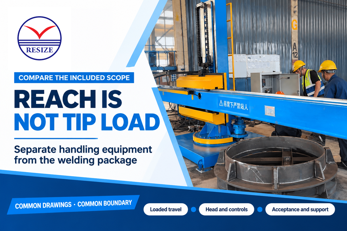
Compare manufacturers of welding rotators and suppliers of orbital systems on the function they perform and the integration work included. A handling-equipment quotation, a welding-head package and a complete cell solve different parts of the job. Give the suppliers the same set of spool drawings and demonstration requirements, then compare total prices.
RESIZE publishes rotators, positioners, and manipulators. Its HGZ-20 rotator table lists a nominal maximum load of 20 t and a roller linear speed of 6 to 60 m/h, measured as linear travel rather than revolutions per minute. The NLH heavy duty manipulator series has stroke ranges of 2,000 to 8,000 mm in both the vertical and horizontal axes. Use the stroke figures to assess reach, and check the rated tip load at maximum reach.
Polysoude offers orbital welding in various configurations including closed-chamber heads, open heads, and carriage-type heads, according to its published literature. Its application examples include filler-wire welding of carbon-steel pipe. Compare the extent of that welding-package scope to RESIZE’s handling-equipment scope when divvying up a cell. TWI’s equipment-component description provides detail on the controller, head, and optional wire-feed function. The positioner selection factors concern the complete moving assembly.
Use the recommended ranges of the jobs when filling in the request for quotation form. The recommended ranges aren’t the universal ratings for the machines.
Request-for-quotation checklist
| Parametru | Recommended range | De ce contează | How to verify |
|---|---|---|---|
| Pipe and joint geometry | Actual outside diameters and walls, mm | Defines preparation, head and fixture needs | Use representative drawings and joint samples |
| Complete moving load | Job mass in kg; center-of-gravity offsets in mm | Nominal mass alone misses moment demand | Match fixture-inclusive loads to rated diagrams |
| Movement and space | Required tilt in degrees; swept dimensions in mm | Interference can prevent completing the weld | Check the complete movement and withdrawal path |
| Welding package | Procedure-required process and operating range | Separates handling from weld capability | List included power, head, feed, gas and cooling functions |
| Work mix and volume | Jobs/year and measured labor hours/job | Sets utilization and financial sensitivity | Use the production schedule and a shared time-study boundary |
| Acceptance and support | Project-specific tests, records and delivery schedule | Defines what the installed system must deliver | Agree representative-part demonstration and handover items |
Industry Outlook: Welding Equipment Qualification
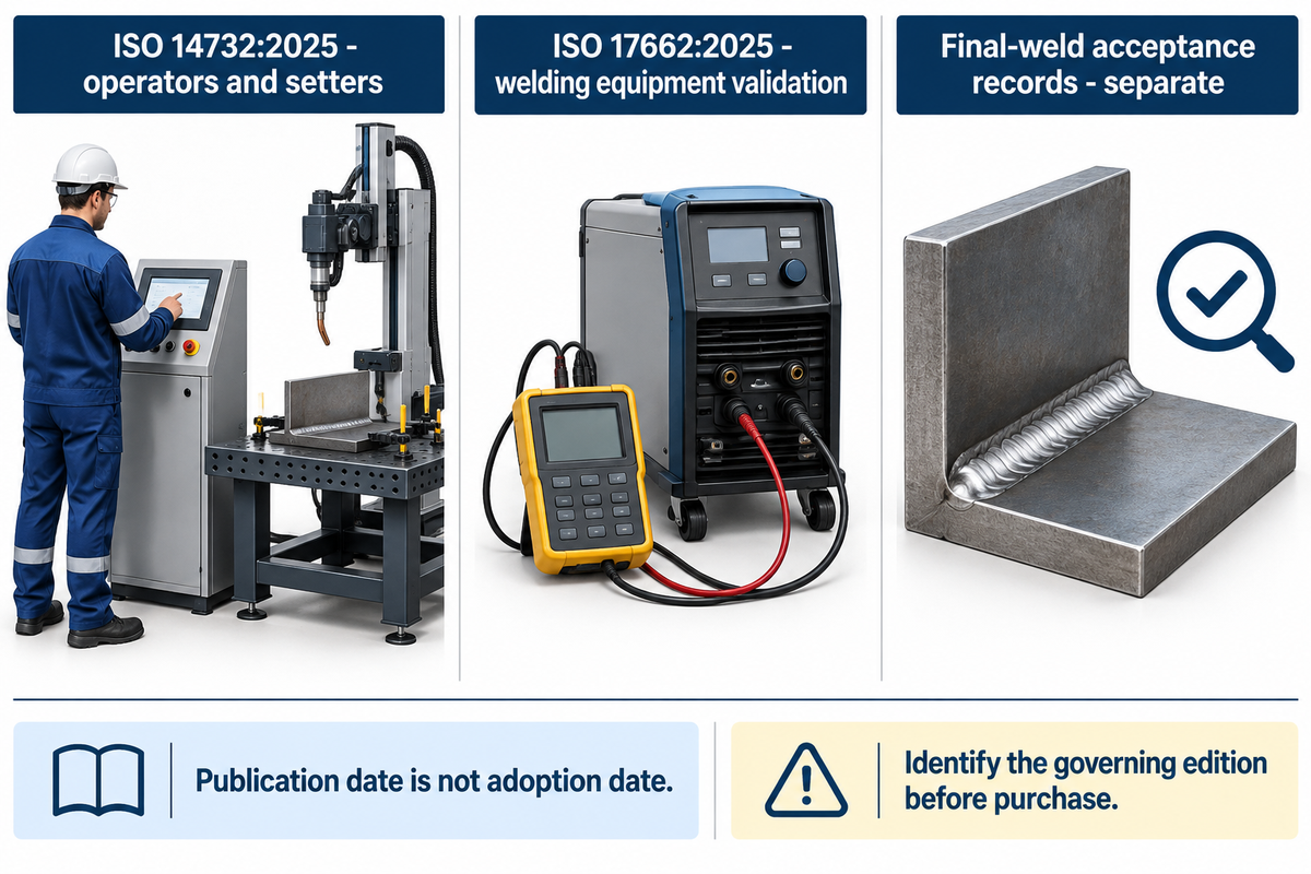
Recent qualification standards make the scope of a welding-cell purchase more specific: personnel qualification and equipment validation need separate attention. ISO published new editions of ISO 14732 and ISO 17662 in 2025. For a new project, identify which edition of the standards governs and what evidence the supplier has to provide.
ISO 14732:2025, published in June 2025, addresses qualification of welding operators and setters for mechanized and automatic welding of metallic materials. Its scope concerns the people controlling parameters or setting up equipment. Certification of equipment, however, does not answer this personnel question.
ISO 17662:2025, published in September 2025, addresses calibration, verification and validation of equipment used for welding and associated activities within its scope. It covers equipment used in production or on site and excludes the manufacture and installation of new equipment. It also excludes calibration requirements for equipment used in final welded-product inspection and testing.
Publication date and mandatory adoption date are different facts. ASME’s catalog lists Section IX in a 2025 edition; where 49 CFR 192.7 incorporates an older edition for an applicable provision, that incorporated edition governs the regulatory reference. A newer catalog listing doesn’t automatically replace the edition adopted by a regulation or contract.
For a purchase planned now, turn those distinctions into deliverables: point out the required procedure and personnel qualification route, enumerate equipment variables that need validation, and separately list final-weld acceptance records. Assign responsibility for each before commissioning. This enables procurement to compare documentary and training scope without treating each new standard edition as a reason to replace a working machine.
Întrebări frecvente
What are the different positions of pipe welding?
The arrangements covered here are rotating pipe and fixed pipe with a vertical, horizontal or inclined axis.
A rotating arrangement lets the torch stay at a selected location while the joint passes beneath it. For a circumferential butt weld on fixed pipe, a vertical pipe axis keeps welding in the horizontal position; a horizontal or inclined axis requires changing welding positions as the torch travels around the joint. The procedure and personnel qualification must cover the required position. Select handling and access around that requirement.
What type of welding is commonly used for pipelines and steel beams?
Stick, TIG and wire-fed processes are used in industrial welding; the suitable choice follows the joint and qualified procedure.
A pipeline root pass and a structural beam connection have different access and production requirements. They shouldn’t be assigned the same equipment package merely because both involve steel. For pipe fabrication, establish the joint material, wall, position and acceptance requirements, then compare the complete welding outfit and handling method. Structural-steel requirements don’t automatically apply to a pressure-piping job.
What tools do pipelayers use?
Pipelayers use lifting, alignment, measuring and preparation tools suited to the pipe and installation method.
A welded steel installation also needs the specified welding package and the equipment required to handle prepared joints safely. A fabrication shop adds repeatable fit-up stations, supports and fixtures for spool production. Site installation has a different movement and access problem from shop work, so excavation or field-handling equipment shouldn’t be confused with a shop’s welding positioner or orbital-head package.
Can orbital welding be used for carbon-steel pipe?
Yes, with a system suited to the joint, material, wall and required procedure. A closed head intended for autogenous tubing joints differs from an open filler-wire system. Select the head and process package for the application, including access and joint preparation.
What spool information should accompany an equipment quotation?
Send the drawing, material, outside diameter, wall thickness, complete moving mass and center of gravity, including fixtures. Show each joint and the assembly through its required movement. Add the welding procedure requirements, annual job mix, measured cycle boundary, available utilities, lifting arrangements and floor space. Ask the supplier to separate handling, welding, controls, installation, training and support. Include the representative-part demonstration and delivery schedule so competing offers cover the same work.
Plan Your Pipe Spool Equipment Package
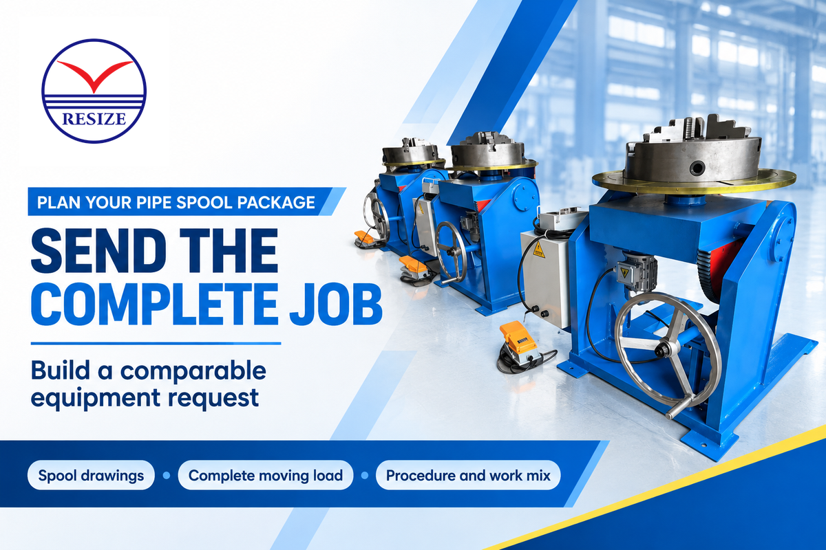
Choose the motion route based on the complete spool geometry, measure the entire job, and assess the installed scope against the usable annual volume. Send your spool drawings and completed quotation fields for the rotator, positioner or manipulator section of your welding cell for our review.
Related Reading
Referințe și surse
- 29 CFR 1910.252(a)(2)(ii)
- 49 CFR 192.225
- ASME B31.3
- UCLA’s torque explanation
- TWI’s orbital welding guide
- questions to ask before automating welding
- British Stainless Steel Association’s contamination guidance
- OSHA 1910.1026
- MR0175/ISO 15156 scope
- MR0103/ISO 17945 scope
- 49 CFR 195.214
- PHMSA’s historical construction investigations
- The Fabricator’s welding-throughput guidance
- 2025 University of North Dakota study of high-mix, low-volume welding
- Bureau of Labor Statistics lists $25.84 per hour as 2025 median pay
- ISO 14732:2025
- ISO 17662:2025
- Section IX in a 2025 edition
- 49 CFR 192.7