Updated August 2026
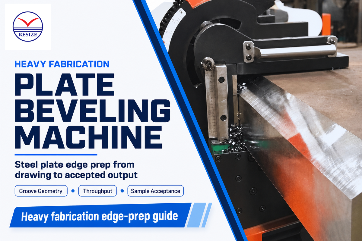
A plate beveling machine is a machine tool that cuts a controlled groove face on a plate edge prior to welding. For heavy fabrication, choose it from the groove that must be accepted, the meters and feet required per shift, the way each plate will be handled, and the inspection evidence the buyer needs. Maximum plate thickness and headline feed speed are only two inputs; neither predicts how many weld-ready edges will leave the preparation area without rework.
This guide begins where a general equipment primer ends. If you first need the basic differences among plate beveler types and edge-preparation methods, use RESIZE’s plate beveler introduction. Here, the task is narrower: convert a heavy-plate drawing into a production requirement, a representative trial, and a quotation that can be compared across suppliers.
Don’t ask only, “Can the machine cut this thickness?” Ask, “Can the proposed system produce this groove on our plate, under our handling and safety conditions, at an accepted rate we can verify?”
For a commercial configuration review, the requested internal destination is RESIZE’s range of milling and beveling machines. That public page is a starting point for discussion, not a substitute for a model-specific quotation.
Freeze the Heavy-Plate Production Requirement
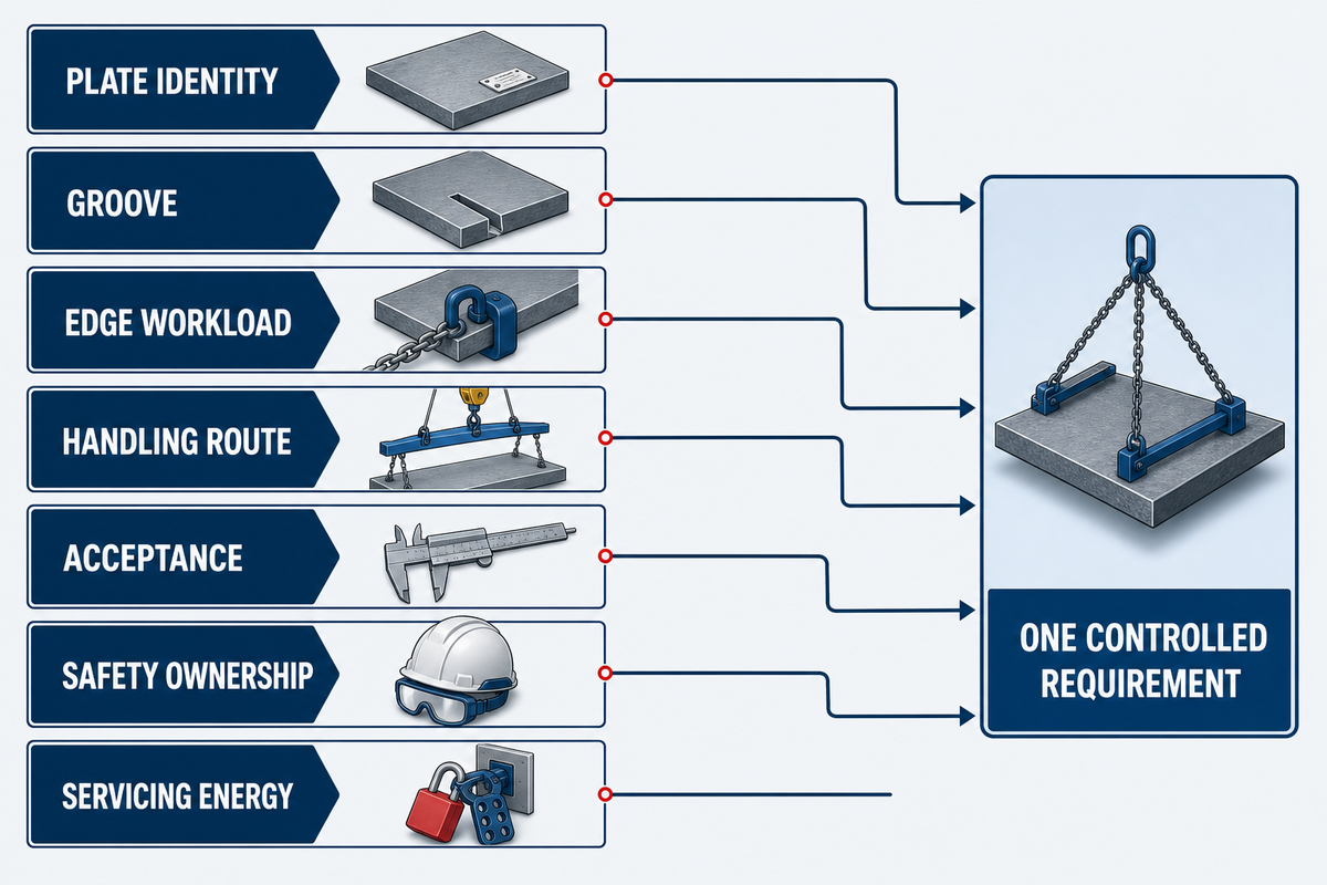
Useful requirements fix the workpiece, groove, workload, handling route, acceptance method, and safety ownership before equipment is compared. This prevents a supplier from quoting a machine that reaches the nominal angle but can’t support the actual edge length, pass strategy, or inspection plan.
Start with the drawing and the applicable welding procedure. ISO’s official scope page for ИСО 9692-1:2013 shows why “standard bevel” is not a complete instruction: preparation depends on the welding process and joint conditions, and the published scope includes important boundaries. Project drawings, procedures and contracts still own the actual geometry.
| Requirement field | What to state | Why it changes the decision | Evidence owner |
|---|---|---|---|
| Plate identity | Grade, thickness range, hardness or condition when relevant, coatings, edge condition | Machinability, insert choice, pass count and finish can change | Buyer material record |
| Паз | Angle, root face, depth, root opening context, upper/lower edge, one- or two-side access | Defines removed metal and the machine route | Drawing and welding procedure |
| Edge workload | Metres per plate, plates per shift, lot mix, changeovers | Separates intermittent work from a scheduled production cell | Production planning |
| Handling route | Plate mass and dimensions, lift points, supports, turnover, transfer path | Can dominate cycle time and restrict two-side work | Plant and safety teams |
| Acceptance | Measurement points, instruments, drawing tolerances, fit-up check, rework disposition | Turns a machined edge into an accepted production result | Quality assurance |
| Guarding | Point-of-operation, rotating-part, chip and spark controls | Safety is a prerequisite, not a throughput trade | Employer and competent safety review |
| Servicing energy | Isolation responsibility for insert service, cleaning, adjustment and maintenance | Defines how intervention is performed and timed | Employer procedure and machine instructions |
In the United States, 29 CFR 1910.212 requires one or more guarding methods against hazards that include the point of operation, rotating parts, flying chips and sparks. That establishes a general boundary; it doesn’t prove that any particular machine, layout or work practice complies.
“Properly preparing metal for welding is key to producing high-quality results, maintaining consistent productivity levels, and minimizing costs.”
— Rick Hopkins, a manufacturer-affiliated contributor writing in The Fabricator
Assign ownership before the trial. Production can own workload and changeover data; welding engineering can own the controlled groove; quality assurance can own the measurement plan; safety personnel can review the operating zone and intervention method; procurement can own the comparable return format. If one of those owners is missing, the supplier will usually fill the gap with a product assumption, and different quotations will no longer describe the same job.
Also separate a maximum from a working requirement. Maximum cutting depth is a boundary published for a machine family or model. Production requirements specify the depth, pass count and repeatability needed on a named plate under a named setup. Quotations should show the margin between the required point and the quoted operating point, but the buyer shouldn’t invent a “safe percentage” without model-specific evidence.
Convert Groove Geometry into Removed Metal and Weld Volume
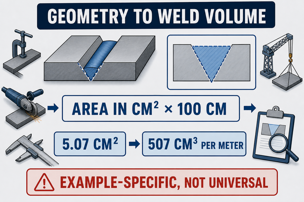
Groove geometry is the bridge between edge preparation and downstream welding work. Angle, root face, depth, root opening context and side access change the cross-sectional area to be machined and filled. A machine’s maximum plate thickness can’t reveal that workload by itself.
Planning works in two stages. First, calculate the groove cross-sectional area from the drawing. Next, multiply that area by the total weld length. TWI’s weld-volume method and worked example illustrate the sequence with explicit geometry rather than a generic percentage.
Geometry-to-Weld-Volume Worksheet
- Copy the plate thickness, included angle, root face, root opening context and cap allowance from the controlled drawing or procedure.
- Break the cross-section into simple shapes and calculate the total area in one unit system.
- Calculate volume per meter: cross-sectional area in cm² × 100 cm.
- Multiply by total weld length, then compare candidate preparations using the same assumptions.
- Add plate turnover, second-side datum/setup, extra passes and access limits before making a cost decision.
For TWI’s stated single-V inputs, the calculated area is 5.07 cm². Over one meter, the volume is 5.07 cm² × 100 cm = 507 cm³ per meter. Use the method with your drawing; don’t reuse the result as a universal groove value.
This worksheet also prevents a common purchasing error. In a fixed geometry, a double-sided preparation may reduce groove area, yet it introduces reverse-side access, plate turnover and a second setup. When those steps are slow or unsafe, lower weld volume doesn’t automatically mean lower total cost.
How do you turn groove geometry into a heavy-plate trial brief?
Choose the route after converting the required groove into bevel depth, width, pass count and side access. Then check whether the plate moves to the machine or the machine travels along the plate, whether the underside is reachable, and whether the proposed tool can hold the required geometry on the actual material. That analysis produces a sample-run brief, not a model choice made from thickness alone.
The 7-Station Bevel Throughput Map
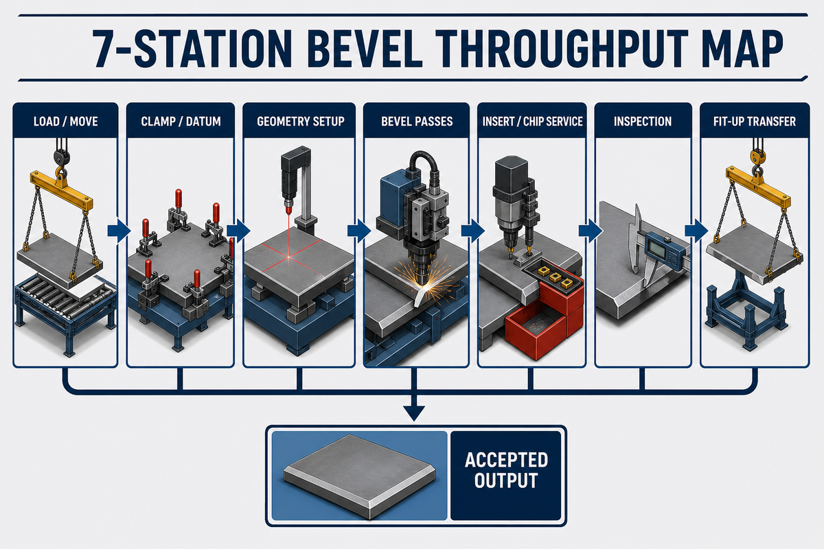
This 7-Station Bevel Throughput Map measures the whole job from plate movement to fit-up transfer. It’s a buyer-use diagnostic snapshot, not an industry standard. The limiting station can move when plate geometry, lot size, tool condition, inspection load or queue state changes.
Published feed speed describes motion while cutting under stated conditions. Accepted output subtracts interrupted work, rework and rejected edges and includes the time required to make the next plate ready. Plants that time only the cutter may buy enough spindle capacity but too little handling, inspection or tool-service capacity.
| Station | Clock starts | Clock stops | Record with | Failure signal |
|---|---|---|---|---|
| 1. Load / move | Plate requested | Plate at working position | Minutes and handling crew | Machine waiting for plate |
| 2. Clamp / datum | Plate positioned | Datum and support accepted | Minutes, supports, re-clamps | Angle drifts after movement |
| 3. Geometry setup | Job setup begins | Trial cut accepted | Minutes and adjustment count | Repeated trial cuts |
| 4. Bevel passes | Cut begins | Required edge completed | In-cut minutes, meters, passes | Feed interruptions or recuts |
| 5. Insert / chip service | Cut is stopped | Safe cutting resumes | Minutes and insert event | Burr, chatter or finish change |
| 6. Inspection | Edge presented | Disposition recorded | Minutes, points, result | Queue or late rejection |
| 7. Fit-up transfer | Accepted edge released | Next operation receives it | Minutes and fit-up observation | Preparation accepted but fit-up fails |
For a single sequential work area, add the station times to understand total cycle time. For a line with parallel stations, compare sustainable station capacities and watch queues. In either layout, repeat the measurement when the groove, plate family or staffing pattern changes.
How to read one trial without creating false precision
Suppose a hypothetical 12 m plate takes 8 minutes to move, 5 to support and clamp, 7 to set and accept the trial geometry, 18 for all bevel passes, 4 for tool and chip service, 6 for inspection and 5 for transfer. The sequential cycle took 53 minutes, not 18. Cutting time of 18 minutes is still useful, but it isn’t the job cycle. On another material, insert service could rise and become the longest element; on a small lot, setup may dominate.
Run the map on several representative plates, not one showcase edge. Record the median, the slowest accepted cycle, the cause of every interruption and the conditions that changed. Its purpose isn’t to promise a statistically universal rate. It’s to reveal which station needs more capacity, another work method or a clearer acceptance rule before money is committed.
Accepted meters = processed meters − meters rejected or sent for rework.
If a hypothetical shift costs $2,400, processes 120 m (394 ft), sends 8 m (26.2 ft) to rework and rejects 4 m (13.1 ft), accepted output is 108 m (354 ft) and cost per accepted meter is $2,400 ÷ 108 = $22.22/m. Buyers using US customary units should convert every length and normalized rate consistently. Replace every input with plant data; this isn’t a RESIZE performance or cost claim.
Long Heavy Plates Expose Feed, Clamp, and Flatness Errors
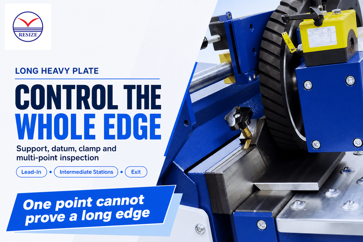
Long production bevels amplify small setup changes. Support height, plate flatness, datum choice, clamp movement, lead-in and lead-out behavior, chips and insert condition can change along the same edge. One acceptable measurement near the start doesn’t describe the entire run.
TWI notes that single-sided joints require dimensionally accurate preparation and fit-up. That supports checking more than an operator’s visual impression, but it doesn’t prescribe one universal number of inspection points. Buyers should define measurement stations from the drawing, risk, edge length and quality plan.
Trial records should also name the material grade and condition, tool geometry, insert edge or index position, milling strategy, pass count, burr state and observed wear. Without these fields, a later feed-speed comparison may confuse a material or tooling change with a machine-capacity change.
Use fixed locations for a practical long-edge check so each point can be found again after the plate move. Mark the start, lead-in transition, selected intermediate stations, any interruption location and the exit. At each point, record the dimensions required by the buyer’s plan and note the support/clamp state. If a deviation begins after a re-clamp or an insert event, the record gives the team a testable cause instead of a vague conclusion that the machine “lost accuracy.” Point count and spacing remain project-specific.
What are common beveling mistakes on long plate?
Costly mistakes usually come from missing controls rather than one wrong dial: insufficient support, a datum that moves after clamping, an unrecorded plate condition, an insert used past its stable edge life, chip buildup, feed interruption, inspection at only one convenient location, or release without a fit-up observation. Treat each as a trial variable and record what changed before the next run.
Single-Side, Double-Side, and Multi-Pass Routes for Thick Plate
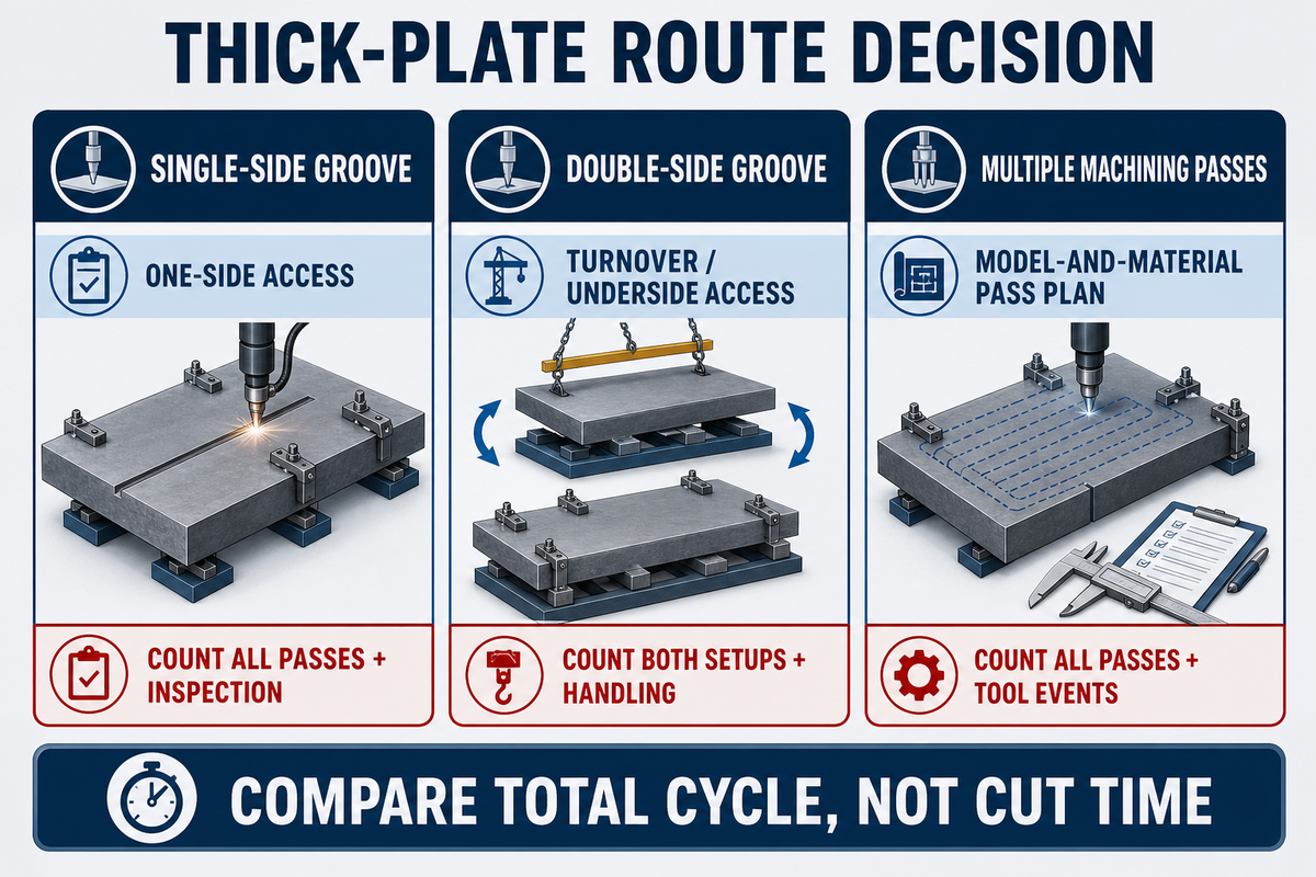
Route selection balances groove volume against access and handling. Single-side preparation avoids turnover but may require more removed and deposited metal. Double-side work may reduce cross-sectional area, yet it adds reverse-side access, a second datum and another handling cycle. Multi-pass machining may be necessary when the required depth exceeds a stable single-pass condition for the quoted model and material.
| Route | Precondition | Likely hidden work | Proof to request |
|---|---|---|---|
| Single-side groove | One-side access and drawing-defined geometry | Greater area, deeper preparation or more weld work in some geometries | Pass count, geometry map and fit-up |
| Double-side groove | Safe turnover or underside access | Second setup, datum recovery and handling queue | Two-side trial with total cycle time |
| Multiple machining passes | Model/material-specific pass plan | Tool service, chip clearing and cumulative geometry change | Per-pass record and final multi-point inspection |
Don’t convert these routes into a universal thickness threshold. Controlled drawings, required penetration, material, proposed tooling and handling systems must be evaluated together. Suppliers should explain not only which route they propose but also what the buyer must measure to accept it.
For each route, calculate two separate workloads. First comes geometry: removed cross-section multiplied by edge length. Second comes operation: handling, setup, all passes, tool service and inspection. This prevents a smaller groove from automatically winning when the plant can’t access the reverse side efficiently. It also prevents a single-side route from winning merely because turnover is inconvenient when the downstream weld volume is commercially dominant.
Match Machine Architecture to Heavy-Plate Flow and Handling
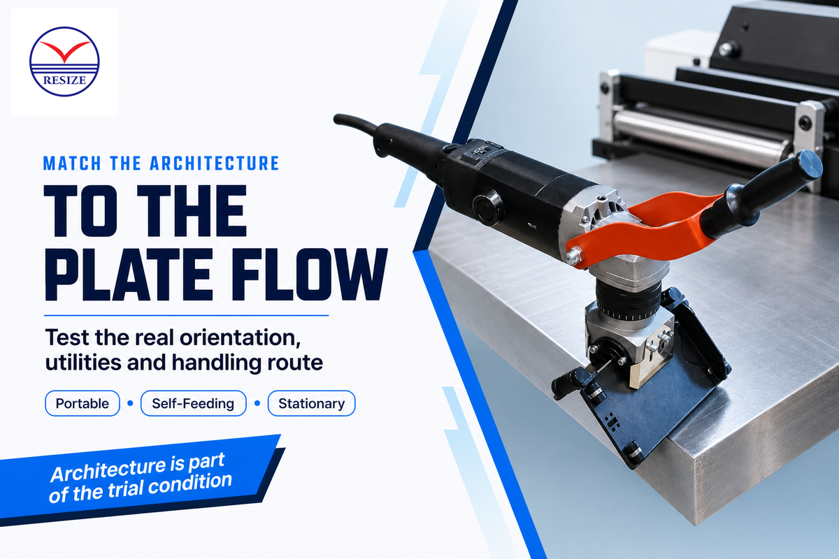
Machine architecture should follow the workload and movement constraint. Portable equipment brings the tool to a plate that’s difficult to relocate. Self-feeding equipment reduces continuous operator propulsion on repeat straight edges. A stationary edge-milling cell brings the plate into a controlled production area where support, feed and transfer can be planned as part of the line.
| Architecture | Workload evidence | Not suitable when | Trial proof |
|---|---|---|---|
| Portable / handheld | Intermittent edges, access-led work, machine must go to plate | The job demands repeat long-edge output without operator-propelled variability | Ergonomics, edge consistency, setup and accepted meters |
| Self-feeding | Recurring straight edges with a stable travel path | Plate condition, access or support prevents stable travel | Start/stop behavior, path stability, tool events and geometry map |
| Stationary edge milling | Scheduled heavy-plate flow with planned loading and transfer | Handling and floor-space constraints exceed the plant’s cell capacity | Total cell cycle, support/clamping, utilities and downstream transfer |
Normalize supplier terminology before comparing equipment
Supplier documents may use plate bevelling, plate bevellers or the singular beveller for the same purchasing conversation. They may group portable beveling machines under heavy duty, heavy-duty or heavy duty beveling. Treat those labels as indexing vocabulary. Ask for the machine model, plate condition, supported geometry and test evidence instead of awarding points for a stronger adjective.
Search and catalog language may also use portable plate beveler, handheld plate beveler, steel plate beveler or plate chamfering machine. Those phrases can describe overlapping product families. Normalize them to the actual architecture, tool motion, material scope and acceptance evidence before comparing quotations.
Tool descriptions also need normalization. A rotary machine may list a milling head, rotary milling head, carbide, carbide inserts, an indexable cutter or replaceable carbide. Record the exact head, insert grade, available cutting edges and service method. “Infinitely adjustable” or “adjustable bevel angle” describes a control range, not proof that the machine will hold every setting on mild steel, stainless steel or another stated material. If a supplier names tensile strength, shear-cut edge condition or hardness, require the limit and trial plate to appear in the quotation.
Motion terms carry the same risk. Automatic, CNC, auto-feed, self-propelled, high-speed, motor-driven and trolley-mounted can describe different functions. A self-propelled unit may still need manual setup and inspection; a CNC cell still needs loading and downstream capacity. Claims such as “uniform,” “high-quality” or “without thermal distortion” must be tied to a measurement method and process scope. A cold-machining claim about no thermal distortion or no heat-affected zone (HAZ) must not be applied to thermal cutting, and neither phrase proves finished-weld quality prior to welding.
Is automation right for my application?
Automation is justified when the repeated workload, geometry control and labor release are worth the handling, integration and maintenance obligations. Compare the same representative plate on each candidate route. If the automated machine finishes the cut quickly but waits for lifting, inspection or the next operation, the plant has moved the constraint rather than removed it.
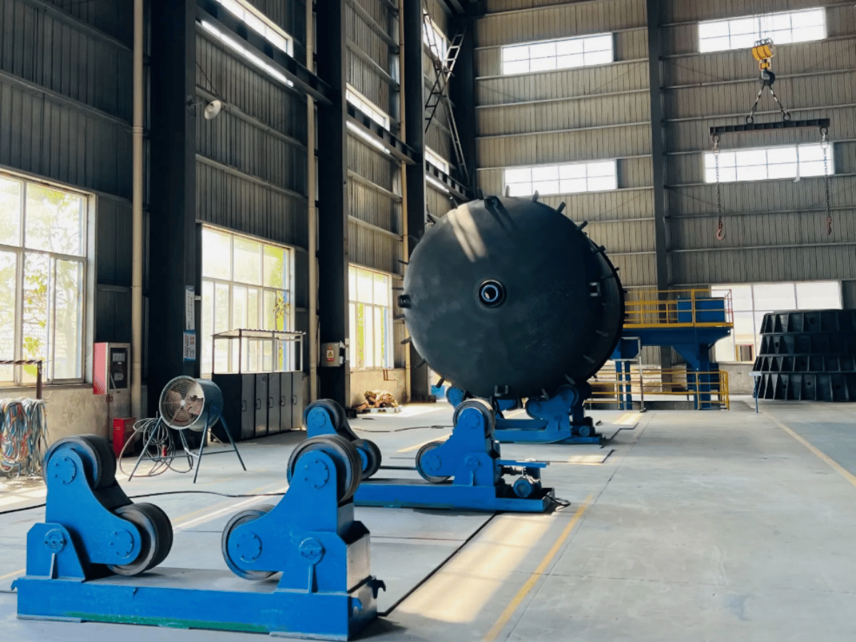
For large cylindrical sections, compare the beveling station with the handling and fit-up sequence in the wind-tower production line, so cut speed does not outrun rolling, positioning or transfer.
RESIZE’s public page lists portable and pipe-oriented beveling machines with pneumatic, electric and hydraulic power options. Its published angle and cutting-depth ranges are first-party family claims; ask which exact model and material support the quoted values.
Match the trial to the proposed architecture. Don’t accept a stationary-cell claim demonstrated with a hand-guided tool, or a portable-tool claim based only on a short coupon fixed at bench height. Use the actual orientation, practical edge length, proposed power supply, expected operator access and real handling route. Machine family is part of the test condition, not a label that can be swapped after the result is measured.
Heavy-Plate Sample-Run Acceptance Protocol
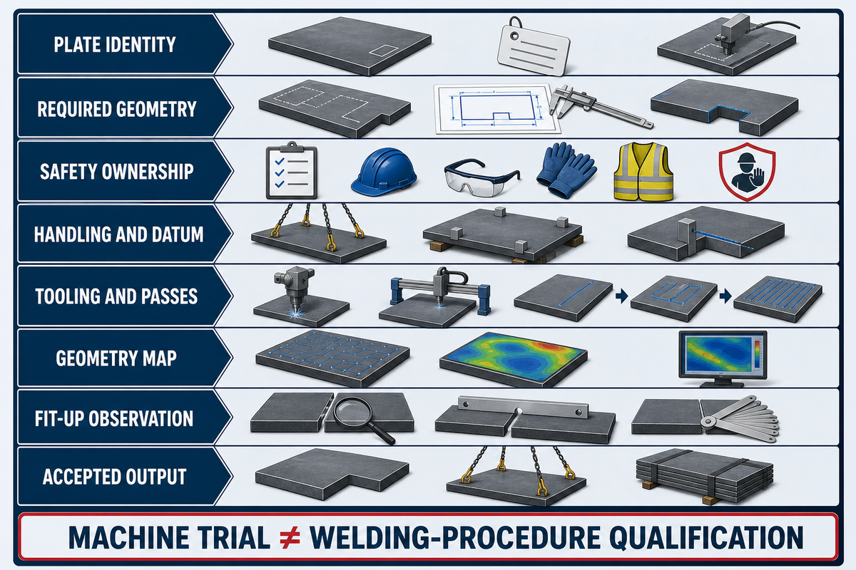
Representative sample runs can demonstrate bevel geometry, repeatability, handling behavior and observed accepted output on the buyer’s plate. They can’t by themselves qualify a welding procedure or certify the finished weld. Any architecture decision must therefore be verified through a representative plate trial, while downstream decisions retain their own controlled evidence and responsible parties.
Machine trial: edge geometry and production evidence. Welding-procedure qualification: joining-process evidence. Finished-weld acceptance: inspection evidence. Don’t collapse the three into one “weld-ready” checkbox.
| Trial field | Record | Acceptance source |
|---|---|---|
| Plate identity | Grade, heat/lot, thickness, condition, coating and edge state | Buyer material record |
| Required geometry | Angle, root face, depth, side and edge length | Controlled drawing / procedure |
| Safety ownership | Guarding review, exclusion area, chip control, intervention and energy-isolation responsibility | Employer procedure and machine instructions |
| Handling and datum | Lift/support method, clamps, re-clamps, datum checks and minutes | Trial plan |
| Tooling | Head/tool geometry, insert grade, edge/index position and starting condition | Supplier proposal |
| Machining strategy | Speed/feed settings, number of passes, direction and adjustment events | Quoted process plan |
| Tool and chip events | Stops, insert indexing/replacement, chip clearing and safe-service minutes | Observed record |
| Surface and burr state | Visible burr, chatter, tearing, oxidation or finish change | Buyer inspection plan |
| Geometry map | Buyer-defined points with actual angle, root face and depth readings | Drawing tolerance and quality plan |
| Fit-up observation | Alignment and preparation-related issues at the next operation | Fit-up plan; not finished-weld approval |
| Accepted output | Processed meters, rework meters, rejected meters and accepted meters with total elapsed time | Buyer trial acceptance record |
Run the protocol on the material and edge geometry that matter commercially. A thin demonstration coupon on clean material may prove that the spindle turns and the angle adjusts; it doesn’t prove the proposed system can handle a long, imperfect production plate or the required shift mix.
Close the trial with an evidence packet, not a verbal verdict. Include the controlled drawing revision, plate record, machine and tooling identity, setup photographs if permitted, measurement instrument IDs, the completed geometry map, all station times, interruption notes, rework disposition and the signatures or approvals required by the buyer. If the edge later enters a welding-procedure qualification or production weld, create a separate record for that activity. The beveling report should never claim that a successful edge trial qualified the joining process.
Even failed results are useful when the variables are preserved. State whether the failure was geometry, surface condition, handling stability, tool life, safety, time or downstream fit-up. Then change one controlled variable for the next attempt. Changing feed, insert, support and pass depth together may produce a good second edge, but it destroys the evidence needed to repeat the result.
Normalize RFQs Around Accepted Output
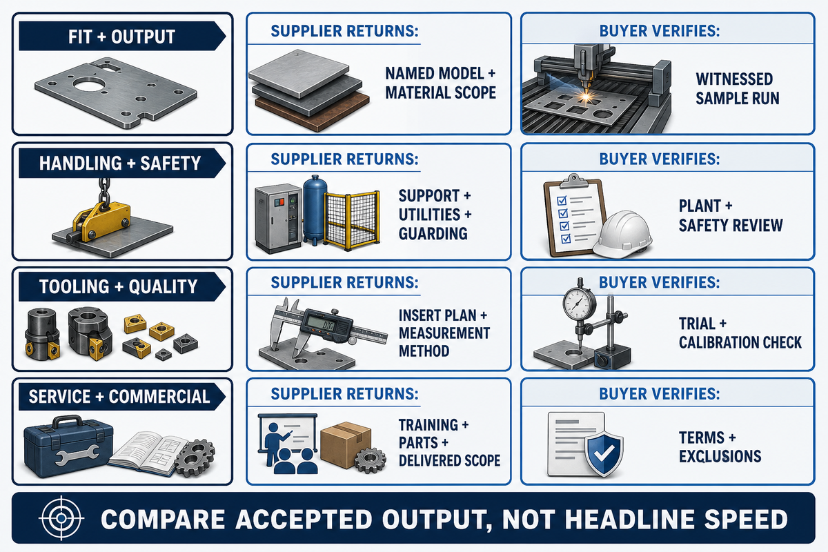
Comparable requests for quotation give every supplier the same workpiece, geometry, workload, handling, utility, safety and sample-acceptance scope. Accepted output is the normalization spine, but it isn’t the only purchasing axis. Delivery capacity, quality-system evidence, total cost, technical support, consumable availability and incoming verification must remain visible.
| Scorecard category | Supplier must return | Buyer verification |
|---|---|---|
| Plate and geometry fit | Named model, material scope, bevel range, pass plan and exclusions | Drawing-to-quotation check |
| Accepted output | Representative-run times, meters, rework and assumptions | Buyer-witnessed protocol |
| Handling and integration | Support, clamping, lifting, turnover, footprint, utilities and transfer needs | Plant layout and utility review |
| Safety boundary | Guarding features, operating zone, chips, servicing and isolation instructions | Competent safety assessment |
| Tooling and consumables | Insert grade, edges per insert, expected service method, included stock and lead time | Trial events and supply check |
| Quality evidence | Measurement method, calibration needs, trial report and deviation response | Quality-system review |
| Service and training | Commissioning scope, operator/maintenance training, response path and parts support | Service terms and references |
| Commercial and delivery | Price basis, exclusions, payment, production lead time, shipping and acceptance milestone | Total landed and installed scope |
This scorecard is a buyer-use framework, not an industry standard. The buyer owns the thresholds. If a weighted comparison is useful, define the weights before opening quotations and make them total 100%. For example, a plant may assign more weight to accepted output and geometry evidence than to purchase price, but another plant facing a shutdown may rank delivery and service first.
Use a simple calculation to keep the weighting visible: weighted contribution = supplier rating ÷ 5 × category weight. If sample evidence has a 25% weight and a supplier earns 4 out of 5, that category contributes 20 points. Repeat the calculation for every category and add the points. Issue the rating scale, evidence required for each rating and category weights with the RFQ; otherwise the score can be adjusted after prices are known and becomes a justification rather than a decision tool.
Keep commercial exclusions beside the score, not in a separate email chain. A low machine price may omit plate supports, special tooling, commissioning, training, inspection equipment, spare inserts, freight or installation work. Scorecard rows should identify who supplies each item and whether it’s required before the acceptance trial. That makes the comparison closer to total installed scope without pretending that public price pages describe equivalent configurations.
Searches for plate beveling machine price, plate beveling machine parts or plate beveling machine for sale rarely define an equivalent installed scope. Use those queries to identify suppliers, then return to the same geometry, handling, tooling, service and sample-acceptance fields before comparing price.
Why does bevel length belong in the RFQ?
Total edge length controls more than cutting time. It affects plate support, travel stability, insert exposure, inspection-point planning and the business value of self-feeding or stationary equipment. State meters and feet per plate, plates per shift and the mix of short and long edges; a single maximum length hides changeovers and queue behavior.
Build the Supplier Evidence Pack Before You Quote Capacity
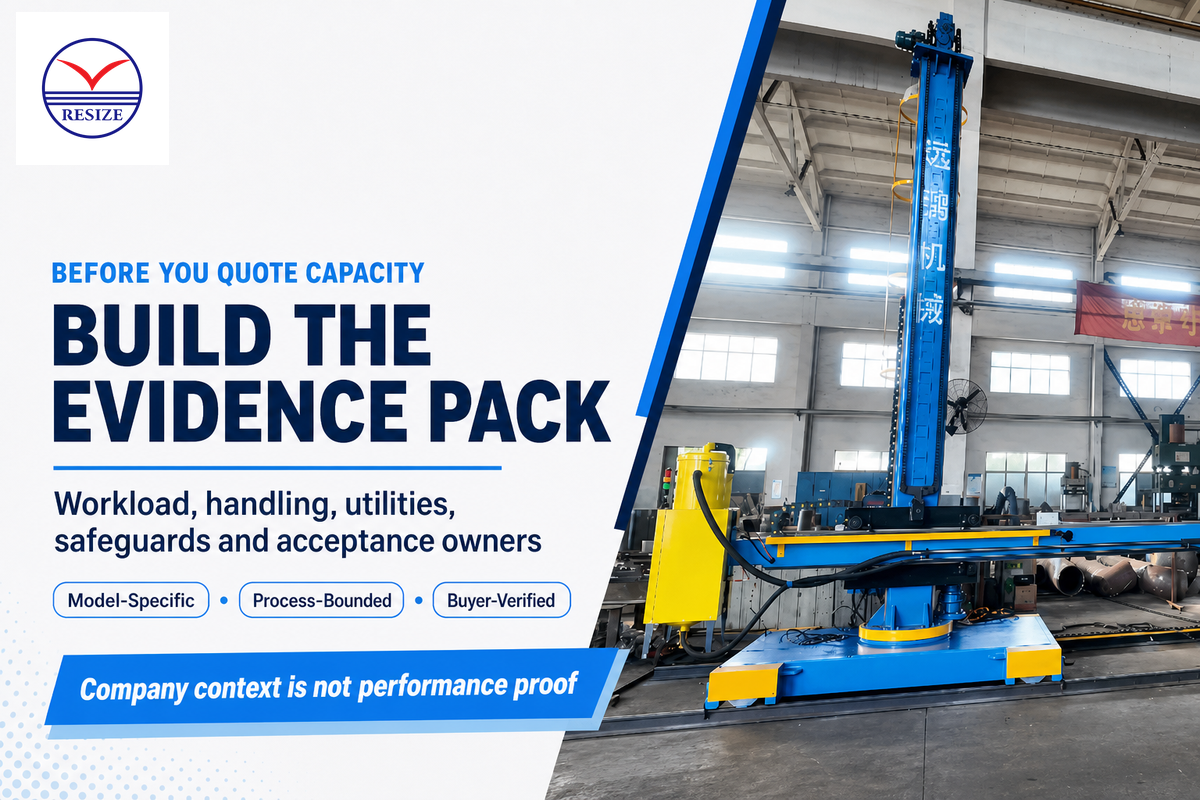
Capacity proof should follow the plate mix in the plant’s order and drawing pipeline, not public search demand or a generic market forecast. Put the controlled workload, handling constraints, utilities, guarding responsibilities, sample fields and acceptance owners in one evidence pack so each supplier quotes the same production problem.
Keep emerging-technology claims in a separate evidence row with their process boundaries. In 2025, a peer-reviewed study evaluated ultrasonic sensing and adaptive robotic plasma bevel cutting on plane steel plate. It supports asking how measured variables affect adaptive control under the proposed process, but it doesn’t establish the performance of a cold-milling beveling machine. Read the study and its stated process scope.
List every referenced standard with its date and scope rather than treating the latest year as a universal update. ISO 9692-1:2013 remains current after confirmation in 2023, while ISO 9692-2:2024 has a narrower submerged-arc-welding scope. A 2024 date is not evidence that every heavy-fabrication groove changed.
Next, send the representative plate grade and condition, drawing or controlled groove dimensions, total edge length and shift mix, one- or two-side access, handling path, available utilities, guarding expectations, sample-run fields and acceptance ownership. Use these fields when requesting a RESIZE quotation for a heavy-plate milling and beveling configuration.
RESIZE’s public page lists adjustable angles from 0–60° and a maximum cutting-depth claim of 0–25 mm. Treat both as first-party family-level information and confirm the proposed model, material and configuration in the quotation.
On its About page, Wuxi Yuanpeng Machinery Equipment Factory states that its Wuxi and Changzhou operations provide more than 4,000 square meters (about 43,000 sq ft) of production space. Treat that as first-party company context, not proof that a proposed model will meet this article’s trial or throughput requirements.
Часто задаваемые вопросы
How do you bevel a plate for welding in a heavy-fabrication line?
Start from the controlled drawing or welding procedure, then plan plate handling, machine setup, safe intervention, multi-point inspection and fit-up transfer as one production route with separate acceptance owners.
Identify the plate grade, thickness and edge condition, then take the groove angle, root face and depth from the controlled drawing or welding procedure. Establish support and datum, confirm guarding and intervention responsibilities, make a trial cut, and inspect at buyer-defined points along the edge. Record handling, setup, pass, tool-service, inspection and fit-up-transfer time before release. Machine trials prove preparation geometry and observed repeatability; they don’t replace welding-procedure qualification or final weld inspection. Link each failed point to its location, tool condition and setup state before another variable is changed.
What tool makes beveled edges on long heavy plate?
The suitable tool may be portable, self-feeding or stationary; choose among them from plate access, repeated edge length, handling capacity, required geometry and the evidence expected from a representative trial.
Portable tools suit access-led or intermittent work. Self-feeding machines suit recurring straight edges when the travel path can be held stable. Stationary edge milling suits scheduled plate flow when the plant can support loading, clamping, utilities and transfer. Compare all architectures with the same representative plate, controlled groove, handling route and acceptance protocol rather than a short demonstration coupon.
Is automation right for my plate-beveling application?
Automation is justified when repeated accepted output and labor release outweigh added handling, integration, guarding and maintenance duties, and when the whole seven-station route can support the proposed in-cut capacity.
Time all seven stations rather than the cutting pass alone. Include plate movement, supports and clamps, geometry setup, all machining passes, insert service, inspection, rework and downstream queues. Compare accepted meters and total elapsed time on more than one representative plate. If a self-feeding or stationary machine raises in-cut capacity but the plate waits at lifting or inspection, the investment has moved the constraint. Also check utilities, operating-zone safeguards, parts supply, training and the maintenance response required to keep the proposed rate available after commissioning.
When is a double-sided bevel worth the additional plate handling?
A double-sided bevel is worth considering when the reduction in groove volume exceeds the time, cost and risk of plate turnover, reverse-side access, datum recovery, second-side machining and inspection.
Calculate both groove areas from the controlled geometry, then add turnover, datum recovery, second-side machining, inspection and weld sequence. There’s no universal thickness where the answer changes. Test both routes when the decision carries material cost or schedule risk.
What should a heavy-plate sample run record before purchase?
Record plate identity and condition, the controlled groove, safety ownership, handling and datum time, tooling and passes, a multi-point geometry map, fit-up observations, rework, rejects and accepted output.
Include the plate grade, heat or lot, thickness, hardness or condition when relevant, coating and starting edge. Record supports, clamps, datum checks, setup time, machine and tool identity, insert grade and edge position, feed and speed settings, machining direction, pass count, adjustments, service events, chips, burr and surface observations. Map actual geometry at buyer-defined locations and retain instrument IDs. Close with processed meters, rework, rejects, accepted meters, fit-up observations and total elapsed time. State who approved each field. Keep welding-procedure qualification and finished-weld acceptance outside the machine-trial verdict; those require separate records and responsible reviewers.
Ссылки и источники
- 29 CFR 1910.212 — General Requirements for All Machines — Occupational Safety and Health Administration
- ISO 9692-1:2013 — Types of Joint Preparation for Steels Международная организация по стандартизации
- ISO 9692-2:2024 — Joint Preparation for Submerged Arc Welding of Steels Международная организация по стандартизации
- Calculating Weld Volume and Weight — TWI, Gene Mathers
- Design Part 4: Joint Preparation and Fit-Up — TWI, Gene Mathers
- 5 Steps for Proper Weld Preparation — The Fabricator, Rick Hopkins
- Ultrasonic-Driven Adaptive Control of Robotic Plasma Arc Cutting for Bevel Applications — The International Journal of Advanced Manufacturing Technology
Why this guide uses a trial-first method
RESIZE publishes milling and beveling equipment information, but public pages can’t describe every buyer’s plate mix, handling route or acceptance plan. This article therefore separates published family claims from buyer-supplied evidence and turns the research into worksheets that can be checked during a representative heavy-plate trial.