Updated August 2026
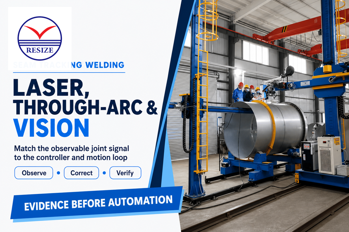
Seam tracking welding is in-process correction of a programmed path during welding. Select a system by evidence: can the joint produce a usable signal, can the controller turn it into stable motion, and can the complete loop pass a representative production test?
Laser and camera systems observe joint geometry; through-arc systems infer position from the welding process. Choose by observable joint features, process stability, access, controller integration, and evidence from a representative test, not by sensor category alone.
- Seam finding, in-process tracking, weld-pool monitoring, and post-weld inspection are different jobs.
- A precise sensor can still fail if calibration, coordinates, latency, motion authority, or the process signal is wrong.
- Laser profile, passive camera, through-arc, and tactile sensing overlap in application; none is a universal winner.
- Commission with buyer-defined thresholds on representative joints and keep the resulting configuration and quality evidence.
Quick Specs: define these before asking for a tracker
| Joint and weld | Joint type, groove preparation, material, thickness, pass, process, wire, and position |
| Variation to correct | Measured lateral, height, orientation, gap, and fit-up envelope from the buyer’s parts |
| Observable input | Visible joint profile, stable arc signal, tactile edge, or another documented feature |
| Integration | Sensor output, controller interface, coordinate frames, correction authority, alarms, and recovery |
| Acceptance evidence | Calibration record, representative coupon, logged correction, finished-weld result, and decision owner |
What Seam Tracking Corrects, and What It Does Not
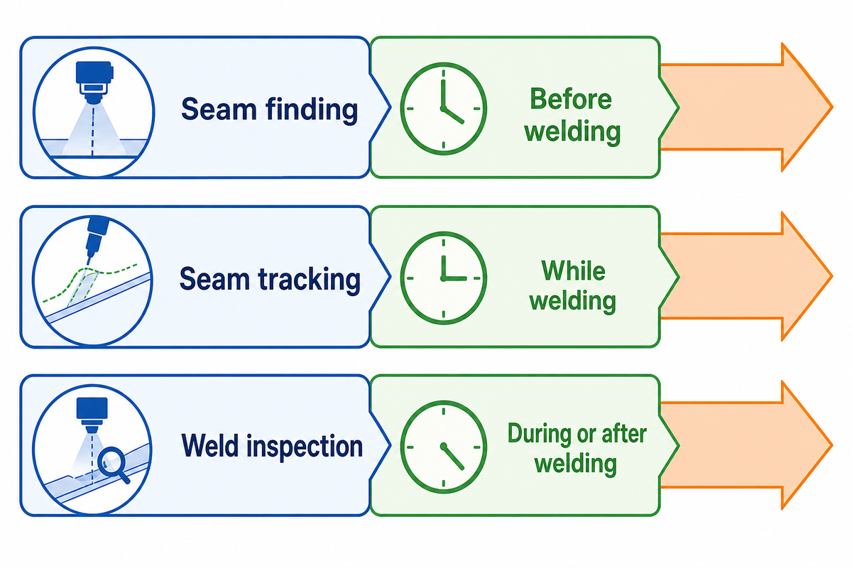
Welding seam tracking is in-process path correction. A sensing system estimates the location of the actual joint, a controller converts that estimate into the machine coordinate system, and controlled motion adjusts the torch or workpiece within a qualified correction envelope.
Programmed paths represent where joints were expected to be. Production parts may differ because of forming, fixturing, tack placement, thermal distortion, or accumulated dimensional variation. Tracking can respond to the part that’s present, but only when the joint creates a usable observation and the rest of the control loop is able to act on it.
This peer-reviewed review of robotic welding sensing describes a broader sensing landscape that includes seam location, tracking, weld-pool observation, and quality monitoring. That breadth makes one distinction essential: when the observation occurs and what the controller does with it are separate questions.
| Функция | When it operates | Useful output | What it does not prove |
|---|---|---|---|
| Seam finding | Before welding or before a segment | Start-point or path registration | Continuous correction during the weld |
| Seam tracking | While the weld is being made | Path correction commands | Finished-weld acceptance |
| Weld inspection | During or after welding | Recorded condition or quality indication | That the torch followed the intended joint |
Some systems perform more than one function. That does not erase the boundaries. Quotations and acceptance plans should state which output commands motion, which output is informational, and which separate method accepts the finished weld.
The Correction Loop Behind Every Tracking System
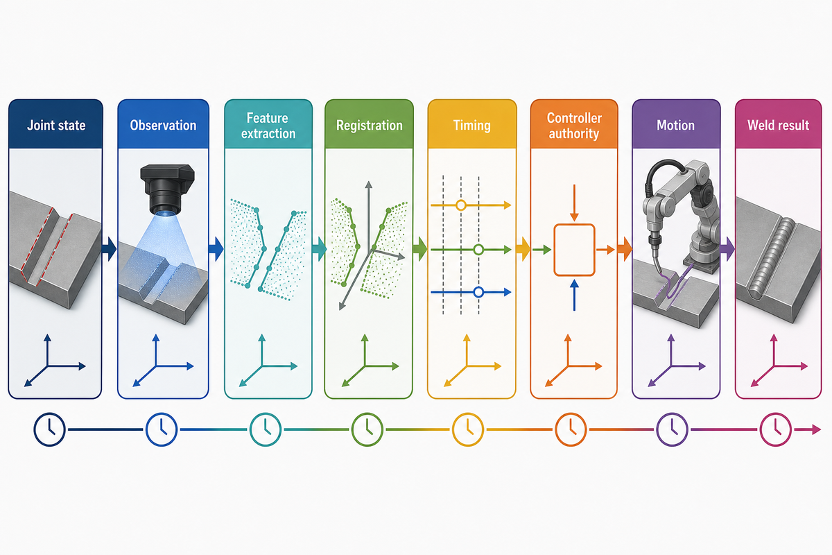
The tracker is a measurement-and-control chain, not just a sensor. Joint variation must be observed, transformed into the correct coordinates, filtered, delivered to the motion controller, executed within allowed limits, and checked against the weld result.
The Sensor-to-Torch Offset Stack exposes the parts of that chain that a sensor brochure can hide. Start with the real joint variation. Each sensor converts an observable feature into a position estimate or an error signal. Calibration and registration relate the sensor frame to the torch, robot, carriage, or workpiece frame. Filtering handles noise; the controller accounts for timing and decides which axes may change. Its motion system executes that decision, while the weld process continues to create heat, arc light, spatter, and distortion.
NIST’s calibration and registration work is a useful vocabulary check. Accuracy concerns closeness to a reference; repeatability concerns the spread when a condition is repeated; registration concerns the relationship between coordinate systems. A repeatable measurement in the wrong transform can still drive the torch to the wrong place. A catalog accuracy number does not close registration, timing, or motion error.
| Layer | Question to answer | Evidence to retain |
|---|---|---|
| Joint state | What variation actually occurs? | Measured production-part envelope |
| Observation | Which physical feature or process signal is usable? | Raw image, profile, current, voltage, or contact record |
| Feature extraction | How is the tracking point calculated? | Recipe and software/configuration version |
| Registration | How is sensor data related to the tool and workpiece? | Calibration result and frame definitions |
| Timing | Where was the joint when the correction is applied? | Sampling, filtering, offset, and latency settings |
| Controller authority | Which axes and limits may be corrected? | Interface map and limit configuration |
| Движение | Can the machine execute the requested change? | Commanded versus actual path |
| Weld result | Did the qualified weld meet its acceptance method? | Inspection result linked to the run |
One common commissioning mistake is to move the sensor until one coupon looks right, then preserve no transform or configuration record. Such an apparent fix can’t be reproduced after a torch change, sensor service, software update, or fixture move. This complete stack should have a baseline and a defined recheck trigger before it can automate a real-time response at the planned travel speed.
How Laser Profile and Vision Systems Observe Joint Geometry
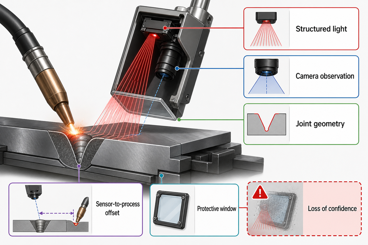
Laser profile trackers project structured light onto the workpiece and use a camera to calculate joint geometry. Other camera systems may use passive or separate illumination. Their advantage is direct geometric observation; their limitation is that the required feature must remain visible and correctly related to the torch.
TWI’s laser-welding seam-tracking guidance explains both pre-process sensing and in-process approaches. A sensor mounted ahead of the process can observe a cleaner joint, but it creates a physical sensor-to-process offset. Tight curves, corners, and orientation changes can make that look-ahead relationship difficult. Sensing near the process reduces the look-ahead problem but places the optical system closer to intense process emissions.
Laser lines do not create magic contrast. An algorithm still has to isolate a usable joint feature from surface reflectivity, preparation marks, tack welds, variable edges, arc light, smoke, and spatter. Protective windows and optical paths can become maintenance variables. These constraints apply to optical sensing; they should not be copied wholesale into a through-arc limitation list.
Procurement should therefore ask a specific question: which joint feature is extracted, under which surface and process condition, at what sensing location, and how is loss of confidence reported? Request sample images or profiles from representative parts. Include the least convenient orientation, expected tack pattern, surface range, start/stop area, and an intentionally difficult but production-realistic condition.
One 2021 experimental study reported tracking-error reductions of up to 38.38% and 41.71% for two directions in its particular robotic GMAW method and test setup. Those figures show that a defined laser-vision signal-processing method can be measured; they aren’t performance promises for another sensor, joint, or production cell.
- Expose the actual surface range.
- Test curves, corners, and tacks.
- Record confidence loss and recovery.
- Preserve sensor-to-tool calibration.
- Generalize one bench accuracy value.
- Assume every camera uses a laser profile.
- Hide the worst optical condition.
- Treat a clean coupon as the production envelope.
When a supplier says “vision,” ask for the sensing modality and the operational job. One camera family may support seam finding, in-process tracking, weld-pool observation, or inspection, yet the configuration, timing, protective hardware, and controller connection can be different.
How Through-Arc Seam Tracking Reads the Welding Process
Through-arc seam tracking uses changes in welding-process signals to infer the torch’s relationship to the joint. It can avoid a separate optical view of the seam, but it depends on a stable, informative process signal and a compatible controller, joint, and motion pattern.
That peer-reviewed sensing review describes arc-signal approaches alongside visual, acoustic, and other methods. In a common through-arc arrangement, the torch samples different sides of the joint during a controlled weave. Differences in current or voltage behavior are processed into lateral and, where supported, height corrections. Arc behavior and wire position become part of the measurement chain.
That is why “no external sensor” should not be read as “no sensing constraints.” Wire extension, contact-tip condition, arc length control, transfer behavior, joint geometry, weave pattern, travel condition, welding parameters, power-source communication, and electrical noise can all affect the available signal. A stable weld process is not merely the output; it is also part of the input.
Do I Need to Use Weaving When Running TAST Seam Tracking?
Often, a through-arc algorithm needs a repeatable comparison across the joint, and weaving is a common way to create it. Blanket answers are not always appropriate. An applicable controller manual and application test must show how its algorithm obtains a lateral or height signal. If a vendor supports a different sampling pattern or limited straight-travel function, record that system-specific condition rather than calling it universal TAST behavior.
What Joint Types and Thicknesses Are Suitable for TAST?
No responsible answer starts with a universal thickness range. First ask whether the joint presents enough process-signal difference across the planned motion, whether the required weave and heat input are compatible with the welding procedure, and whether the controller supports the joint and welding mode. Groove and fillet applications are common candidates, but “common” is not an acceptance result. Prove the exact material, joint preparation, pass, position, process window, travel direction, and expected fit-up on representative coupons.
Ask to see the raw or processed signal during an induced joint deviation, the algorithm’s confidence or alarm behavior, the allowed correction axes, and what happens when the arc becomes unstable. If the system keeps sending corrections when its input is no longer trustworthy, the missing feature is not a better accuracy claim—it is a controlled failure state.
Separate Sensing Modality From the Job It Performs
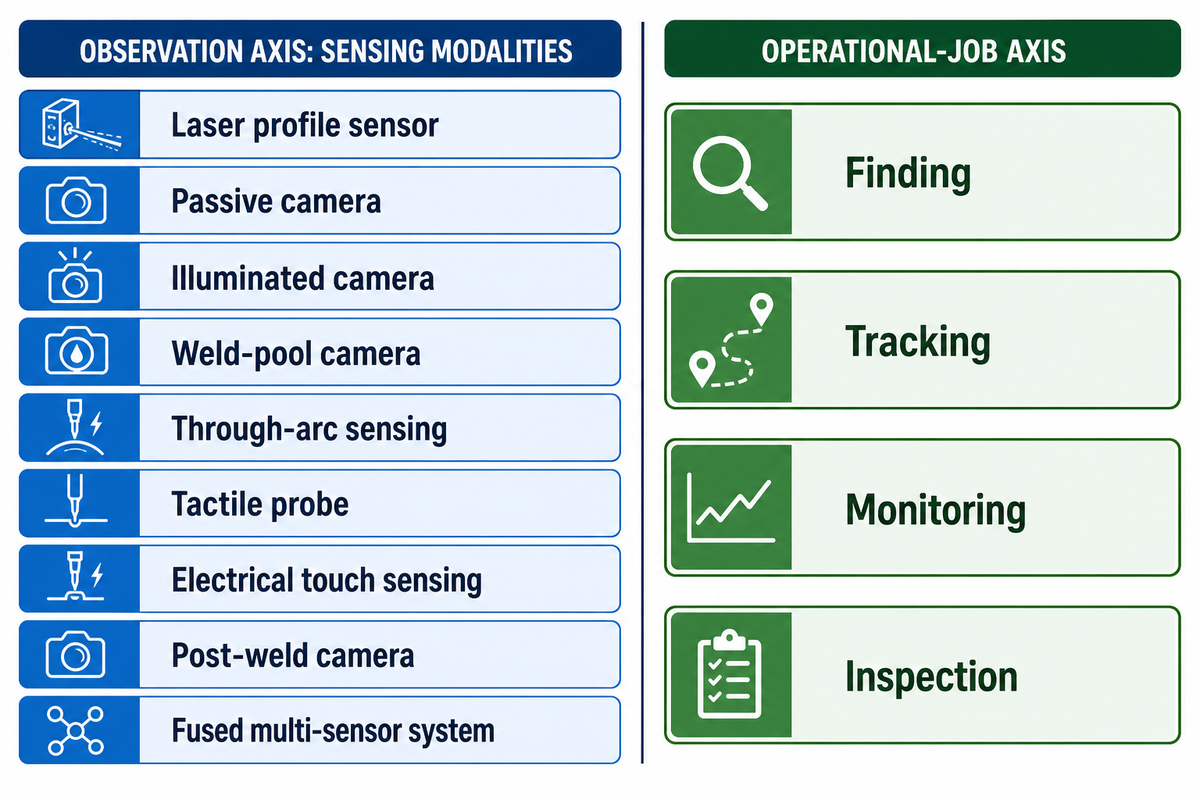
A sensing modality describes what creates the observation; an operational job describes what the system does with that observation. The peer-reviewed sensing review supports this separation: laser profile, passive camera, through-arc, and tactile sensing belong on one axis, while finding, tracking, monitoring, and inspection belong on another.
This two-axis model prevents a false comparison such as “vision versus tracking.” Vision can be used for tracking. It also prevents the opposite mistake: assuming every product called a vision system closes the loop and commands motion.
| System description | Primary observation | Possible assigned job | Limitations / not suitable for |
|---|---|---|---|
| Laser profile sensor | Structured-light joint profile | Finding or in-process tracking | Unproven when the required profile is obscured |
| Passive camera | Scene or process image | Finding, tracking, or monitoring | Needs usable illumination and image features |
| Illuminated camera | Controlled-light image | Finding or tracking | Lighting and surface condition remain part of the test |
| Weld-pool camera | Pool, arc, or nearby process scene | Monitoring; sometimes control | Observation alone does not prove path correction |
| Through-arc sensing | Welding-process signal | In-process tracking | Needs a stable, informative signal and supported process |
| Tactile probe | Physical contact with an edge | Finding or guided tracking | Access, contact wear, and cycle interaction must be tested |
| Electrical touch sensing | Contact event using conductive hardware | Pre-weld finding | A found start point is not continuous tracking |
| Post-weld camera | Finished surface appearance | Inspection or documentation | Does not establish subsurface quality or tracking history |
| Fused multi-sensor system | Two or more synchronized inputs | Tracking, monitoring, or adaptive control | Adds calibration, timing, and failure-mode obligations |
On a quotation, replace “vision included” with four fields: modality, observed feature, timing, and output. That small change tells engineering and procurement whether two bids are actually comparable.
Use the 9-Row Joint-Signal Fit Board to Shortlist a System
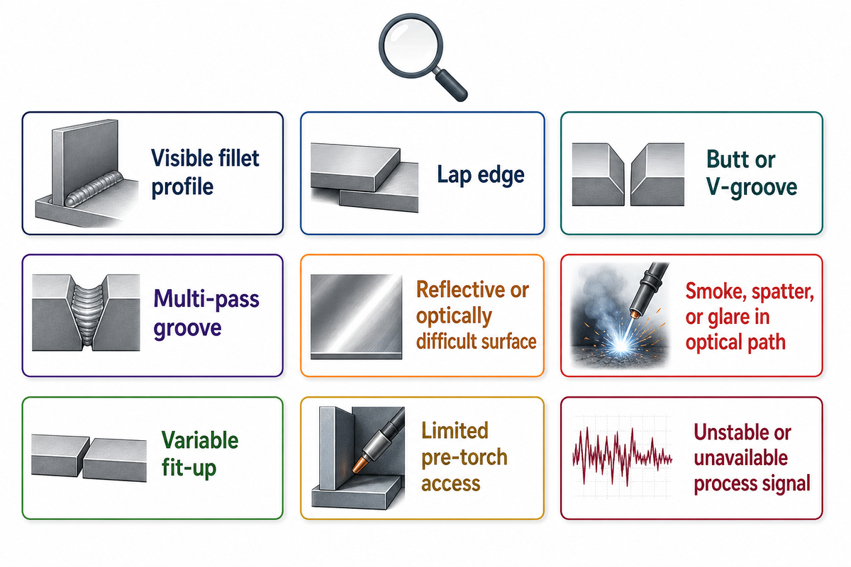
The Joint-Signal Fit Board starts from what the application makes observable. It turns nine recurring joint conditions into a technology shortlist, a disqualifying representative-coupon test, and evidence to retain. Every row remains conditional until that test is passed.
Fill the 9-Row Joint-Signal Fit Board with production evidence before a demonstration. Its source categories follow the peer-reviewed sensing review, while the board itself is a buyer framework rather than a published standard. Its candidate column is not a ranking. It identifies a first test based on a visible feature, process signal, or accessible edge. A supplier may propose another method, but should explain what it observes and how a failed observation is reported.
| Application condition | Observable feature or signal | Candidate shortlist | Disqualifying coupon test | Evidence to retain | Limitations / not suitable for |
|---|---|---|---|---|---|
| Visible fillet profile | Toe lines or profile; possibly arc response | Laser profile; camera; TAST if qualified | Worst orientation and tack pattern loses the required feature | Raw observation, tracking point, correction log | Needs application test; geometry alone does not choose a winner |
| Lap edge | Visible step or accessible edge | Laser profile; camera; tactile | Minimum production-real edge becomes ambiguous | Edge image/profile and rejected cases | Needs application test; edge condition may vary |
| Butt or V-groove | Groove edges/profile or qualified arc signal | Laser profile; camera; TAST | Expected fit-up state produces no stable center estimate | Fit-up measurements and run data | Needs application test; do not assume one pass represents all passes |
| Multi-pass groove | Prepared groove, prior bead, or process response | Optical or TAST by pass-specific test | A later pass cannot identify the selected tracking feature | Pass number, recipe, feature, transform | Needs application test; the observable feature changes by pass |
| Reflective or optically difficult surface | Qualified profile/image or process signal | Optical after exposure test; TAST if compatible | Production surface causes unstable or false feature extraction | Images/profiles across surface range | Needs application test; “reflective” alone does not reject all optics |
| Smoke, spatter, or glare in optical path | Protected optical view or arc signal | Repositioned/protected optics; TAST if qualified | Realistic exposure removes the feature or contaminates protection | Exposure duration, cleaning state, confidence log | Needs application test; optical limit is not automatically a TAST limit |
| Variable fit-up | Measurable profile plus qualified correction or parameter input | Geometry-sensing system; fused system | Fit-up leaves the tested observation or welding-procedure envelope | Measured variation, correction, process response | Needs application test; path correction does not fix every fit-up problem |
| Limited pre-torch access | Near-process image, arc signal, or contact feature | Compact optics; TAST; tactile by sequence | Sensor collides, loses view, or creates unusable look-ahead on the path | Envelope model and full-path dry run | Needs application test; mechanical access can eliminate a sound sensor |
| Unstable or unavailable process signal | Visible geometry or accessible edge | Laser profile; camera; tactile | Optical/contact alternative also fails under the actual condition | Signal stability and alternative-sensor record | Needs application test; not a reason to accept optics without proof |
Keep the shortlist to two primary candidates and one documented reason each could fail. That focuses the demonstration and protects procurement from comparing a proven configuration with an undefined promise.
Translate Sales Language Into Acceptance Evidence
Vendor vocabulary is useful only when it maps to a test. Use this compact translation board to keep tracking and weld acceptance evidence separate.
| Language in the brief | Evidence to request |
|---|---|
| Joint and workpiece | State the seam type, material thickness, workpiece, actual seam, and fit-up. Name butt joints, lap joints, fillet welds, or any complex seam geometry. |
| Process signal | Record the current welding process, welding techniques, welding power source and other power sources, welding torch, wire feed, arc characteristics, weld bead, and weld bead formation within the welder-approved window. |
| Automation path | For automated welding, welding robots, or production lines, document the taught path, seam path, tracking point, data to the robot, correct position, permitted torch movement, and high-speed condition. Do not equate fully automatic operation with repeatable results. |
| Sensing claim | Ask how the seam tracker or proposed seam tracking solutions track the seam, perform joint tracking or real-time tracking, measure the distance, and compensate. Test sensing solutions on highly reflective parts; reject unsupported advanced systems, high precision, micrometer, or precise seam claims. |
| Commercial claim | For fabrication or shipbuilding, translate welding technology, automation, easy integration, easy programming, pre-configured, industrially proven, and return on investment language into buyer-owned acceptance criteria. |
Integrate Tracking With the Robot, Controller, or Manipulator
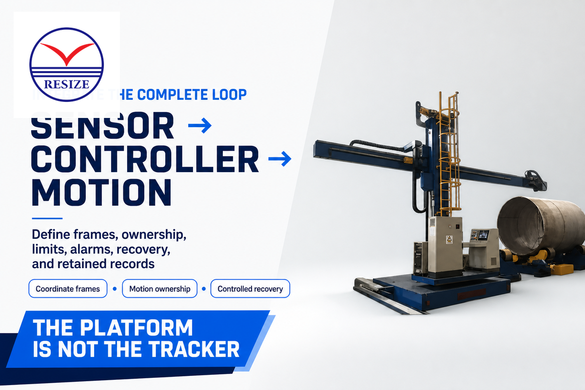
After a sensor locates the joint, the project still needs coordinate frames, a controller interface, defined motion ownership, correction limits, alarms, recovery states, and retained data. Controlled motion and seam tracking are separate configured layers.
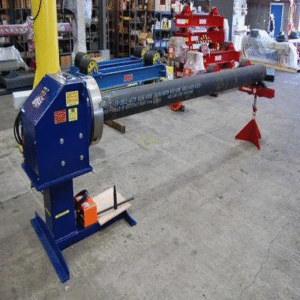
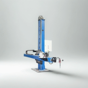
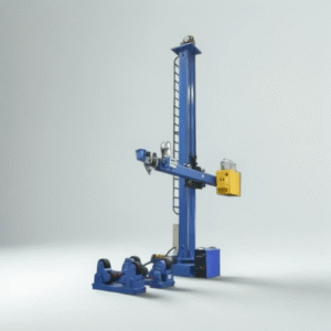
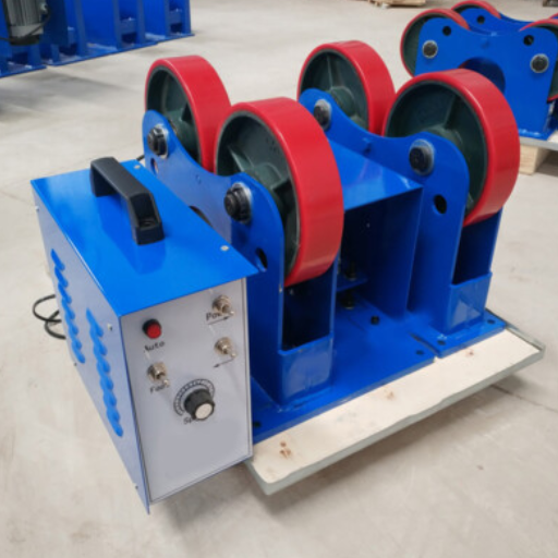
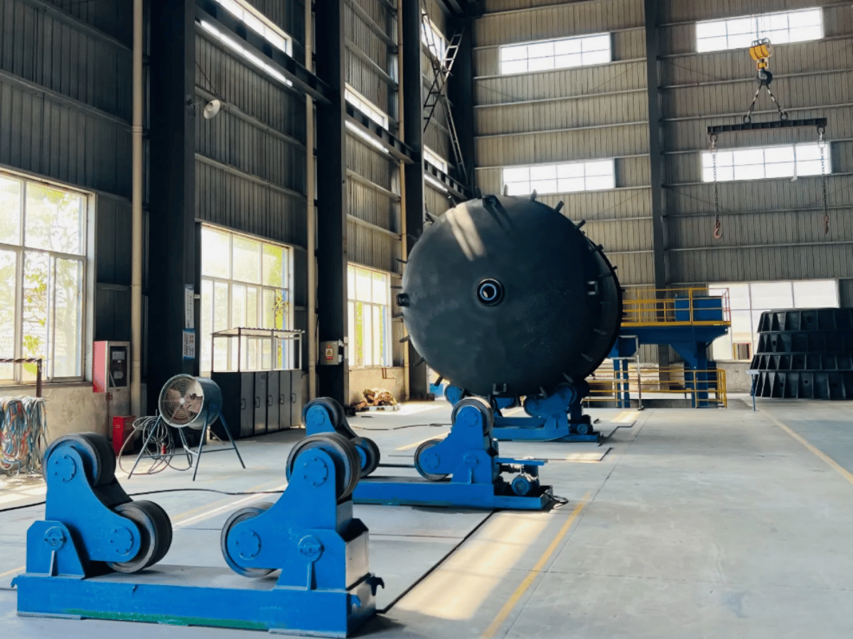
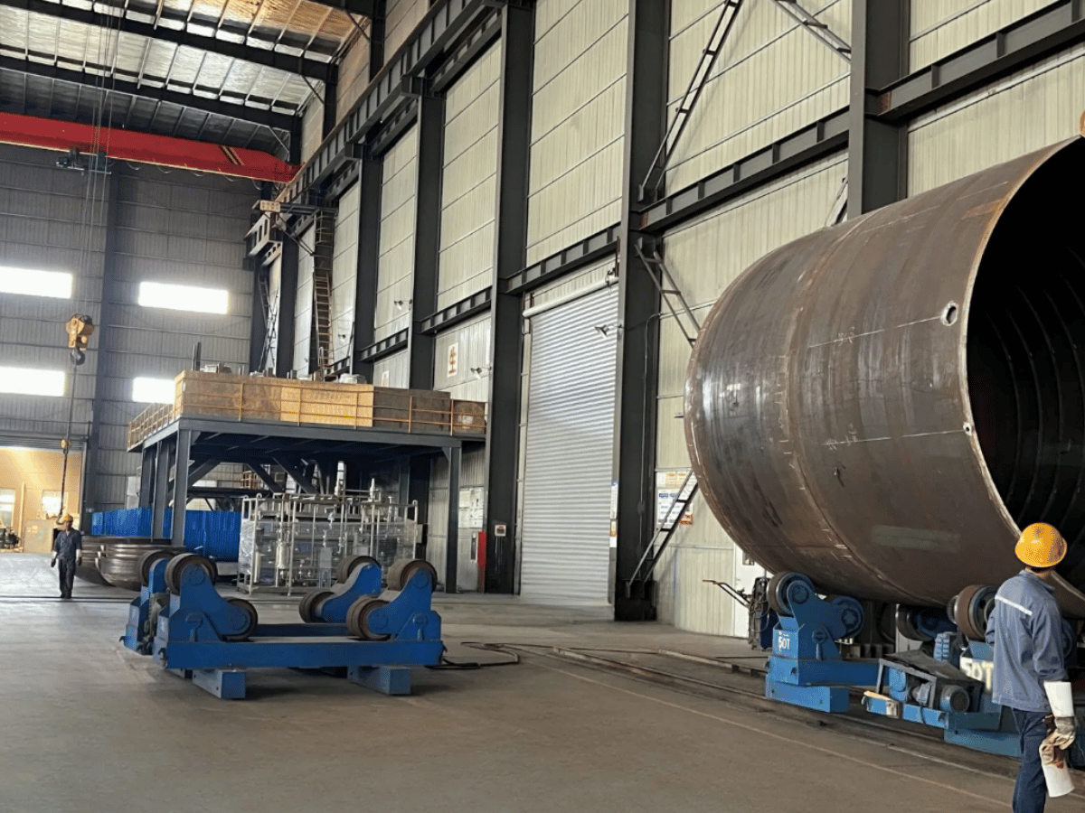
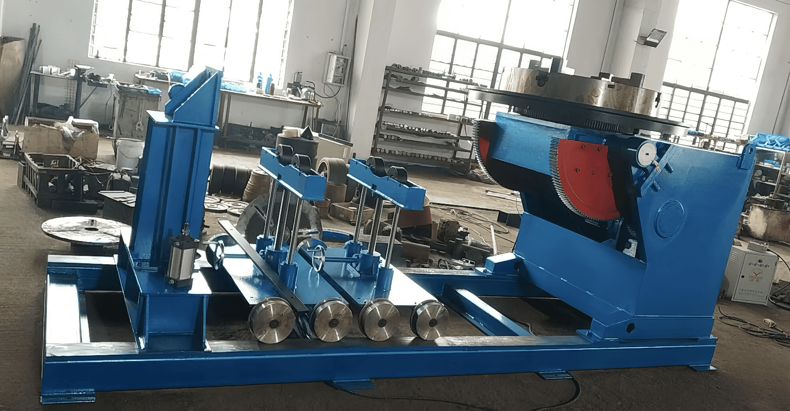
A robot may carry the torch, a carriage may move it along a beam, or a positioner may move the workpiece. An integration brief should say which controller receives the observation, which device owns each axis, and how simultaneous motions are coordinated. For long or circumferential work, a сварочный манипулятор can provide controlled positioning, but that doesn’t mean every manipulator includes a tracker, vision package, robot controller, or through-arc function. Project configuration must name them.
| Handoff | Define | Verify |
|---|---|---|
| Sensor to tracking controller | Data, quality/confidence, timing | Known input and lost-signal case |
| Frames and transforms | Sensor, tool, machine, workpiece | Calibration check at defined locations |
| Correction command | Axes, sign, rate, limits, enable state | Induced deviations in each allowed direction |
| Motion ownership | Robot, carriage, manipulator, positioner | Coordinated path and stop behavior |
| Alarm and recovery | Loss of signal, limit reached, restart owner | Fault injection and controlled recovery |
| Retained record | Configuration, correction, alarm, result | Run identity and retrievable evidence |
OSHA’s industrial robot guidance warns that erroneous inputs from peripheral equipment can lead to unpredicted robot operation.
That supports an integration warning, not a claim that tracking is a safety function. Safety-rated limits, protective devices, stop functions, risk assessment, and authorized recovery remain separate from the quality correction loop.
Commission the Complete Loop With a Proof Pack
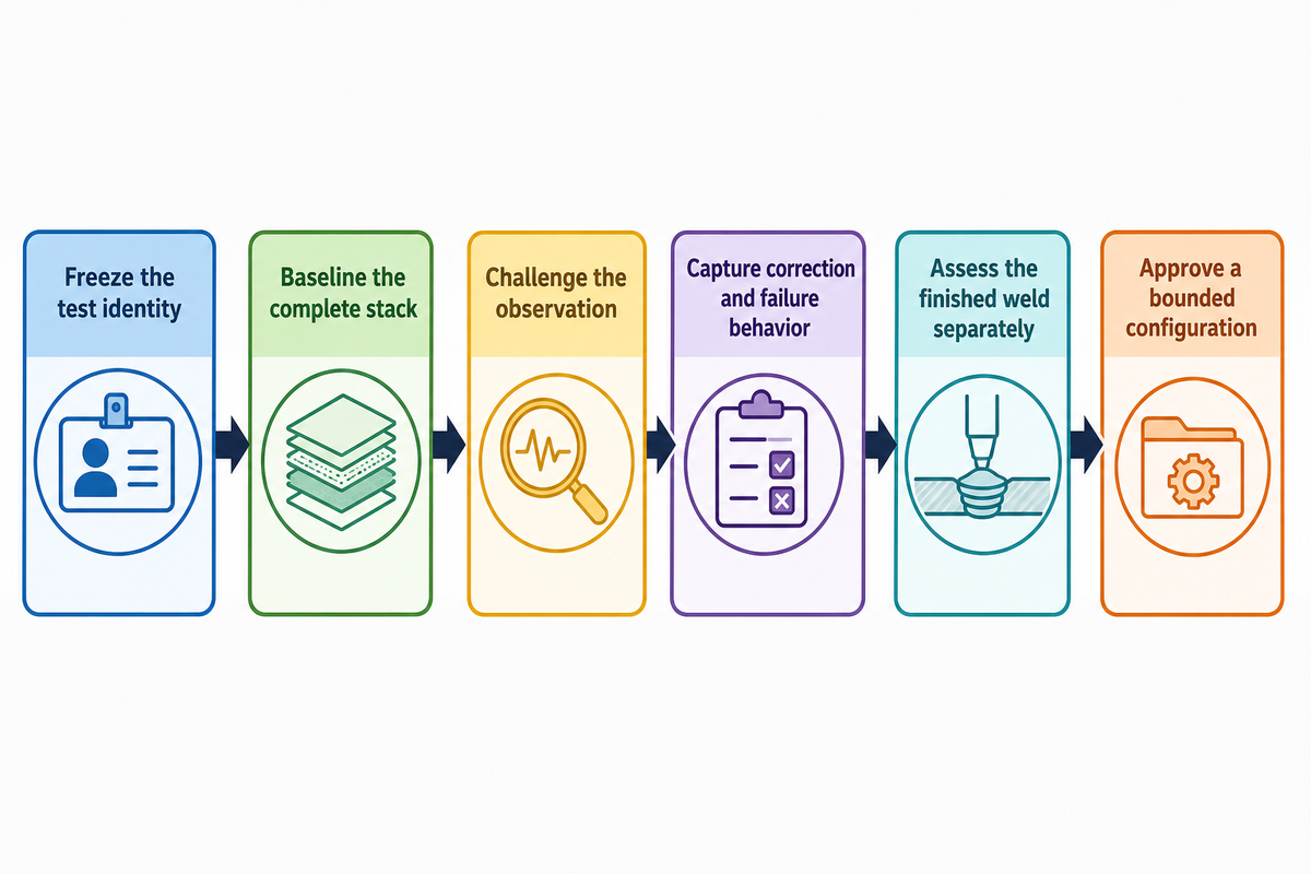
The Commissioning Proof Pack links a representative joint, welding condition, tracker configuration, calibration, commanded and actual motion, alarms, and finished-weld result. It turns a demonstration into evidence the buyer can reproduce after a controlled change.
- Freeze the test identity — record the joint, material, preparation, fit-up, position, pass, surface, fixture, and welding procedure condition.
- Baseline the complete stack — save sensor, software, recipe, coordinate frames, calibration, controller interface, limits, and motion configuration.
- Challenge the observation — include buyer-selected production variation and an expected weak condition without leaving the qualified welding or safety boundary.
- Capture correction and failure behavior — retain observations, commands, actual motion, confidence, alarms, and recovery decisions.
- Assess the finished weld separately — apply the project’s defined inspection and acceptance method; do not infer quality from tracking data alone.
- Approve a bounded configuration — identify the pass condition, decision owner, controlled range, and changes that require revalidation.
Keep four evidence scopes separate. ISO 17662:2025 addresses calibration, verification, and validation of equipment used for controlling process variables in welding and allied processes. Where applicable, ISO 15613:2025 covers qualification based on a pre-production welding test, while ISO 5817:2023 establishes quality levels for specified fusion-weld imperfections. ISO 10218-2:2025 covers industrial robot applications and cells across integration and their lifecycle.
These scope references do not select a laser, camera, tactile probe, or TAST package. Nor does one passing coupon prove equipment calibration, procedure qualification, every finished production weld, and robot-cell safety at once. Assign an owner and record to each lane.
Consider a hypothetical comparison. Test A uses a clean, straight coupon with a visible joint profile and current calibration. Test B uses the same sensor on a curved assembly with tacks, a changed bracket, and longer look-ahead. Passing Test A does not transfer automatically: observation, registration, geometry, and timing changed. Re-establish those records and assess the finished weld; do not invent a generic correction allowance.
Approve a seam-tracking configuration only for the joint, process, observation, calibration, controller, motion, and acceptance conditions that were actually tested—and define which changes reopen the evidence.
The Trend Is Sensor Fusion, the Buying Test Is Still Evidence
Newer seam-tracking research combines richer images, process signals, models, or multiple sensors to improve observability. That can expand what a system detects, but it also adds coordinate, timing, training-data, configuration, and failure-mode questions.
Recent work in Scientific Reports и Welding in the World illustrates the active development of visual recognition, sensing, and adaptive tracking methods. For procurement, the lesson is modest: better algorithms may make a previously weak feature usable under a studied condition. They do not remove the need to test the buyer’s joint or to control the path from sensing to motion.
For a fused system, ask what happens when inputs disagree, one sensor loses confidence, a model sees an out-of-distribution surface, synchronization drifts, or software changes. Retain both the combined output and enough underlying evidence to diagnose the result. Sophisticated sensing should make the proof pack richer, not optional.
Часто задаваемые вопросы
What is seam tracking in welding?
Answer
Seam tracking is the in-process correction of a welding path when the actual joint differs from the programmed path. A sensor or weld-process signal estimates position, the controller transforms it into machine coordinates, and the motion system adjusts the torch or workpiece within a tested range. It is different from finding a start point or inspecting the finished weld.
What is through-arc seam tracking?
Answer
Through-arc seam tracking infers joint position from welding-process signals as the torch samples the joint. Its usable information depends on joint geometry, motion pattern, arc stability, welding parameters, power-source communication, and controller logic. Verify supported processes, passes, positions, and failure behavior on representative joints; don’t treat it as a universal option.
What sensor makes sense for a welding application?
Answer
Start with what the application makes observable: joint profile, edge, process signal, or contact feature. Add the expected variation, surface, access, arc environment, travel condition, and controller interfaces. Shortlist at most two methods, define a coupon condition that would disqualify each one, and retain the raw observation, correction record, and finished-weld result.
Does through-arc seam tracking require weaving?
Answer
Many TAST algorithms use weaving, but the requirement is controller-specific. Confirm the sampling pattern, process, and joint in documentation and testing.
Is a vision system the same as laser seam tracking?
Answer
No. Laser profile sensing is one optical method. Camera systems can use other illumination and may perform finding, tracking, monitoring, or inspection.
When should seam tracking not be specified?
Answer
Don’t specify it as a cure-all when the joint offers no stable observable feature, the welding process can’t supply a qualified signal, access prevents safe installation, the controller can’t accept bounded corrections, or the production variation is outside the welding and motion envelope. Fixing the upstream joint or process may be the better action.
Related Resize reading: compare a pipe welding manipulator, a 3-axis welding positioner, and foundational weld positioners. For drawing terminology rather than path correction, see the separate guide to the seam weld symbol.
Ссылки и источники
- TWI: Can I use seam tracking systems for laser welding?
- Peer-reviewed robotic welding seam-tracking study (2021)
- Review of sensing technologies for robotic welding (2023)
- Scientific Reports seam-recognition research (2025)
- Welding in the World tracking research (2024)
- ISO 17662:2025, Calibration, verification and validation of equipment used for welding
- ISO 10218-1:2025, Industrial robots, Part 1
- ISO 10218-2:2025, Industrial robot applications and robot cells
- ISO 15613:2025, Qualification based on a pre-production welding test
- ISO 5817:2023, Quality levels for fusion-weld imperfections
- OSHA Technical Manual: Industrial Robots and Robot System Safety
- NIST: Calibration and Registration Tools