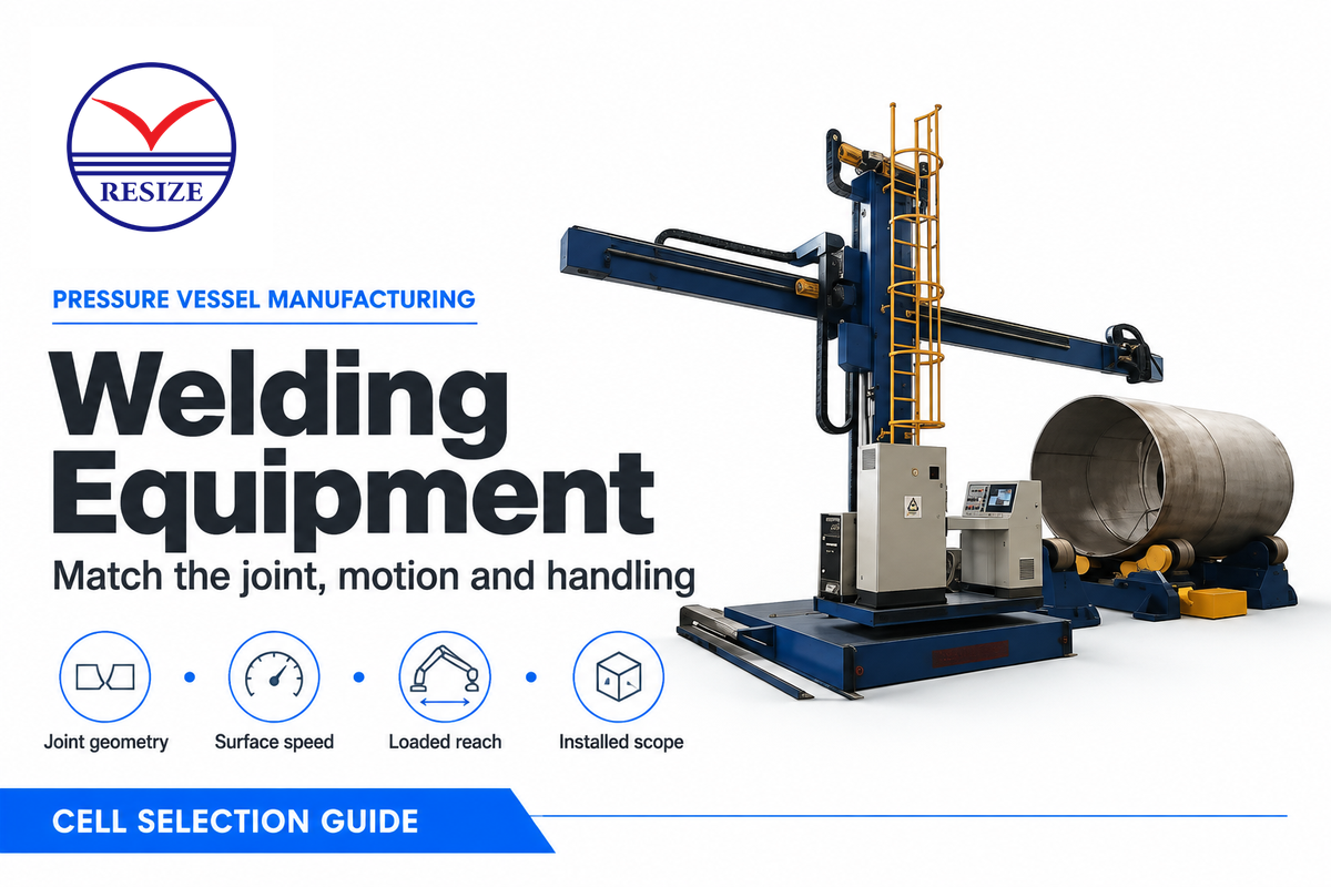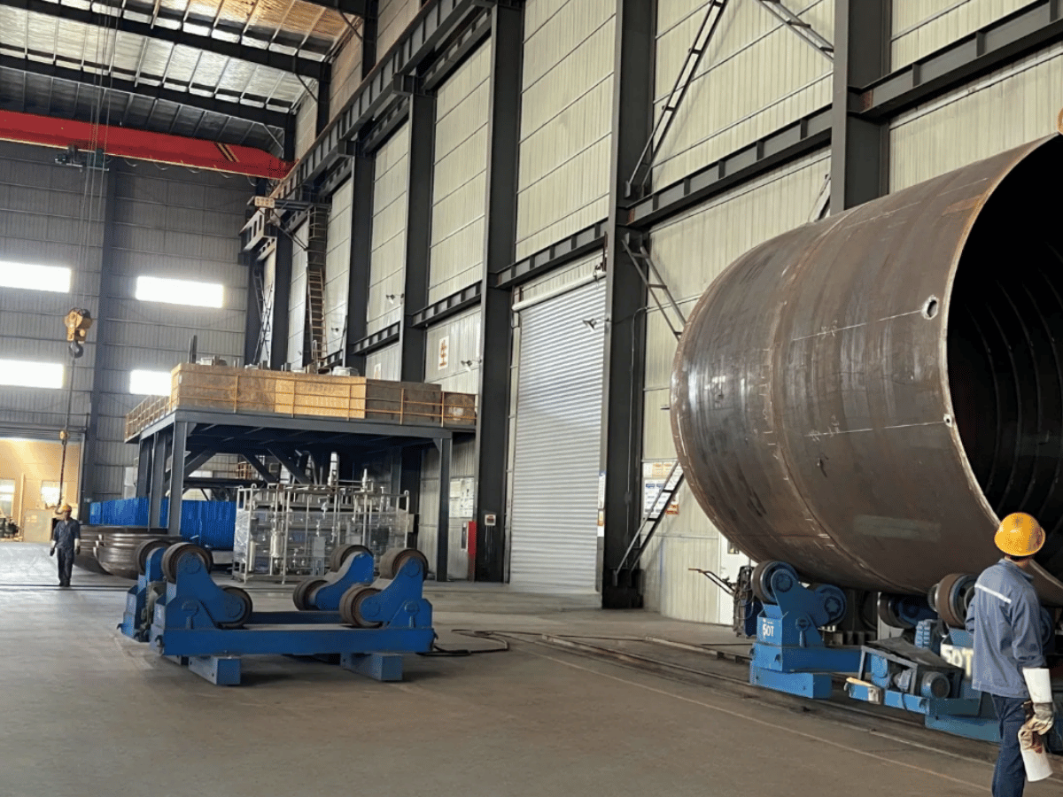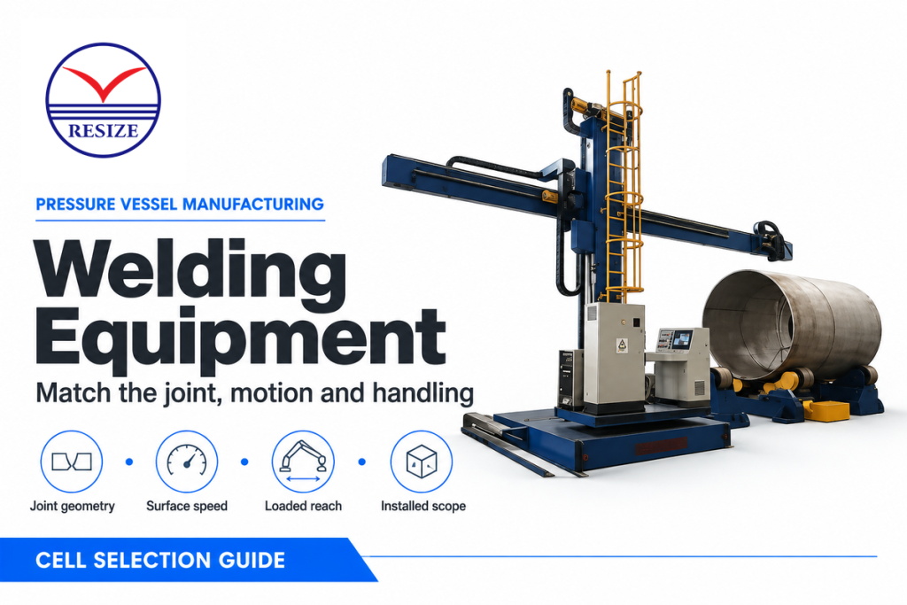
Pressure vessel welding equipment is a matched set of welding power, torch travel and workpiece handling equipment. For accessible girth seams, use turning rolls together with a supported welding head. For longitudinal seams, move the head along the shell.
Choose the process and motion around the joint geometry and qualified welding procedure.
A big vessel may require very slow rotation at the weld with an uneven load from nozzles or attachments. Key welding equipment specifications include surface travel speed, the load on each roll, and the working position of the weld head.
(Updated November 2026)
Match the joint first, then the loaded geometry, travel speed and installation requirements.
Quick Specs: What to Specify
- Rotators: vessel mass, support reactions, diameter range and linear welding speed.
- Manipulators: loaded head reach, vertical clearance and controlled travel.
- Process package: qualified procedure, power source, consumables and controls.
- Installed scope: current return, access, utilities and commissioning.
Choose Pressure Vessel Welding Equipment by Joint
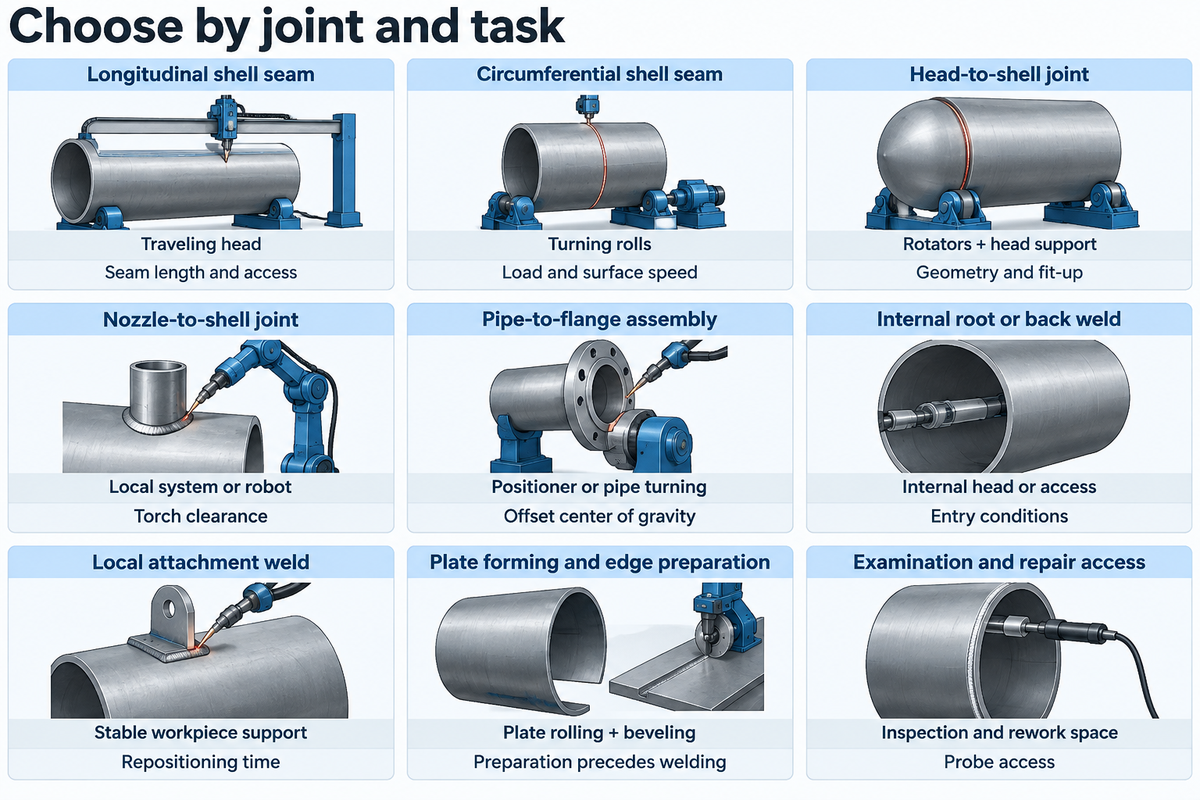
Pressure vessel equipment decisions start with the seam: the longitudinal seam needs travel along the shell, while the circumferential seam can use controlled rotation of the vessel. Nozzle and head welds, meanwhile, produce practical access and positioning needs. Separate the machinery that forms the shell from the machinery that supports the shell throughout welding.
What welding equipment is used in pressure vessel manufacturing?
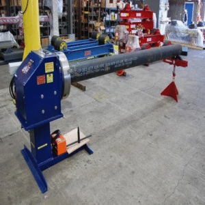
For these welding applications, a full station requires a welding power source, torch or welding head, consumable feed and suitable workpiece support. Automated travel adds a carriage, column-and-boom manipulator or robot. Turning rolls turn suitable cylindrical assemblies; a positioner can rotate smaller assemblies.
Inspection and prep access and extraction should be in the same arrangement.
TWI’s SAW equipment guide describes the power source, wire feed and flux handling behind a submerged arc station. Those process components still need a way to follow the joint. Allocate the welding head and workpiece support separately for each joint in the task map below.
| Joint or task | Equipment and motion | What changes the choice |
|---|---|---|
| Longitudinal shell seam | Traveling head, carriage or manipulator; shell supported | Seam length, joint fit-up and access inside or outside |
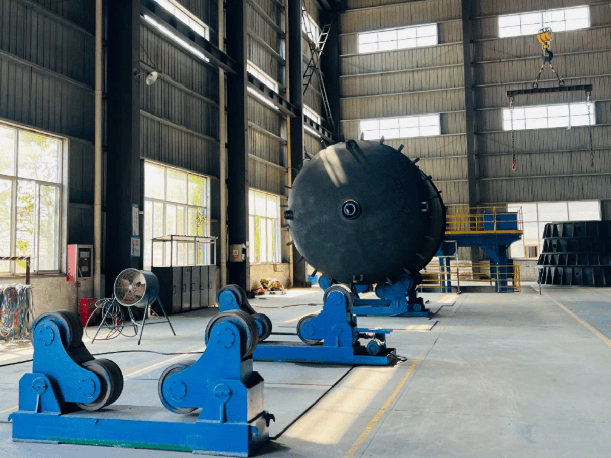
| Circumferential shell seam | Turning rolls rotate the vessel under a supported head | Diameter, load distribution and surface speed |
| Head-to-shell joint | Rotators with head support and suitable welding access | Head geometry, fit-up and changing assembly mass |
| Nozzle-to-shell joint | Positioner, local welding system or robot where suitable | Nozzle angle, surrounding attachments and torch clearance |
| Pipe-to-flange assembly | Positioner or pipe turning arrangement | Offset center of gravity and fixture loading |
| Internal root or back weld | Internal head or controlled personnel access | Opening size, tool envelope and entry conditions |
| Local attachment weld | Manual or mechanized process with stable support | Short seam length, orientation and repositioning time |
| Plate forming and edge preparation | Plate rolling and beveling equipment | Forming duty and joint preparation precede welding |
| Examination and repair access | Planned space for inspection equipment and rework | Required method, probe access and ability to reposition |
Example: A shop builds a carbon steel shell, joins the heads, and adds several offset nozzles. The shell-only phase can have a support pattern that’s different from the finished assembly. After installing the nozzles, the CG has shifted and the turning envelope has expanded; a head that just reaches the bare girth seam may later collide with an attachment.
Mark the fabrication stages in the drawing and, correspondingly, allocate each weld to its actual stage. This also reveals the crane maneuvers between preparation, welding and inspection that faster welding would not eliminate. The handling proposal should cover the heaviest and most awkward stage, not only the clean shell in a catalog photo.
Compare MIG Welding, SAW and GTAW for Pressure Vessels
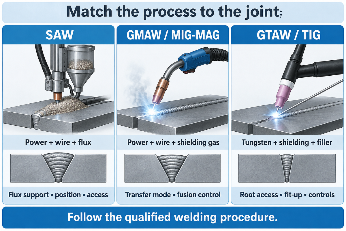
SAW suits accessible seams where the weld pool and granular flux can be supported. GMAW has different transfer modes for different operating conditions. GTAW gives controlled penetration with a non-consumable tungsten electrode and separate filler rod addition.
Match the welding techniques to the qualified joint, material and welding position before selecting the motion equipment.
Which welding process is best for pressure vessels?
For long accessible seams, a mechanized SAW station is a logical candidate. Controlled roots and local work can favor GTAW, while GMAW may be appropriate for other production joints. One vessel can use a number of welding processes.
Select the process for each joint and pass sequence, then specify the power source and handling system collectively.
SAW is a candidate on a head-to-shell girth joint when vessel rotation keeps the weld in the required position and the flux can be supported. A nozzle joint may require local GTAW to give an accessible, controlled root or a qualified GMAW sequence with the right transfer mode. Select the nozzle fixture or robot around access to that joint.
Short-circuit GMAW requires special consideration for fusion; traditional spray transfer leaves a fluid pool and can’t be assumed suitable for every vertical or overhead joint. The qualified procedure must address the actual position and material as well as the pass sequence.
| Proceso | Equipment package | Selection boundary |
|---|---|---|
| Submerged arc welding (SAW) | Wire-feed head, power source, flux delivery/recovery | Flux support, weld position, joint access and qualified heat input |
| Gas metal arc welding (GMAW; MIG/MAG) | Wire feeder, torch, shielding gas, compatible power source | Transfer mode, gas mixture, position and fusion control |
| Gas tungsten arc welding (GTAW; TIG) | Constant-current source, tungsten torch, shielding and optional filler feed | Root access, fit-up, deposition needs and control compatibility |
TWI’s MIG/MAG explanation distinguishes short-circuit, globular, spray and pulsed transfer. Short-circuit transfer uses low heat input, but lack of fusion remains a potential weld defect. Spray and pulsed operation change the power-source duty. In steel fabrication, active shielding-gas mixtures make MAG the more precise term for many jobs commonly called MIG.
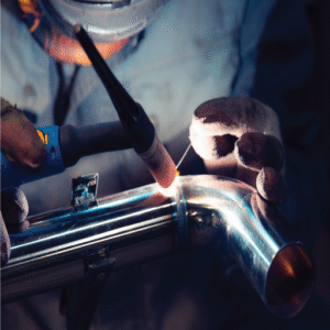
TWI’s GTAW guidance identifies controlled penetration in pipe roots as an application and describes mechanized or orbital systems. Separate filler addition can limit deposition rate on thick fill passes. Shielded metal arc welding (SMAW) may also belong in the approved production sequence. Flux cored arc welding (FCAW) is another option within that sequence. The process name alone doesn’t determine vessel acceptance.
Higher deposition has a cost when it changes the joint properties. Nino Mascalco and Robert Koltz’s pressure-vessel SAW discussion explains that a sound-looking bead can still have poor mechanical properties if heat input is poorly controlled. Treat travel speed, current and voltage as welding-procedure variables, rather than increasing them to meet a machine-output target.
Match Welding Rotators and Manipulators to Vessel Geometry
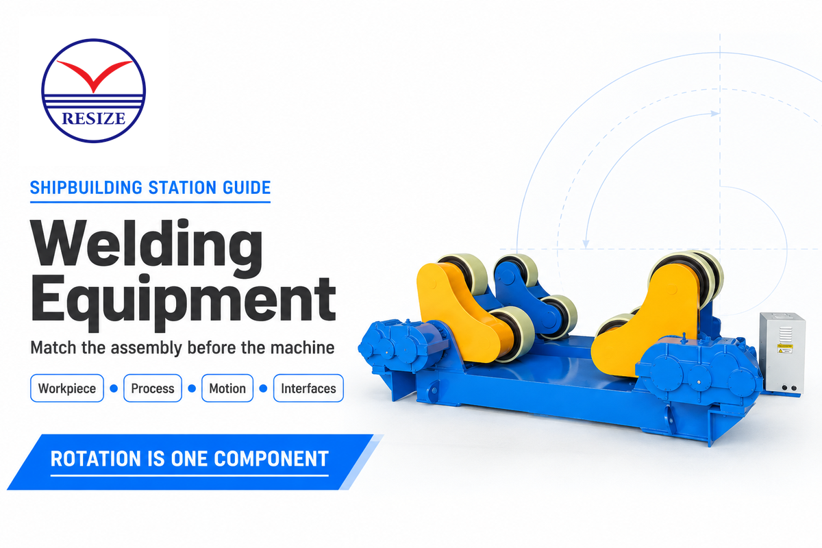
RESIZE’s conventional rotator product card lists 100–1000 mm/min linear speed, while its self-aligning card lists 6–60 m/h. Both show surface travel.
For the desired welding speed, a larger vessel needs fewer rpm. Load support, powered rotation and loaded head reach are three separate equipment-sizing requirements.
El pressure vessel welding rotator range includes different support arrangements. In a roller set, each drive and idler carries part of the mass; the drive must also overcome the torque and traction demand. Extra idlers add support points, but their presence alone doesn’t increase drive torque.
Koike author Ron Krasnek’s AWS article on heavy weldments explains why center of gravity and fixturing matter during positioning. Handling best practices begin with the loaded assembly: nozzles, lifting lugs and fixtures can create offset loads. Conical sections also change contact geometry, so matching the shell diameter is only part of the handling calculation.
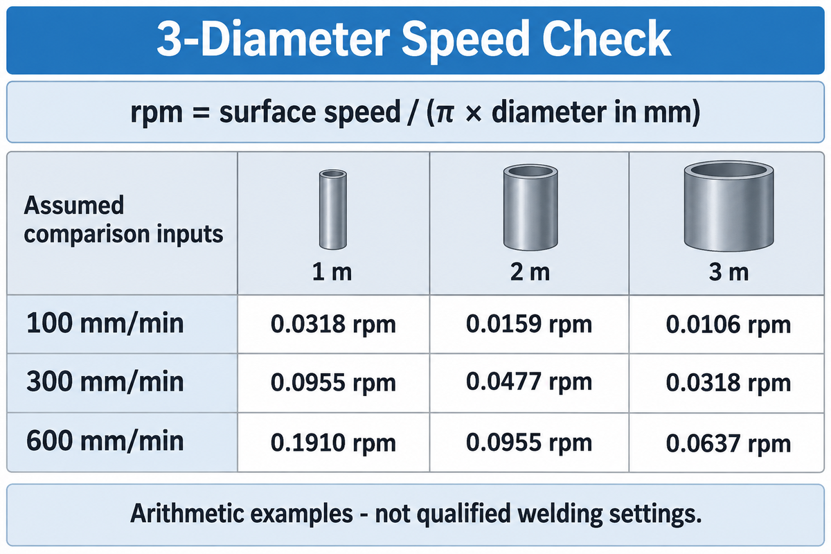
3-Diameter Speed Check
3-Diameter Speed Check calculates the vessel rpm at three diameters from the selected surface speed.
Assumed inputs: vessel diameters of 1, 2 and 3 m, with comparison speeds of 100, 300 and 600 mm/min. These are arithmetic cases to compare motion ranges and aren’t qualified welding settings. The value of diameter should be in millimeters: rpm=surface speed/(π× diameter).
| Surface travel | Vessel diameter | Calculated rotation |
|---|---|---|
| 100 mm/min | 1 m | 0.0318 rpm |
| 100 mm/min | 2 m | 0.0159 rpm |
| 100 mm/min | 3 m | 0.0106 rpm |
| 300 mm/min | 1 m | 0.0955 rpm |
| 300 mm/min | 2 m | 0.0477 rpm |
| 300 mm/min | 3 m | 0.0318 rpm |
| 600 mm/min | 1 m | 0.1910 rpm |
| 600 mm/min | 2 m | 0.0955 rpm |
| 600 mm/min | 3 m | 0.0637 rpm |
At the middle example, 300 ÷ (π × 2,000) = 0.0477 rpm. That low rotational speed is the operating point the drive must hold under the proposed load. Demonstrate this operating point with the proposed load and drive arrangement. For consistent results, the loaded acceptance test should cover low-speed stability, roller contact and axial drift.
Convert units before comparing catalogs: 6 m/h × 1,000 mm/m ÷ 60 min/h = 100 mm/min. Keep the welding-procedure travel-speed requirement separate from the machine’s available speed range.
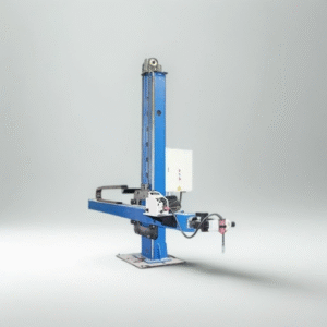
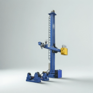
The full welding head package must be supported by a column-and-boom at its working extension. Additional load is imposed by the wire equipment, seam tracking and flux hardware. The RESIZE pipe-manipulator card lists boom forward travel of 0.15-1.5 m/min and travel dimensions up to 8,000 mm.
The proposal also needs a loaded tip-capacity envelope and acceptable deflection at the seam. The column-and-boom sizing guide develops that component calculation.
Select a Welding Positioner for Heads and Nozzles
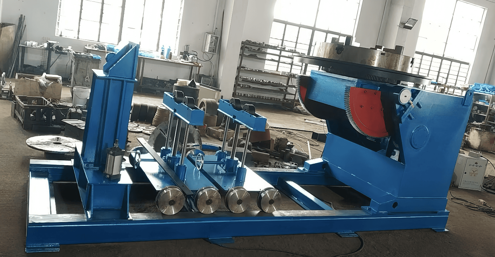
A positioner is useful when the fixture can present a head, nozzle or subassembly in the required orientation. Its loading changes with tilt and center-of-gravity offset. Include the fixture mass and the full sweep of protruding parts; a workpiece that clears the floor horizontally may foul it after tilting. Koike’s Don Burgart explains these positioner-selection factors, including how added assemblies shift the center of gravity. Ask for the permissible load at the proposed offset and tilt, rather than treating the catalog’s maximum mass as valid at every orientation.
ASME Section IX Welding Qualification and Vessel Inspection
ASME Section VIII addresses pressure-vessel construction for pressure containment, while Section IX addresses welding procedure and personnel qualifications. When welding pressure vessels, the fabricator needs the applicable quality system, qualified welding procedures and inspection arrangements alongside capable machinery. Specify the governing code and contract edition in the project specifications prior to choosing the welding package.
El American Society of Mechanical Engineers’ Section VIII Division 1 scope covers design, fabrication, inspection, testing and certification. ASME’s Section IX qualification guidance treats procedures and personnel. Sections VIII and IX of the ASME Boiler and Pressure Vessel Code address different questions in the fabrication of pressure vessels.
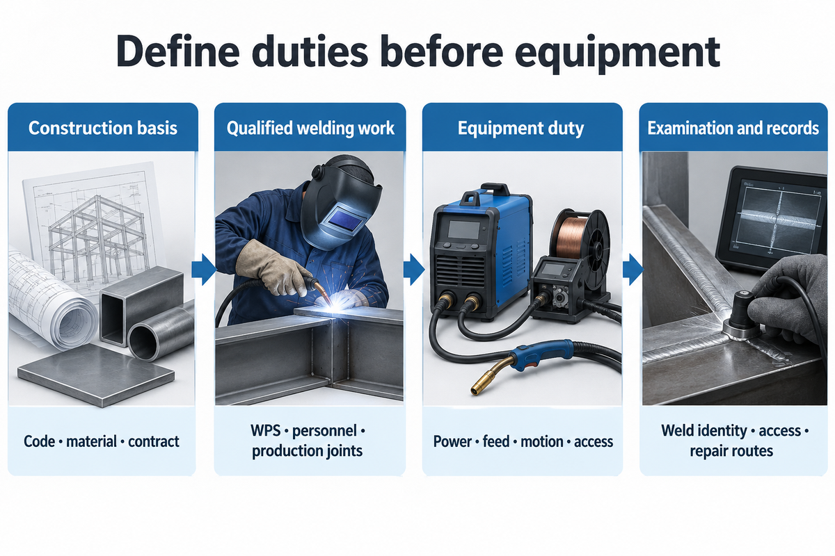
- Establish the construction basis. Identify the governing code, material and contract requirements.
- Define the qualified welding work. Match the WPS and personnel qualification scope to the proposed production joints.
- Specify the equipment duty. Translate the procedure into power, feed, motion and access requirements.
- Plan examination and records. Preserve weld identity, required inspection access and repair routes through production.
The welding procedure specification, supporting procedure qualification and welder / welding-operator qualification have different roles. In automation, the motion is now controlled differently, but it doesn’t mean you don’t need to define and deploy relevant welding requirements.
For projects using ISO operator qualifications, ISO 14732:2025 is the third edition, published in June 2025. It covers operators and setters for mechanized and automatic welding of metallic materials. Keep the specified qualification system explicit when suppliers offer training or operator certification; a training certificate and a code-required qualification are different deliverables.
Compare New and Used Welding Equipment
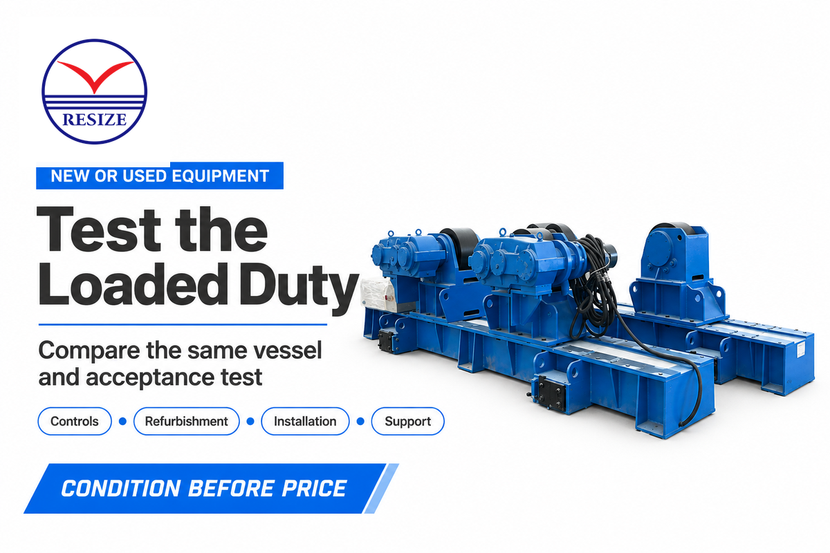
Used welding equipment may be a rational buy if the loaded duty, controls and support are appropriate. New equipment may lower integration uncertainty if the vendor accepts the full scope of integration. Quote out both against the same vessel, welding head and acceptance test then factor in refurbishment, installation and potential outage.
- Specify the required load and speed envelope in the order.
- Allocate controls and integration work before manufacture.
- Include training, documentation and service scope in the price.
- Demonstrate the required duty on the offered machine.
- Price control repairs and interface changes before purchase.
- Check documentation, available spares and service support.
Imagine a used roller-and-manipulator that works well in a showroom test. The proposed welding head adds weight at full extension, and you must rotate slowly during production for a full revolution. A rigorous test reproduces those conditions, including repeated starts and stops, using the intended welding power supply.
TWI observes that HF arc start can upset nearby electronic controls. This defines the real issue for the purchase, not an automatic turnoff for old equipment. Cost out the solution before comparing the package to a new installation.
If you can’t get support for the drive or controls, weigh the potential savings against the cost of refurbishing the older machine and the risk of operating without support.
NIST’s equipment pre-purchase guide covers utilities, ancillary purchases, maintenance and training. Apply that cost scope to both options, including the condition checks for a used welding positioner.
Calculate the Cost of a Productive Welding Cell
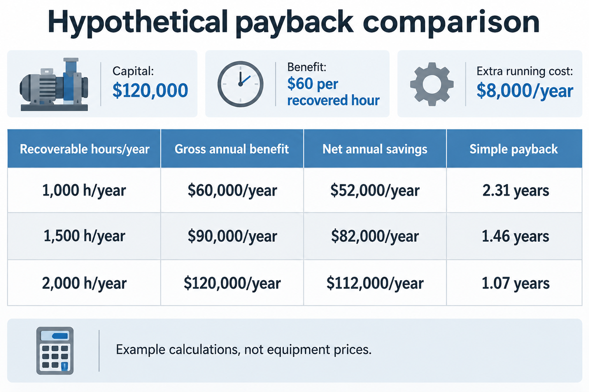
With assumed installed capital of $120,000, an avoidable cost of $60 per recovered hour and $8,000 in extra annual running costs, 1,500 recoverable hours per year gives about 1.46 years’ simple payback. These inputs are used to demonstrate the calculation; they are not equipment prices or a RESIZE quotation.
Installed capital includes the machines, tooling, controls, foundations or floor work, utilities and commissioning. NIST’s purchasing questions help expose costs outside the machine price. Separate annual cash savings from capacity that remains unused, and avoid counting the same released hour as both labor savings and additional output.
| Recoverable hours/year | Gross annual benefit at $60/h | Net annual savings | Simple payback |
|---|---|---|---|
| 1,000 h/year | $60,000/year | $52,000/year | 2.31 years |
| 1,500 h/year | $90,000/year | $82,000/year | 1.46 years |
| 2,000 h/year | $120,000/year | $112,000/year | 1.07 years |
For the middle row, annual net savings = (1,500 h/year × $60/h) − $8,000/year = $82,000/year. Simple payback = $120,000 ÷ $82,000/year = 1.46 years. A two-year target in the same model requires at least 1,134 recoverable h/year, rounded upward.
Example: automation generates shop time but there isn’t additional work; the same crew gets paid and that time is just more useful capacity. That ‘useful’ capacity is relevant if there’s enough work, but added time hasn’t saved the shop money. A credible model could include avoided overtime, outsourced work brought in-house, or the incremental contribution from saleable output, but there are separate assumptions for each.
If inspection is already the limiting factor, faster welding may only generate a backlog. Track fit-up, arc time, interpass work, inspection and rework individually before assigning an annual benefit. Simple payback also excludes financing, tax and the time value of money, so finance may require a more detailed investment evaluation.
How Welding Positioner Price Fits a Cell Budget
Positioner price is one line of your installed budget. Include fixtures, current-return hardware, control interfaces and delivery to the operating location. Compare the price to the supported load and orientation throughout the project, then spread maintenance and spare-part costs over the anticipated lifetime.
Choose Welding Rotator Manufacturers and System Suppliers
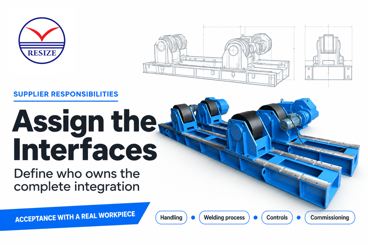
Select a new equipment supplier based on the equipment responsibilities they are willing to accept: handling, welding process, controls or complete integration. A good rotator manufacturer combined with a good power-source supplier can still leave the interface unassigned. Designate synchronization, interlocks and commissioning to a named owner and include a representative workpiece in the acceptance.
For a handling package, RESIZE supplies welding rotators, manipulators and positioners. Koike describes turning-roll systems y Koike’s sizing guidance for column-and-boom manipulators in its equipment-sizing guidance. For adaptive robotic nozzle welding, Pemamek describes a PEMA installation at NWP that combines scanning, material handling, a welding-robot gantry and Lincoln Electric welding equipment. These examples cover different equipment scopes; compare them against the joints and handling duties in the project specification.
A vessel-cell proposal should identify which process equipment and integration services are included. Adam White’s robot-buying guidance published by AWS recommends proving the system with representative parts before shipment; the integrator can be a different company from the robot manufacturer.
“give them your best and worst parts and ask for a proof of concept.”
A useful acceptance package includes the proposed head, representative fixture and difficult access conditions. For service reliability, note who supplies spare controls, backs up programmes, and supports faults following commissioning. Those roles are especially helpful if multiple firms have supplied equipment to a single cell.
Plan Installation, Access and Inspection
A vessel welding cell needs room for the complete rotating envelope, operator access, current return and the required examinations. Resolve these requirements on the layout before ordering equipment since longer booms can’t solve all access and servicing problems.
OSHA 1910.254 addresses the welding-current return circuit, including bonded joints or current-collecting devices where fixtures regularly form part of the circuit. Protective grounding is a different function. Provide a return path for production current in the circuit.
For servicing, OSHA 1910.147 differentiates between energy isolation and control-circuit stopping. Push buttons and selector switches aren’t recognized as energy-isolating devices. To help ensure safety during servicing, the machine-specific energy-isolation procedure must address the relevant electrical, hydraulic and other sources of hazardous energy.
OSHA’s confined-space welding provisions require ventilation and place gas cylinders and welding machines outside the confined space. Entry through a small opening also requires arrangements for emergency removal. Under OSHA 1910.146, the employer evaluates whether a space is permit-required; applicable permit programs include testing, ventilation, communication and rescue equipment. Assess the actual vessel and work, rather than classifying every new shell alike.
Pressure Vessel Welding Distortion and Inspection Access
Fit-up and weld sequence affect how the assembly moves during fabrication. Preserve access for the specified nondestructive testing and for any repair excavation. High-quality welds require more than an acceptable appearance. A visually sound weld can still contain a flaw, so inspection planning must address the required method, extent and acceptance criteria for vessel integrity. Tony Hufford’s fabrication-preparation guidance also highlights cleanliness and contamination control, including the risk of transferring a contaminant to stainless steel.
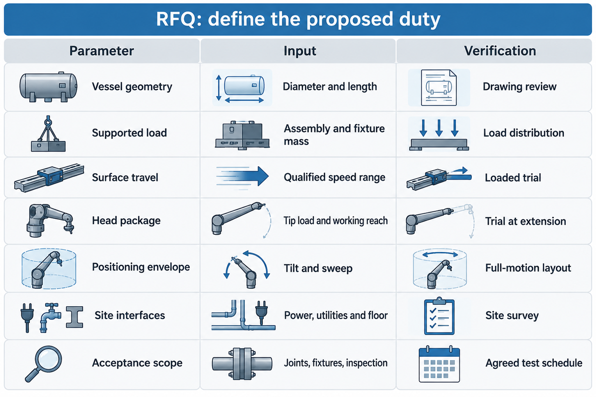
Paste these fields into the RFQ and fill them from the vessel drawings and procedure. If the calculation of the example speed is applicable, add the low speed running points you need.
| Parámetro | Recommended range | Why it matters | How to verify |
|---|---|---|---|
| Vessel geometry | Minimum and maximum diameter in mm; length in mm | Changes contact and access | Drawing review at each fabrication stage |
| Supported load | Assembly and fixture mass in kg; support reactions in kN | Sets each roll duty | Supplier load-distribution calculation |
| Surface travel | Qualified minimum and maximum in mm/min | Sets loaded speed control | Representative loaded trial |
| Head package | Complete tip load in kg and working reach in mm | Changes boom deflection | Load-envelope review and trial at extension |
| Positioning envelope | Required tilt in degrees and sweep in mm | Exposes floor or attachment collisions | Layout and full-motion review |
| Site interfaces | Available V/Hz; utility and floor requirements | Prevents installation omissions | Site survey and electrical/interface schedule |
| Acceptance scope | Named joints, fixtures and inspection criteria | Makes proposals comparable | Agreed test and responsibility schedule |
Preguntas frecuentes
Can you weld a pressure vessel?
Yes, pressure vessels can be manufactured by welding when the design, materials, welding procedures, personnel qualifications and inspection satisfy the applicable construction requirements. The selected equipment must provide the motion, joint access and controls needed by the qualified production procedure. Welding an existing vessel introduces a different assessment of service history, contents and the rules for repair or alteration; it’s outside this manufacturing-equipment guide.
Does a welding machine need an ASME U stamp?
No. The ASME U designation concerns pressure-vessel manufacture within the certification program, rather than general approval of a welding power source or handling machine. The fabricator’s applicable authorization, quality system, qualified procedures and inspection obligations must be addressed alongside equipment capability. A machinery purchase and a vessel certification decision are separate parts of the project.
Can one setup weld carbon steel and stainless steel?
Yes, one mechanical setup can handle both when its load, geometry and temperature duties fit the jobs. Welding still requires the appropriate procedure, consumable, shielding and preparation for each material. Stainless steel work also needs stringent contamination control. Dedicated or suitably controlled preparation tools and contact surfaces help prevent material transfer during fabrication and handling.
Are plate rolling machines and welding rotators the same?
No. Plate rolling machines form flat plate into curved shells. Welding rotators support and rotate assembled cylindrical workpieces during welding or related operations. Forming capacity and welding support capacity describe different duties.
Does every pressure vessel weld require radiographic inspection?
No, radiography isn’t required for every pressure vessel weld. The applicable construction code, design and contract establish the examination methods and extent. Ultrasonic examination, radiography, magnetic particle testing and penetrant testing have different applications; the responsible engineer and inspector define the required scope.
Will more idler rolls increase turning capacity?
More idlers can add support points, but they don’t automatically increase the drive’s turning capacity. The proposed arrangement still needs adequate drive torque, traction and load distribution throughout rotation.
What information should I send for a vessel welding equipment quote?
Send drawings, material, fabrication stages, diameters, assembly mass and weld locations. Add the complete head package, required speed range, available layout and utilities. Identify the party responsible for the welding process, handling controls, installation and acceptance testing.
Various types of pressure vessels need different support arrangements: Spherical vessels need a different support geometry from cylindrical shells. The construction requirements for high-pressure process equipment are adapted to a different set of parameters. Components produced for nuclear power aren’t included in the conventional shop-cell scope discussed here.
Boilers and pressure vessels are subject to different construction rules from atmospheric storage tanks.
Define the Vessel Cell with RESIZE

Start with the vessel drawing and weld sequence, then match the handling arrangement to the process. Review our welding manipulators y discuss the vessel and weld layout with RESIZE.
Artículos relacionados
- Pipe rotators for welding: support and rotation choices
- How to choose a welding positioner
- ISO 3834-2 welding quality requirements
- Seam tracking for mechanized welding
References & Sources
- TWI: Equipment for submerged arc welding
- TWI: MIG/MAG welding and transfer modes
- TWI: Tungsten inert gas welding
- The Fabricator: Optimizing SAW on pressure vessels
- American Welding Society: Handling heavy weldments, May 2026
- American Society of Mechanical Engineers: BPVC Section VIII, Division 1
- American Society of Mechanical Engineers: Section IX qualifications
- International Organization for Standardization: ISO 14732:2025
- National Institute of Standards and Technology: Equipment pre-purchase guide
- American Welding Society: Considerations for your first welding robot, October 2025
- Occupational Safety and Health Administration: 29 CFR 1910.254
- Occupational Safety and Health Administration: 29 CFR 1910.147
- Occupational Safety and Health Administration: 29 CFR 1910.252
- Occupational Safety and Health Administration: 29 CFR 1910.146
- The Fabricator: Welding prep in pressure-vessel fabrication
This guide for equipment selection uses the preceding references, and the stated assumptions apply to the example calculations. The basis for production is the vessel design, the welding procedure and the inspection requirements.