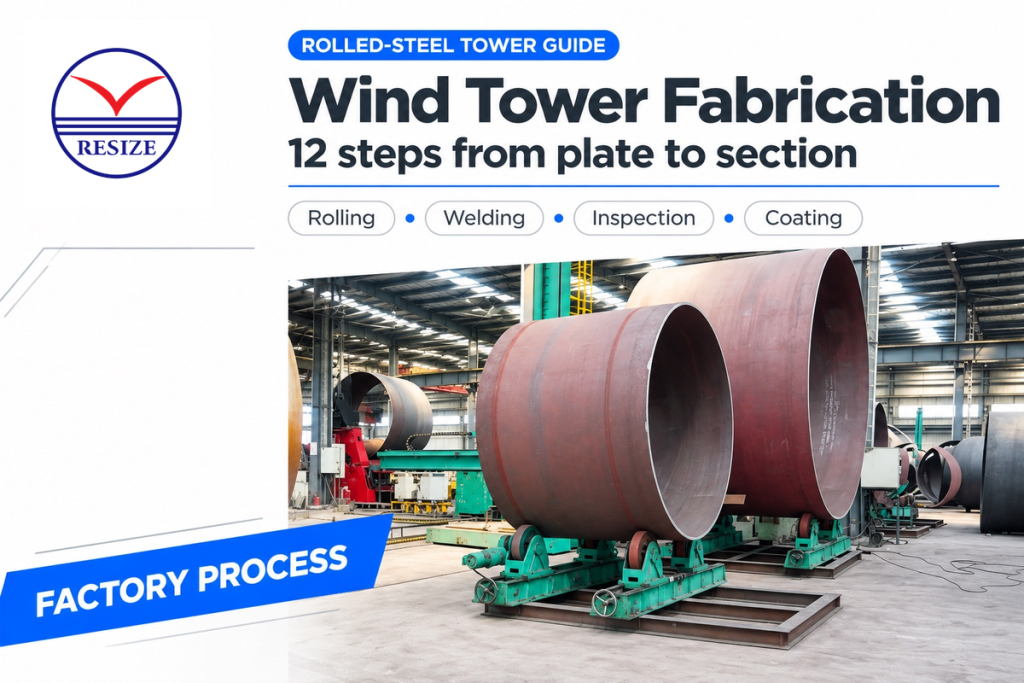
The production process for a wind tower consists of cutting, beveling, rolling, welding, inspection and coating of steel plate to produce transportable sections. A wind tower is the load bearing tubular tower structure below the turbine. This guide follows the conventional rolled-plate route, from identified material to a completed section ready for shipping.
Wind tower fabrication process is the factory sequence that turns steel plate into welded, inspected and coated transport sections. Rolling makes individual cans; circumferential welds join cans into sections. Bolted connections join the sections on-site.
- A faster welding head can leave finished output unchanged if coating or handling limits the line.
- One rolled can, one transport section and one complete tower are different production units.
- Minimum diameter and material strength belong beside thickness in a rolling-machine specification.
- Monopile dimensions describe foundations; they must stay separate from tower-machine requirements.
Rolled steel plate to finished transport section
12 factory operations, with checks throughout
Cutting, beveling, rolling, welding and handling stations
Can → transport section → complete tower
The twelve divisions cover a typical walkthrough. Approved drawings, material specifications, welding procedures, inspection plans and transport rules control the production process. The factory makes the steel shell and its interfaces; a wind turbine blade, nacelle, foundation and field erection belong to separate work packages.
Updated October 2026
Wind tower fabrication process: 12 steps from plate to section
How does wind tower fabrication work?
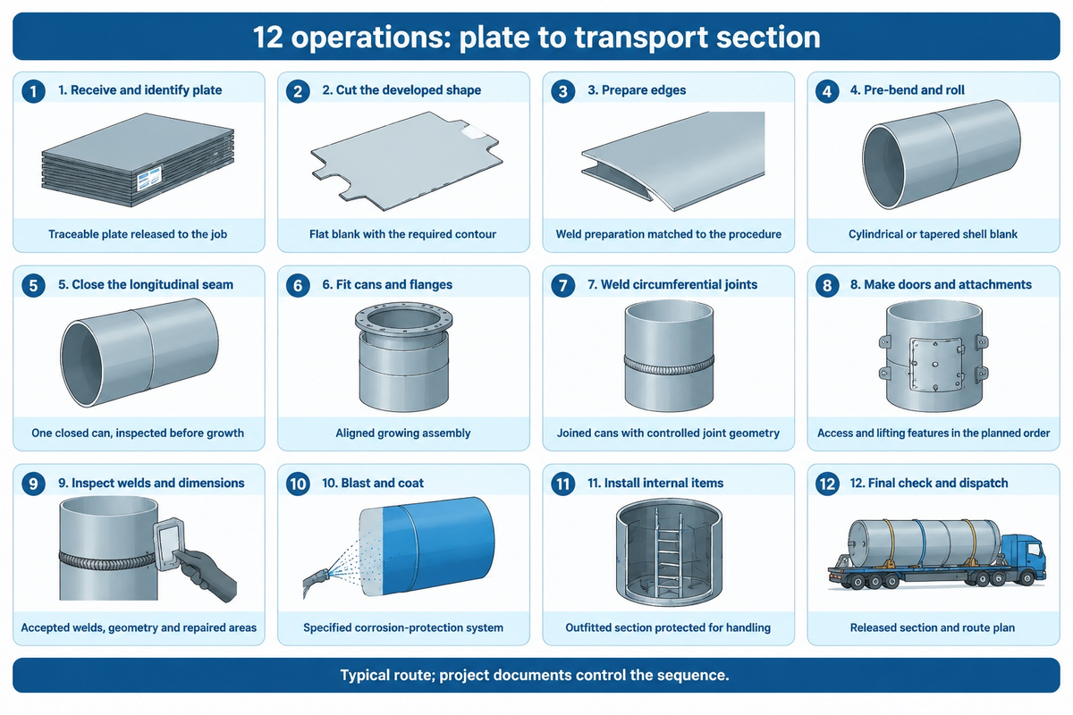
Fabrication starts with identification of the plate, cutting to length and beveling the edges. Rolling forms each blank into a can; longitudinal welding closes it. Fit-up and circumferential welding build the transport section. Attachments, inspection, corrosion protection, internals and dispatch complete the route. The sequence includes intermediate checks to confirm conformance before the next operation restricts access.
“Made from tubular steel, the tower supports the structure of the turbine.”
The Department of Energy states that towers usually arrive in three sections for on-site assembly. The number of cans in each section is according to design and factory plan. The steel tower supports the rotor and nacelle loads; the wind turbine installation team joins the transport sections at the wind turbine site.
| Step | Operation | Typical machine family | Output or control point |
|---|---|---|---|
| 1 | Receive and identify plate | Material handling, marking and records | Traceable plate released to the job |
| 2 | Cut the developed shape | CNC flame or plasma cutter | Flat blank with the required contour |
| 3 | Prepare edges | Milling or beveling machine | Weld preparation matched to the procedure |
| 4 | Pre-bend and roll | Plate rolling machine | Cylindrical or tapered shell blank |
| 5 | Close the longitudinal seam | Fit-up tools, manipulator and seam welder | One closed can, inspected before growth |
| 6 | Fit cans and flanges | Fit-up rotator, fixtures and cranes | Aligned growing assembly |
| 7 | Weld circumferential joints | Rotator and automated welding equipment | Joined cans with controlled joint geometry |
| 8 | Make doors and attachments | Fabrication, positioners and local welding tools | Access and lifting features in the planned order |
| 9 | Inspect welds and dimensions | Inspection and measurement equipment | Accepted welds, geometry and repaired areas |
| 10 | Blast and coat | Surface preparation and coating line | Specified corrosion-protection system |
| 11 | Install internal items | Platforms, ladders, cable supports and fixtures | Outfitted section protected for handling |
| 12 | Final check and dispatch | Dimensional, lifting and transport controls | Released section and route plan |
A can is an individual shell made from a blank and closed with a longitudinal weld. A transport section contains several cans joined in the factory, often with end flanges and attachments. Several transport sections form a complete tower during erection. Counting cans as finished sections overstates the output available for dispatch.
Why use a steel tubular tower for wind turbines?
A steel tubular tower carries the turbine above ground in a load-bearing shell that can be fabricated and shipped in sections. A tower for a wind turbine must match the turbine’s structural interfaces as well as the delivery route. Rolled-steel construction places shell forming, joint welding and flange fit-up within a repeatable factory sequence.
Steps 1–3: steel plate receiving, cutting and beveling
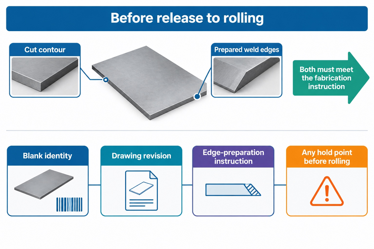
Receiving connects the material certificate and job identity to each plate before cutting. The specified grade, toughness and thickness travel with the blank through the line. Wall thickness and blank geometry can change along the tower, so the drawing revision must stay attached to the part through cutting, beveling and rolling.
Nesting and kerf allowances affect material use; a cleanly cut edge still needs its weld preparation. Step 3 is the separate edge-preparation operation: milling or beveling establishes the joint geometry required by the qualified welding procedure. The RESIZE milling and beveling machine is referenced on the equipment page, and the actual angle, land and root gap are project-controlled values.
The record also gives the quality team a place to attach cut and bevel inspection results. A traveler or digital job record should identify the blank, drawing revision, edge-preparation instruction and any hold point before rolling. This is where a line layout either protects traceability or creates a later search through mixed plate bundles.
Define the blank family before selecting the cutter. A tower program can incorporate straight-sided blanks, tapers, and door openings. A laser cutting machine or thermal cutting system has to be evaluated against the actual part family, including edge treatment and loading. Maximum cutting thickness alone leaves the usable blank length and width unresolved.
Steps 4–5: rolling cans and longitudinal seam welding
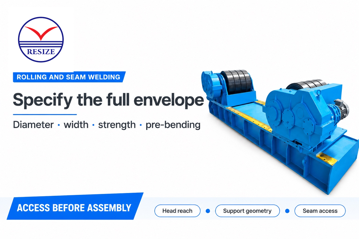
Rolling bends a flat blank into cylindrical shells or tapered steel cans. The smallest diameter, plate width, material strength and pre-bending requirement define the usable machine envelope. The capacity to pre-bend can be less than the rolling capacity of the same machine for the same diameter and material. Therefore, in such a case, compare both the ratings. A conical tower requires the taper to be controlled as the blank passes through the rolls. Shell segments must meet at the intended joint without forcing a damaged edge into alignment.
In a Practical Machinist thread on plate rolling, a buyer was advised to also state a minimum diameter with the plate thickness. That’s good purchasing advice. That is a useful purchasing prompt: compare the complete job mix, including its smallest can, rather than a single favorable rating.
Steve Bonnay’s 2010 Rolling for Wind article reports rolling alone taking 5–10 minutes in the example described, followed by another 10 minutes of tack welding that keeps the rolling machine occupied. The workpiece remains at the station after bending ends; station occupancy must include both rolling and tacking time. Bonnay was a Davi regional sales manager, so this is a dated, commercially informed example.
It’s important to protect the bevel during the forming operation. In a 2017 Fabricator article on wind component fabrication, continuous edge guidance during plate rolling is described in a rolling-system interview to prevent damage to prepared edges, and damage to prepared edges creates rework before the seam is closed.
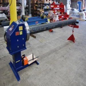
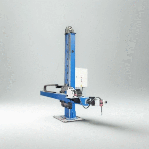
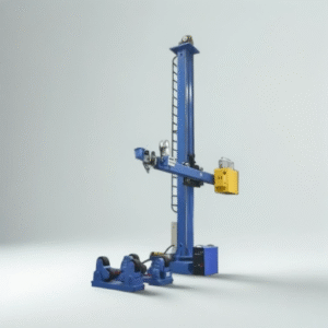
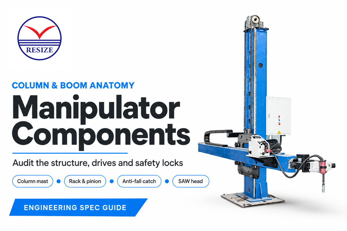
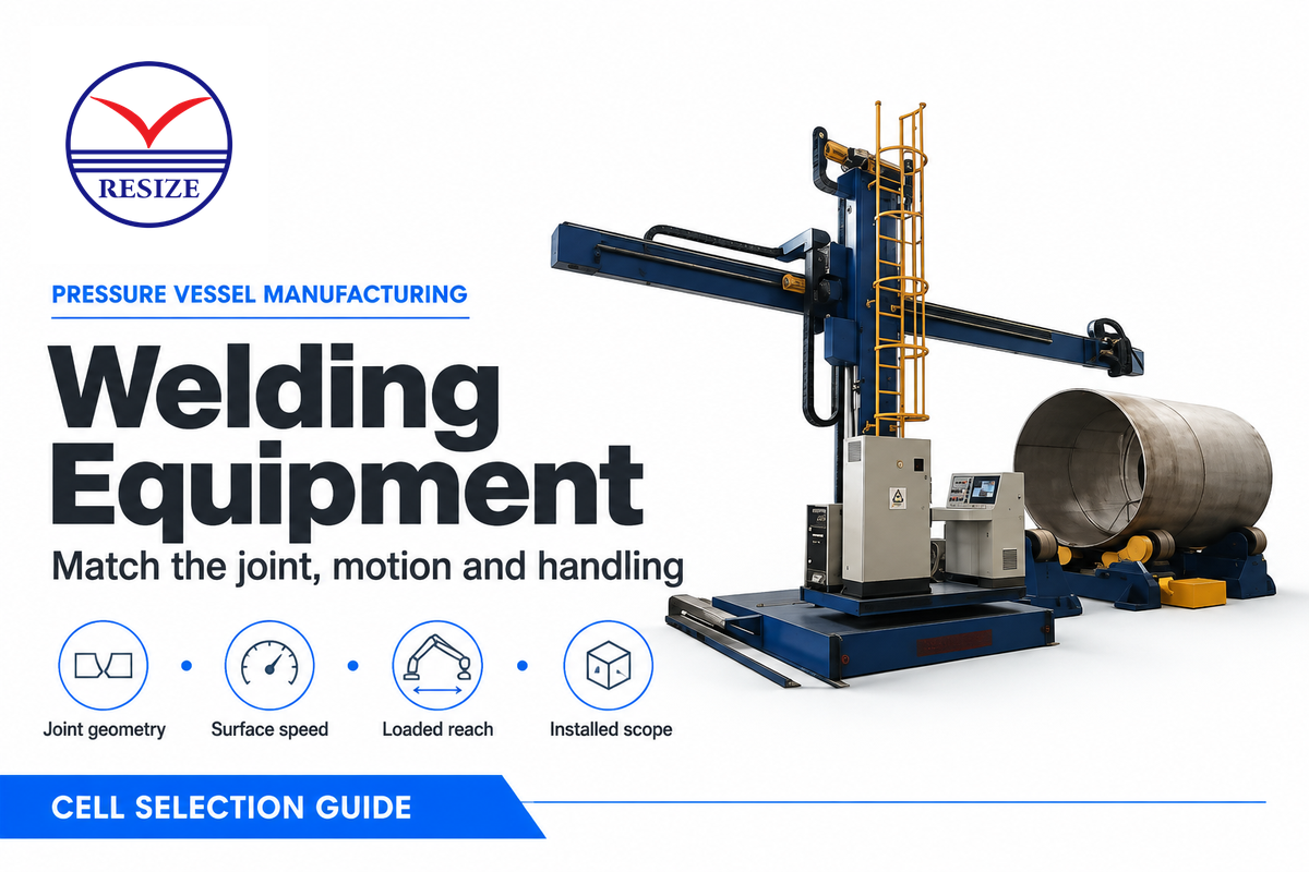
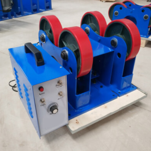
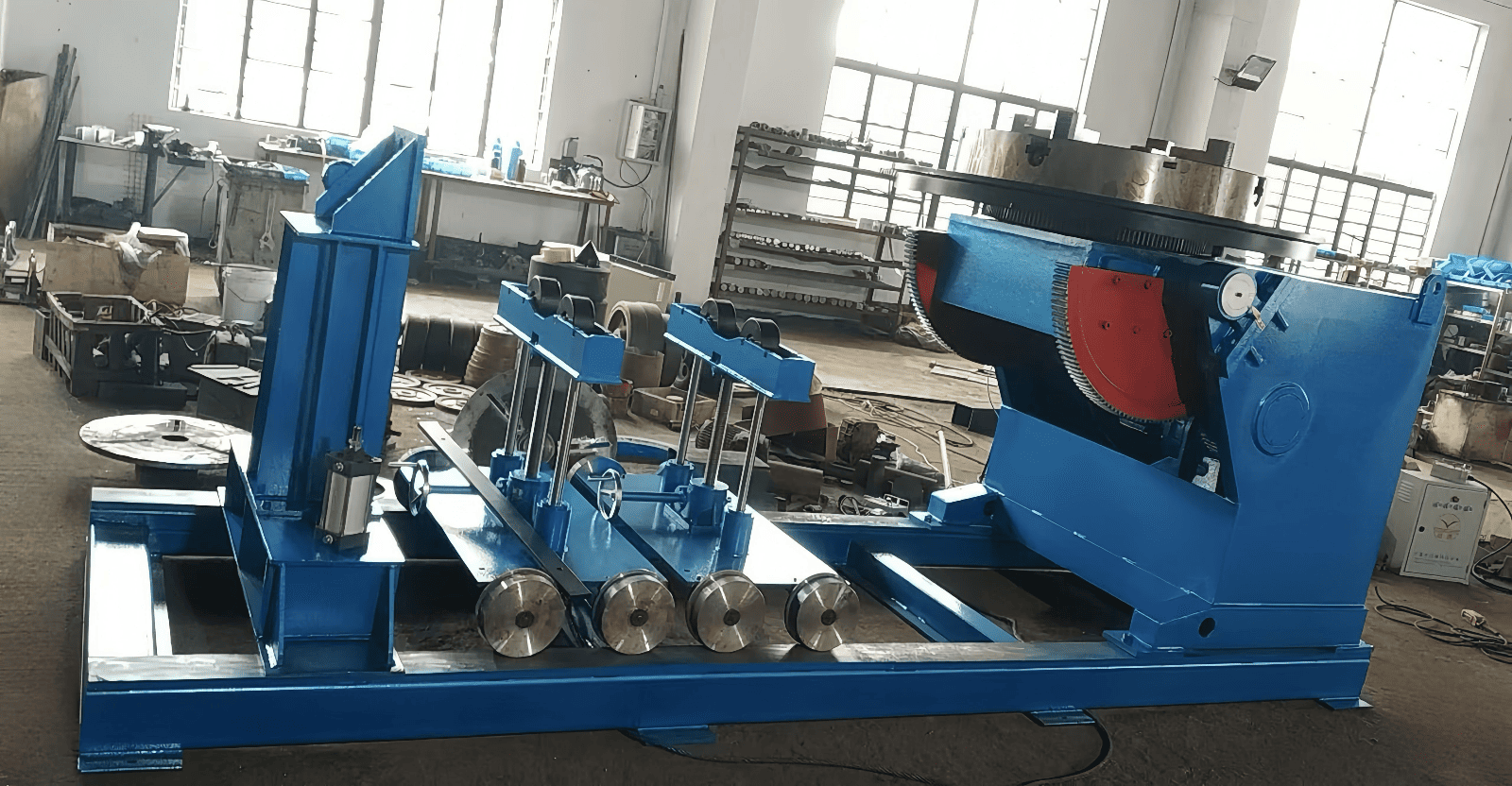
After the edges meet, the can is aligned, tacked, and welded along the straight seam. A lasmanipulator positions the head; a rotator supports controlled turning where required. RESIZE’s welding manipulators and welding rotators cover these functions. Head reach and support geometry have to permit access to the seam for welding and inspection.
Inspect the seam while the can remains accessible. Flanges, door frames and internal items can restrict later access to the same weld. Precise welding begins with joints that are prepared and a stable fit-up. Automation can’t align a shell that’s incorrectly positioned, by itself.
Steps 6–8: flange fit-up, circumferential welding and attachments
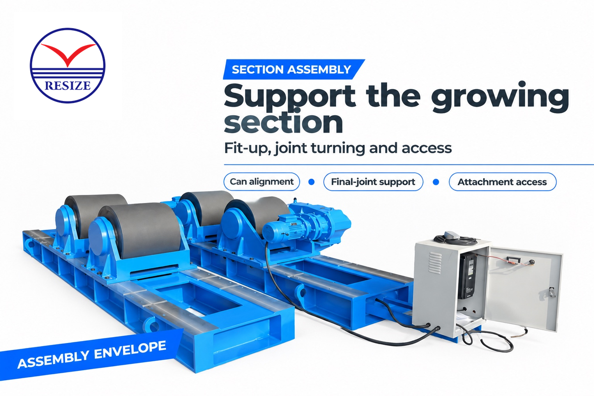
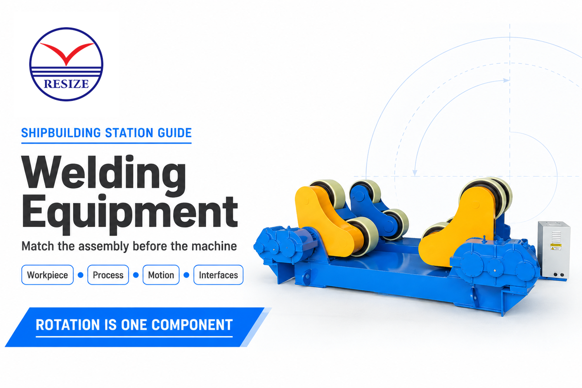
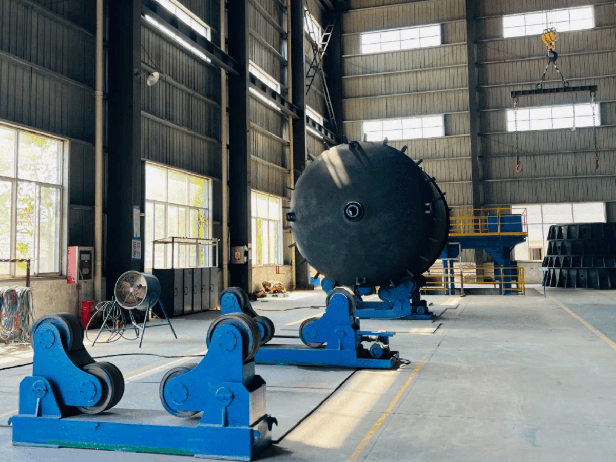
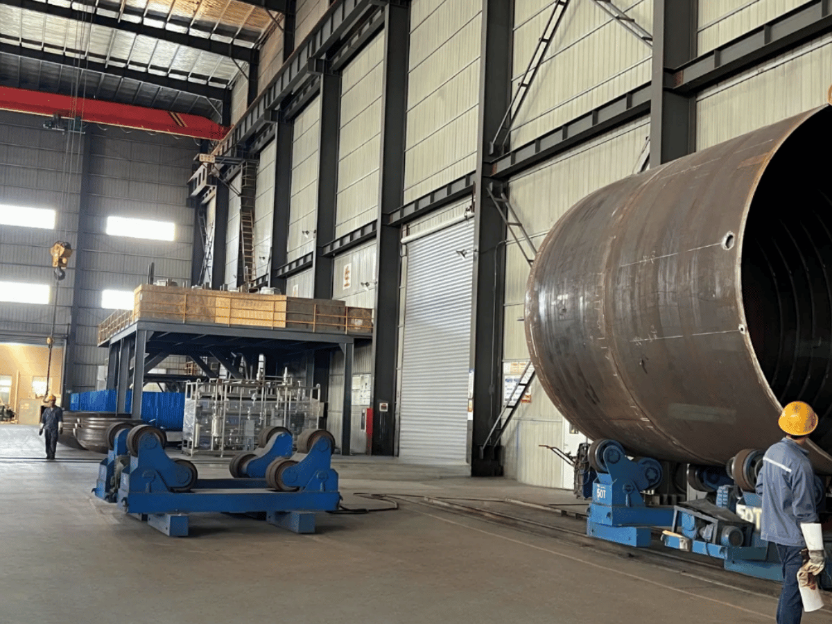
Cans are aligned and welded together to form one transport section. Flange fit-up controls the end interface while the support system carries the growing assembly. A fit-up rotator aligns the joint; the welding station then maintains the required movement and head access. RESIZE’s fit-up rotator page describes the alignment equipment used at this handoff.
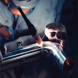
In step 7, the aligned cans are turned while the circumferential joint is welded. A 2006 Aerisyn case published by The Fabricator describes cans clamped together, tack welded and joined by automatic submerged arc welding. Its sequence illustrates why welding automation still needs internal and external access, controlled fit-up and a repair route.
The support envelope increases with each added can. A complete tower section requires adequate support throughout the weld sequence, including the final joint. A rotator sized only for the first can leaves the last assembly operation unresolved.
Step 8 covers door frames, lifting points and welded supports for internal items; the illustrated route installs platforms and ladders in step 11 after coating. Installation of the platforms and ladders may occur earlier or later in the sequence, as dictated by the drawing, coating system or lifting plan. Keep the attachment list tied to the section drawing, so that a machine quote doesn’t omit cranes, fixtures and local welding work.
| Question for the line quote | Why it changes the result |
|---|---|
| What is the maximum supported diameter and section length? | It defines the handling envelope, not only the rotator nameplate. |
| How is flange runout measured? | Small post-weld deviations can affect bolt preload and fatigue behavior. |
| Where are doors and attachments welded? | The answer changes access, crane occupancy and coating repair. |
Steps 9–10: weld inspection and corrosion protection
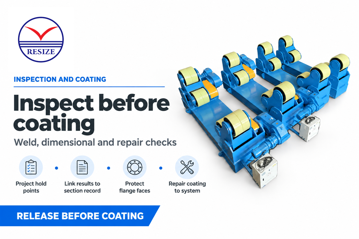
Weld and dimensional checks take place throughout manufacture and before coating covers the steelwork. Inspection includes the examinations and repair checks specified for the project. ISO 3834-2:2021 defines quality requirements for fusion welding in workshops and at field installation sites. Structural design, welding procedure qualification, weld acceptance and coating requirements remain distinct parts of the project specification.
Coating consumes floor space and time after welding is completed. The system of protection is also affected by weather, exposure and the environment. Plan the surface-preparation route and cure occupancy with the welding line so that unfinished steelwork does not accumulate at the paint-shop entrance.
Inspect the tower according to the approved hold points before releasing it for coating. Keep weld identity and dimensional results linked to the section record. After coating, protect flange faces and machined interfaces during handling. Coating repairs at attachment or lifting areas must follow the selected protection system.
Steps 11–12: wind tower internals and transport
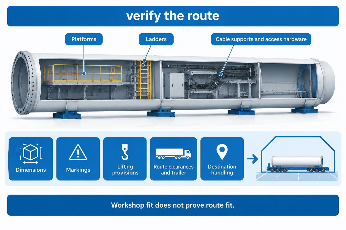
Internal outfitting adds platforms, ladders, cable supports and access hardware before final release. Steel tower sections are protected and transported to the site in the planned order of erection. A dispatch check covers the dimensions, markings and lifting provisions as well as route clearances and the trailer, and the arrangement for the handling of the load at destination.
Factories prefabricate transport sections rather than finishing an entire tower and cutting it apart. Route planning is initiated while the decisions on the location of flanges and section length are still open. A large diameter section may fit the workshop but exceed the road transport or port-handling envelope.
The Department of Energy states that challenges related to transportation and logistics limit the height and size of the towers that can be deployed. That’s also a manufacturing decision: changing section length, flange location, and temporary supports and packing can alter line layout.
Wind tower fabrication equipment and production capacity
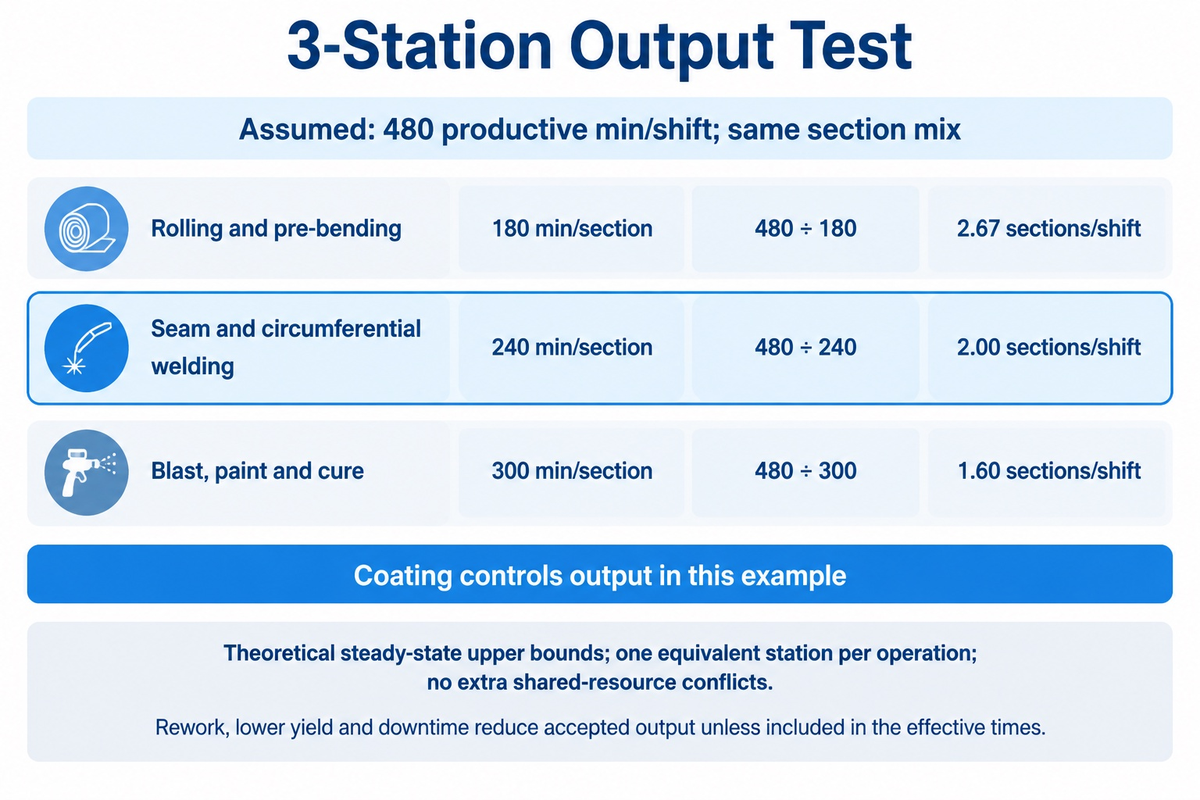
When balancing a line, the useful unit is the number of transport sections accepted per shift. Cutting speed, rolling time and weld travel speed measure different operations.
3-Station Output Test
Use the 3-station output test to determine which of the three operations, rolling, welding and coating, has the lowest station capacity on an accepted section basis.
Assumed inputs: 480 productive minutes per shift; the same section mix at each station; effective times of 180, 240 and 300 min/section. Each value includes the work assigned to that station. These are theoretical steady-state upper bounds with one equivalent station per operation and no extra shared-resource conflicts. Rework, lower yield and downtime reduce accepted output unless already included in the effective times.
| Illustrative station | Effective time per section | 480 productive min/shift ÷ time | Decision implication |
|---|---|---|---|
| Rolling and pre-bending | 180 min | 2.67 sections/shift | Not the constraint in this example |
| Seam and circumferential welding | 240 min | 2.00 sections/shift | Improving this alone does not increase finished output in this example |
| Blast, paint and cure | 300 min | 1.60 sections/shift | Controls finished output in the example |
Decreasing welding from 240 to 160 min/section increases welding capacity from 2.00 to 3.00 sections/shift. Shared cranes, downtime, rejected work and changing section sizes require a fuller schedule.
Refer to the “RESIZE wind tower Production Line” page for a discussion on equipment scope for a production line. Manufacturing wind turbine towers requires matching that scope to the section family. Lines with a greater volume of tons of steel can still dispatch fewer accepted sections with each section containing more weld work or occupying the coating station longer.
Onshore and offshore wind turbine towers: what changes
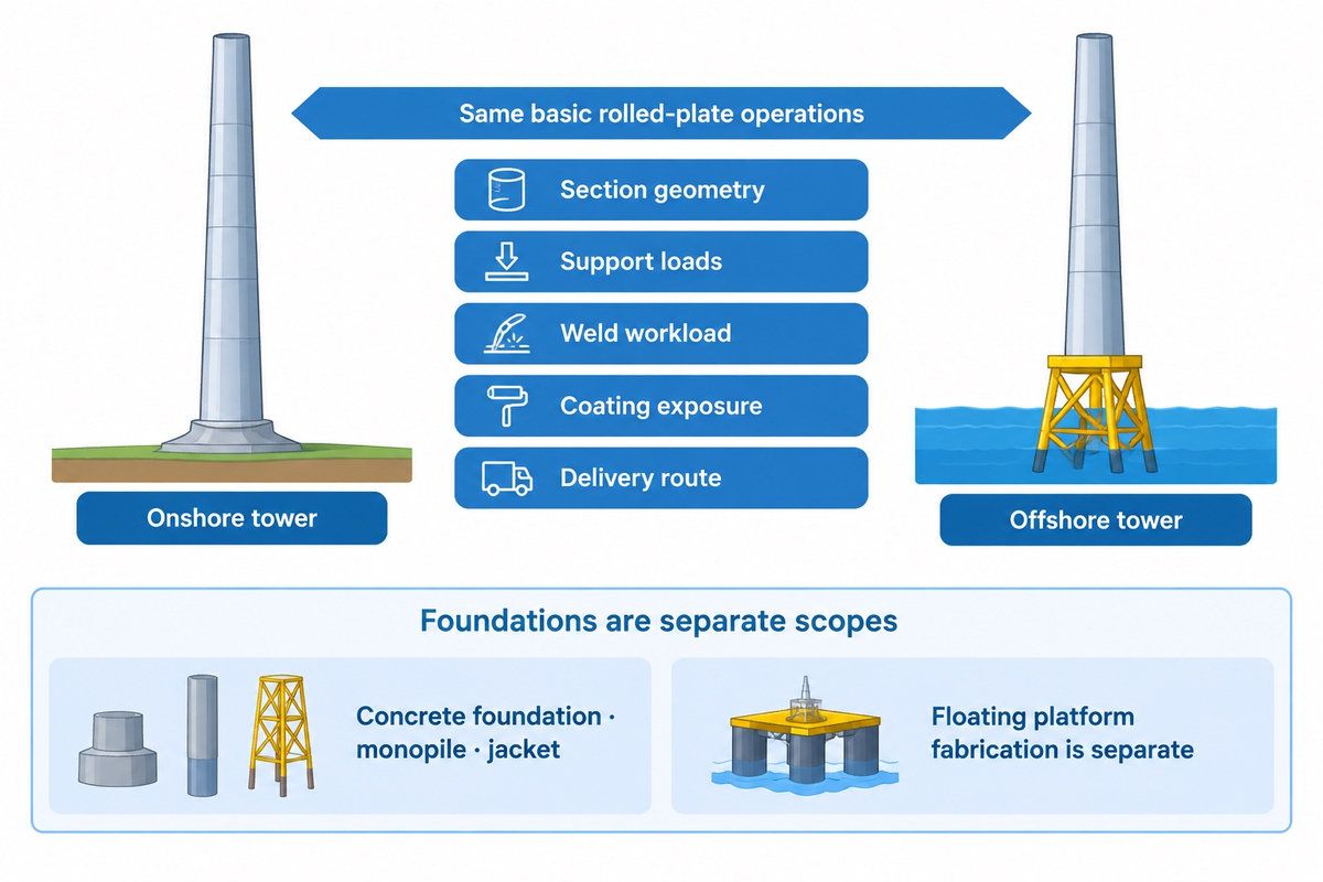
Onshore and offshore tower lines use the same basic rolled-plate operations, while section geometry, support loads, weld workload, coating exposure and delivery route change the equipment scope. Compare these physical requirements for the two project envelopes. Separate structures with different forming and handling requirements include the transition piece and a monopile foundation.
Towers are shell structures above the foundation interface. The tower and its support structures must be separated in the equipment list: a concrete foundation, a monopile and a jacket are not tower cans. Other tower constructions, including lattice and hybrid designs, also warrant a different process map rather than an expanded version of the rolled shell process.
For floating offshore projects, keep the tower-to-support interface distinct from fabrication of the floating platform. This guide covers the tower shell and factory transport sections; offshore installation interfaces and load-out belong in the project scope alongside the line layout.
The Department of Energy correlates increasing turbine scale to transport and logistical constraints, which means limits related to port access and load-out must be reviewed as part of the factory layout assessment. Wind turbine capacity in megawatts explains the generating machine; this isn’t a forming-machine rating or a substitute for the tower drawing.
Wind tower production line cost, lead time and suppliers
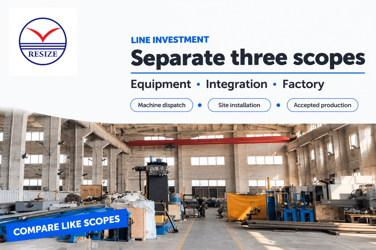
A comparable quotation separates three scopes: supplied machines, installed-line integration and whole-factory investment. Machines may be dispatched before mechanical installation; installation may finish before accepted production; accepted production may require trial sections, inspection records and operator training. Place each of the milestones on a commercial schedule.
| Scope | Include in the comparison | Questions to ask |
|---|---|---|
| Equipment package | Cutting, beveling, rolling, rotators, manipulators, welding and controls | What geometry, load and duty cycle are included? |
| Line integration | Layout, power, cranes, fixtures, safety, commissioning and training | Who supplies civil works and interface engineering? |
| Factory investment | Building changes, coating rooms, utilities, logistics and working capital | Which items are excluded from the machine quote? |
Broadwind’s filing for fiscal 2024 reports combined annual capacity of up to approximately 550 towers, or 1,650 sections, across two facilities. This is Broadwind’s nameplate capacity. A March 2023 New Mexico economic-development announcement describes Arcosa’s planned $55–60 million investment in property, plant modifications and equipment procurement. That historical facility budget covers a broader scope than a machine package.
For information on equipment, use the RESIZE production-line page. For controlled joint turning, where axial drift requires attention, use the anti-drift rotator page. Building wind turbines involves several supply chains; an equipment supplier and a finished-tower fabricator provide different purchasing scopes.
RESIZE supplies fabrication equipment. Broadwind and Arcosa are examples of finished steel-tower manufacturers in the cited factory records. A buyer building a tower factory needs the equipment and integration scope; a project buying finished tower sections needs the fabricator’s production scope and project acceptance requirements.
Quotation checklist for a tower line
Request a line-balance sheet showing the section mix, productive minutes, setup time, inspection holds, crane conflicts and rework allowance. Indicate the smallest and largest can sizes and final section mass. Clarify whether annual output is counted by cans, sections, or towers, and whether it’s nameplate capacity or accepted production.
Separate machine dispatch, site installation and acceptance of trial sections in the schedule. Record who supplies cranes, fixtures, utilities, civil works, coating rooms and operator training. Compare the manual loading and setup tasks of a CNC system with the staffing plan. Where rare heavy jobs drive the machine size, compare outsourcing those jobs with installing capacity that would otherwise stand idle.
What is changing in steel tower manufacturing
Taller turbines increase the importance of section geometry and transport planning. The Department of Energy reports average hub height of about 103.4 m for newly installed U.S. utility-scale land-based turbines in 2023. Hub height reaches the rotor center at the top of the tower; it differs from the tower’s structural height. Higher wind speeds at elevation help explain the drive for taller support structures.
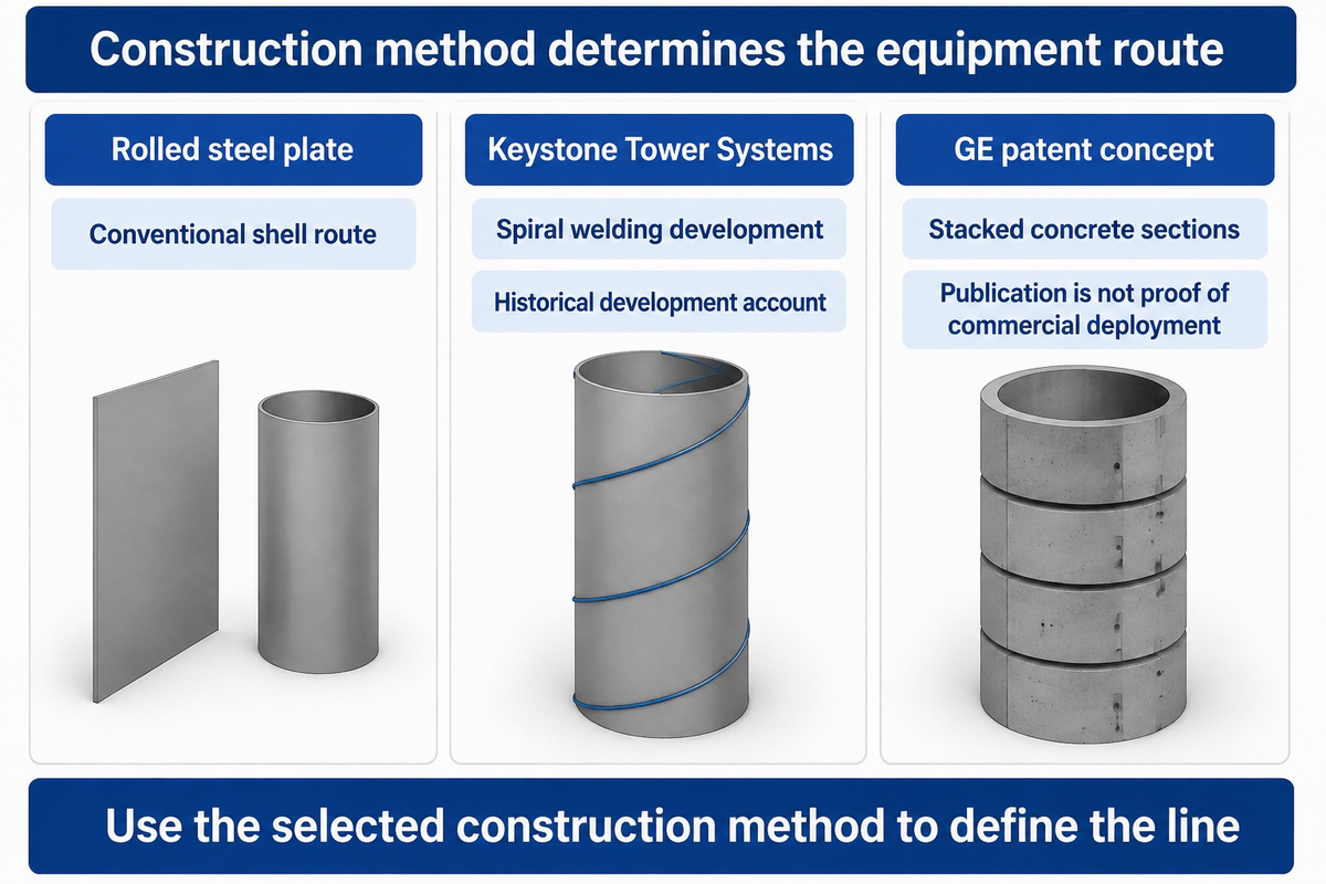
Alternative processes also change the equipment route. In May 2022, the Department of Energy described Keystone Tower Systems developing spiral welding for towers, with a first commercial installation expected later that year. Additive manufacturing appears in GE’s published stacked-section patent concept using concrete elements; it’s a different construction route from rolling steel plate, with General Electric Co listed as the applicant in the publication.
The fabrication process of wind turbine towers must therefore stay tied to the selected construction method. Modern wind projects require a route congruent to the structure being built; wind industry forecasts don’t replace the geometry and handling data used to size machines.
For the next capital review, model the expected product family and stress-test the bottleneck station, coating occupancy, crane path and dispatch route. Renewable energy demand explains the market; the accepted output and section drawing determine the line investment.
Frequently asked questions
What is the difference between a tower can and a tower section?
A can is one cylindrical or tapered shell closed by a longitudinal weld.
A transport section contains multiple cans joined by circumferential welds, usually with flanges and selected attachments. Several sections form the complete tower during erection. The number of cans per section depends on the drawing, so a rate stated in cans can’t be compared directly with a rate stated in sections. Ask the equipment supplier to use the same section family in every station calculation. Tower height alone doesn’t describe that family: can diameter, plate width, wall thickness and joint length also affect the manufacturing process.
Are wind tower joints welded or bolted?
Longitudinal and circumferential joints are welded during conventional factory fabrication; bolted flanges commonly join transport sections during erection.
The approved design controls the actual arrangement. Factory welding joins the edges of a rolled blank and then joins adjacent cans, while flange connections provide the planned interfaces between transport sections. A buyer should therefore specify both the weld workload and the section-end geometry. Including a welding station in the quotation doesn’t, by itself, cover the fixtures, flange measurements or site-assembly work needed for the complete tower.
Which inspections happen before tower coating?
Before coating, a section gets the weld examinations, dimensional checks and flange checks set by the inspection plan, plus re-examination of any repairs.
For a wind power project, connect each required check to its location in the factory route and the record that releases the section to the next station. The plan sets the examination method, extent and acceptance criteria. Repairs and subsequent examinations also need space in the schedule. Complete the specified pre-coating checks before the section enters surface preparation, and preserve its identification through coating and dispatch.
What limits wind tower production capacity?
The slowest accepted-output station limits the line. Rolling, welding, cranes, inspection, blasting, coating, cure time, rework and dispatch can each become the bottleneck. Use one work unit, such as accepted transport sections per shift, when comparing stations.
What should a wind tower production-line quotation include?
Ask for the equipment list, geometry envelope, load assumptions, utilities, layout, cranes, safety interfaces, commissioning, training, spares and acceptance test. Separate dispatch, installation and accepted production dates. Ask which civil, coating and logistics items are excluded.
Send the target can and section geometry, material range, joint process, handling loads, shift plan and coating route. RESIZE can then discuss the relevant wind tower production-line equipment, welding manipulators, welding rotators en beveling equipment as a defined scope.
References & Sources
- U.S. Department of Energy: Explore Wind Turbine (text version) provides context for the tubular steel tower and section assembly.
- U.S. Department of Energy: Wind Turbines: Bigger and Better provides context for the hub-height trend.
- U.S. Department of Energy: Wind Manufacturing and Supply Chain explores challenges related to distribution and logistics.
- The Fabricator: Rolling for Wind rolling time versus full-cycle time.
- The Fabricator: Automation Consultation for Wind Tower Masts describes fit-up and circumferential welding.
- International Organization for Standardization: ISO 3834-2:2021, public welding-quality scope.
- Broadwind 2024 Form 10-K includes disclosure of nameplate capacity for two facilities.
- New Mexico Economic Development Department: wind-tower expansion announcement gives historical project investment scope.
- The Fabricator: The Big Challenge of Wind Energy Component Fabrication describes plate guidance and weld preparation.
- U.S. Department of Energy: spiral welding development account (May 2022).
- GE patent publication EP4361380A2, stacked tower-section concept; publication is not evidence of commercial deployment.