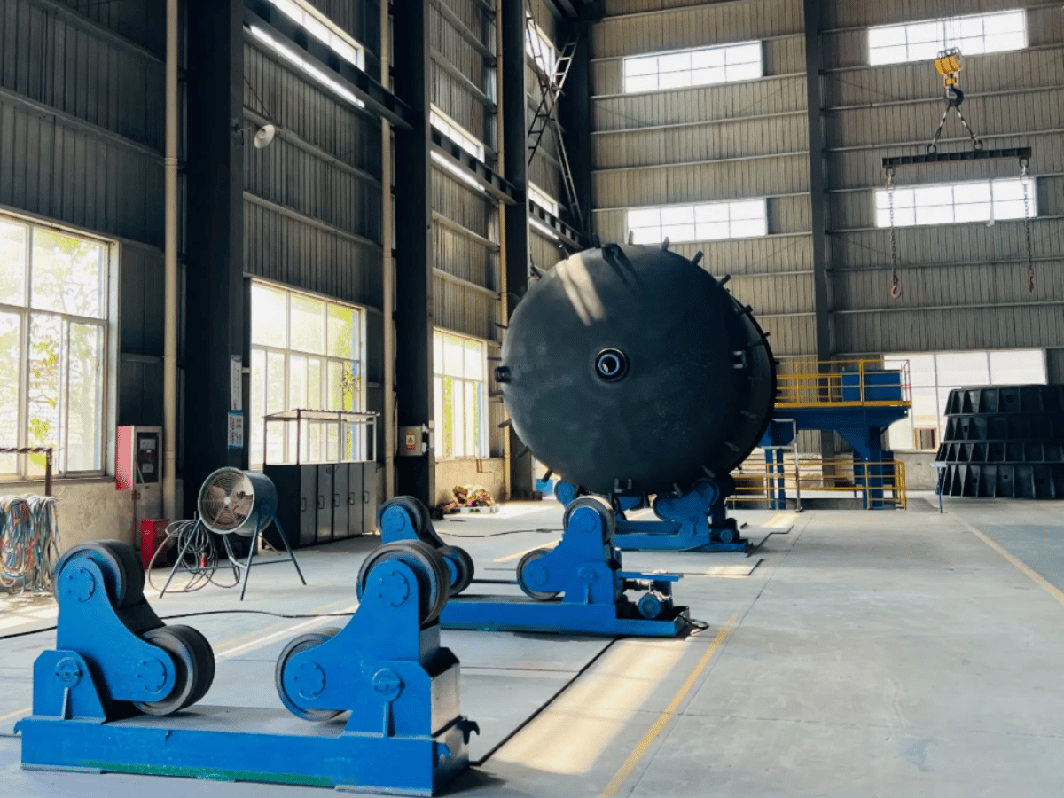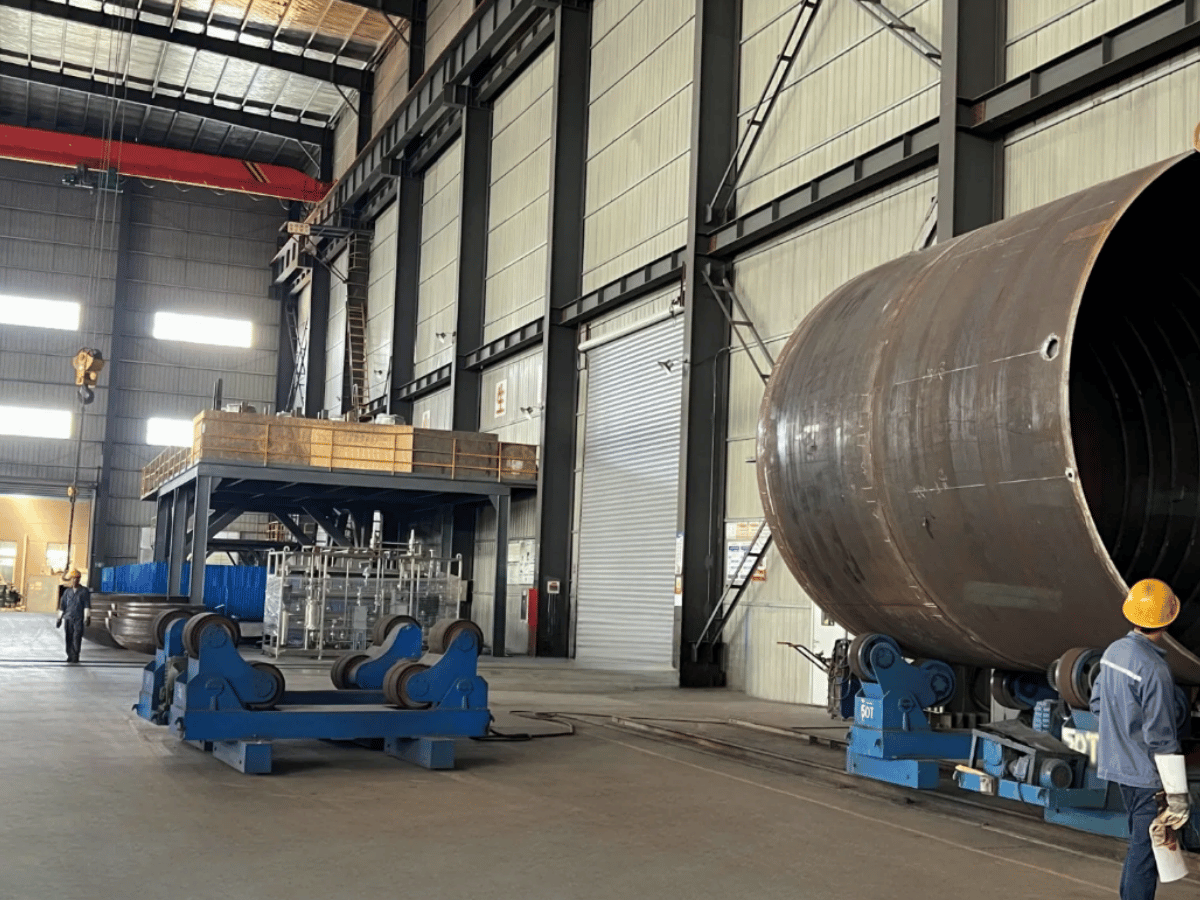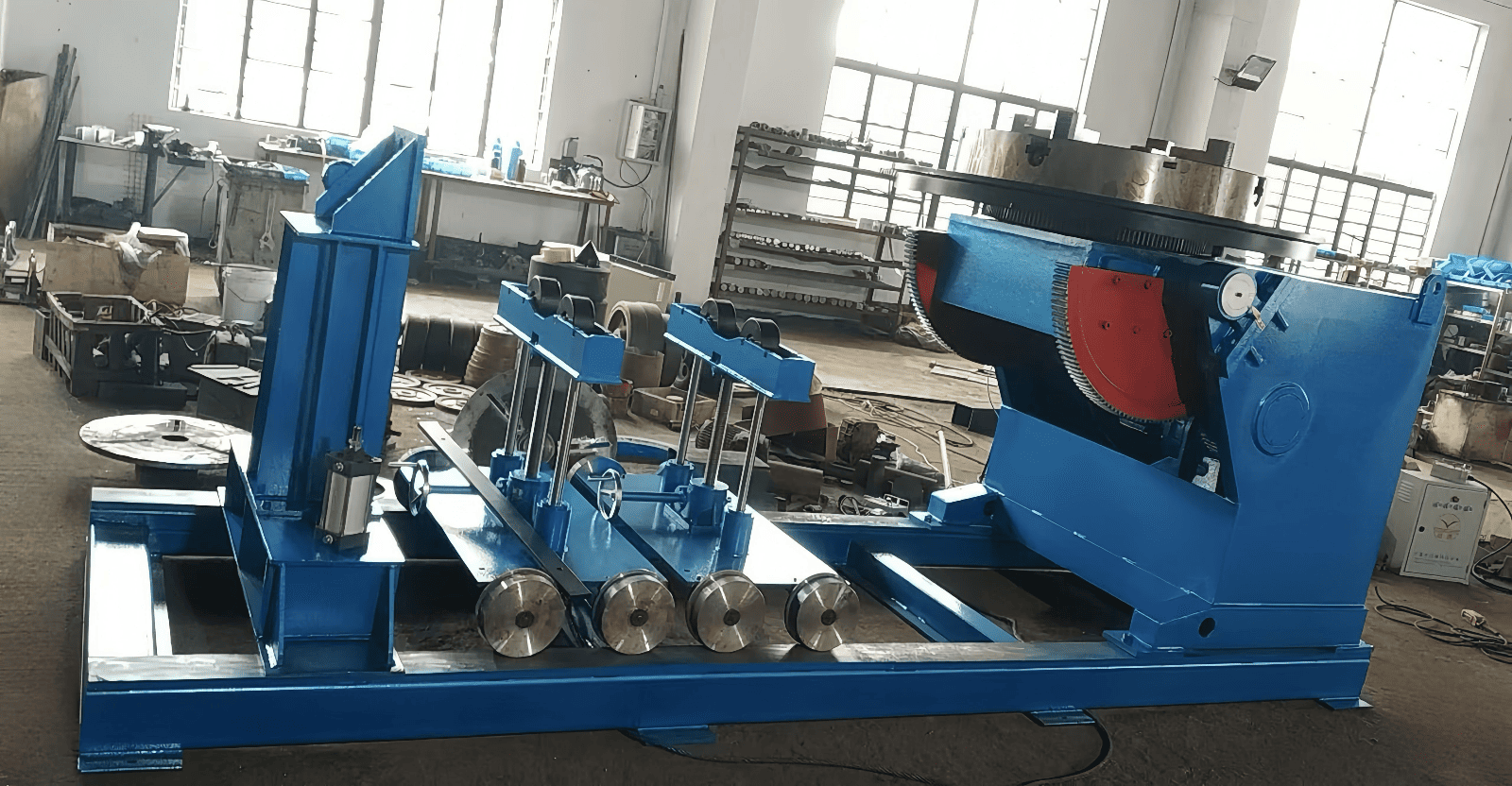
Depending on the assembly, welding equipment for shipbuilding should include panel stations for long accessible seams, portable equipment for hull blocks and controlled rotation for suitable pipe spools. The welding process is then matched to the joint and approved procedure; the support and torch motion are sized and access around the loaded workpiece is considered.
A power supply is only a part of that purchase. The needs of the shipbuilding industry extend to fixtures, handling, extraction and handoff to inspection. Each determines if a faster weld results in an accepted assembly. The comparisons separate these responsibilities so that production, quality and purchasing can assess the same work center.
Updated November 2026 · Published by RESIZE
Match the Equipment to the Shipyard Workpiece
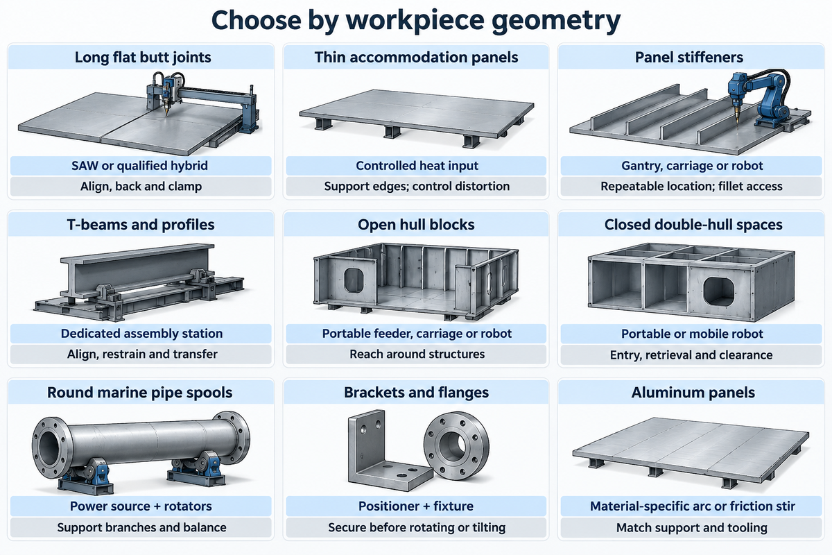
Round assemblies suit equipment that turns the part, and flat assemblies suit equipment that carries a torch along a supported joint. Open blocks need access around stiffeners, and closed blocks add a path access problem. Start the shipbuilding process selection with workpiece geometry, position of welding and the path into and out of the station.
| Workpiece or task | Equipment starting point | Motion and support to specify |
|---|---|---|
| Long flat plate butt joints | Submerged arc or qualified hybrid panel station | Travelling head; plate alignment, backing and clamping |
| Thin accommodation panels | Controlled-heat-input panel system | Supported steel plates; edge preparation and distortion control |
| Stiffeners on flat panels | Gantry, carriage or suitable robot | Head follows fillets; locate each stiffener repeatably |
| T-beams and built-up profiles | Dedicated assembly and welding station | Profile alignment, restraint and transfer between operations |
| Open hull blocks | Portable wire feeder, carriage or robot | Reach around bulkheads and ship structures without blocking access |
| Closed double-hull spaces | Portable equipment or purpose-designed mobile robot | Check entry dimensions, retrieval route and working clearance |
| Round marine pipe spools | Power source and welding rotators | Turn the supported spool; account for branches and changing balance |
| Small brackets and flange assemblies | Suitable laspositioneerder and fixture | Rotate or tilt a positively secured assembly |
| Aluminum panel assemblies | Material-specific arc or friction-stir system | Match joint support and process tooling to the aluminum design |
Thin ship construction changes the trade off. In a 2009 study of 4 mm DH36 butt joints, laser and laser hybrid welding produced the least distortion among the processes compared. Pulsed gas metal arc welding and cold metal transfer also produced better results. The lesson is to compare processes on the intended material and joint with distortion among the acceptance criteria.
Picture a yard moving a bulkhead panel from loose plates to a stiffened assembly. A straight seam can be accessed prior to stiffener installation. Later, the same torch can collide with framing, and the completed panel requires a different lifting arrangement. Consequently, production requires trials at the actual assembly stage. Also, marine engineering needs dimensional checks following the welding sequence since a panel that leaves the station quickly can still delay block fit-up. The purchasing brief should indicate which joints are completed prior to assembly closing access and who supplies the transfer equipment.
What equipment do you need for welding?
A shipyard welding station requires a compatible power source, torch or electrode holder, work-return connection, workpiece support, and process-specific consumables. Wire-fed welding requires a feeder; gas-shielded welding requires a suitable gas supply. Extraction, screens, and personal protective equipment belong in the station plan, as do the welding tools.
Choose the Welding Process for the Joint and Position
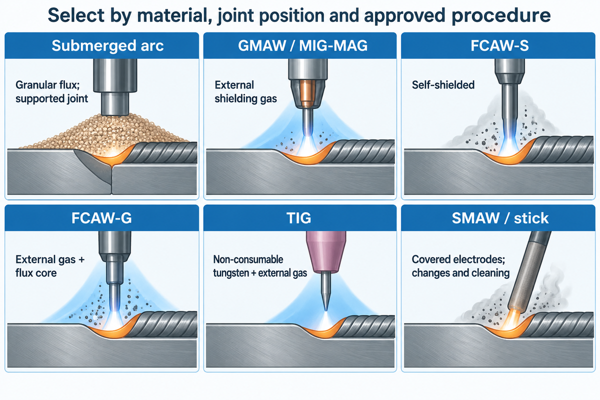
Submerged arc welding fits accessible joints where the flux and weld pool can be supported. Wire-fed processes offer flexibility around ship components. TIG and stick welding serve different access needs. Select the process based on the material, joint position and welding procedure specification before choosing the equipment that moves it.
Submerged arc welding: a continuously fed electrode works beneath granular flux. Long, repeatable seams in large steel plates make a good starting case. The public scope of ISO 9692-2:2024 joint preparation covers single-wire submerged arc welding of steel in PA and PB positions; PC requires special preparation.
GMAW and MIG/MAG: gas metal arc welding employs an externally supplied shielding gas. The choice of gas, filler, and alloy combination matters when selecting among these welding methods. Pulsed variants can help manage heat input, but the procedure still governs the joint. High welding speeds that leave an unacceptable profile or lack of fusion create a repair.
Flux-cored arc welding: This process distinguishes self-shielded FCAW-S from gas-shielded FCAW-G. According to the American Welding Society’s FCAW explanation, FCAW-G uses external gas in conjunction with the flux core. Slag removal and fume control remain part of the process plan. A gasless claim can’t be generalized to all flux-cored wires.
TIG welding: Gas tungsten arc welding employs a non-consumable tungsten electrode and external gas to shield the weld area. This process is used for joint control rather than to match the deposition behavior of a wire-fed production station. SMAW: shielded metal arc welding, or stick welding, uses individual covered electrodes; electrode changes and cleaning belong in its cycle comparison.
There are specific considerations for hybrid systems that warrant a separate trial. The study of hull-plate butt joints published by the Japan Welding Society notes investment and gap-tolerance trade-offs for laser-arc hybrid welding systems. Less distortion of the workpiece is valuable only when the yard can prepare and hold the joint within the chosen process window. Resistance welding and gas welding are different process scopes from the arc-welding stations considered here; a quote should indicate which type of welding it actually supplies.
Consider a supported welding position for a long, repeatable plate joint. Place submerged arc welding before flux-cored welding in the station trial. With restricted access or work in different positions, consider appropriate flux-cored wires against the qualified procedure. These various welding techniques need different support, shielding and cleaning arrangements; deposition rate alone does not settle the choice.
The welding techniques used must also match the alloy and the intended marine environment. Corrosion resistance, weld quality and the structural integrity of ships depend on the material, joint design and qualified production controls. Ship design defines the material and joint requirements; a more powerful welding machine doesn’t change the approved filler, joint preparation, or inspection requirements.
Size the Station Around Reach, Load and Access
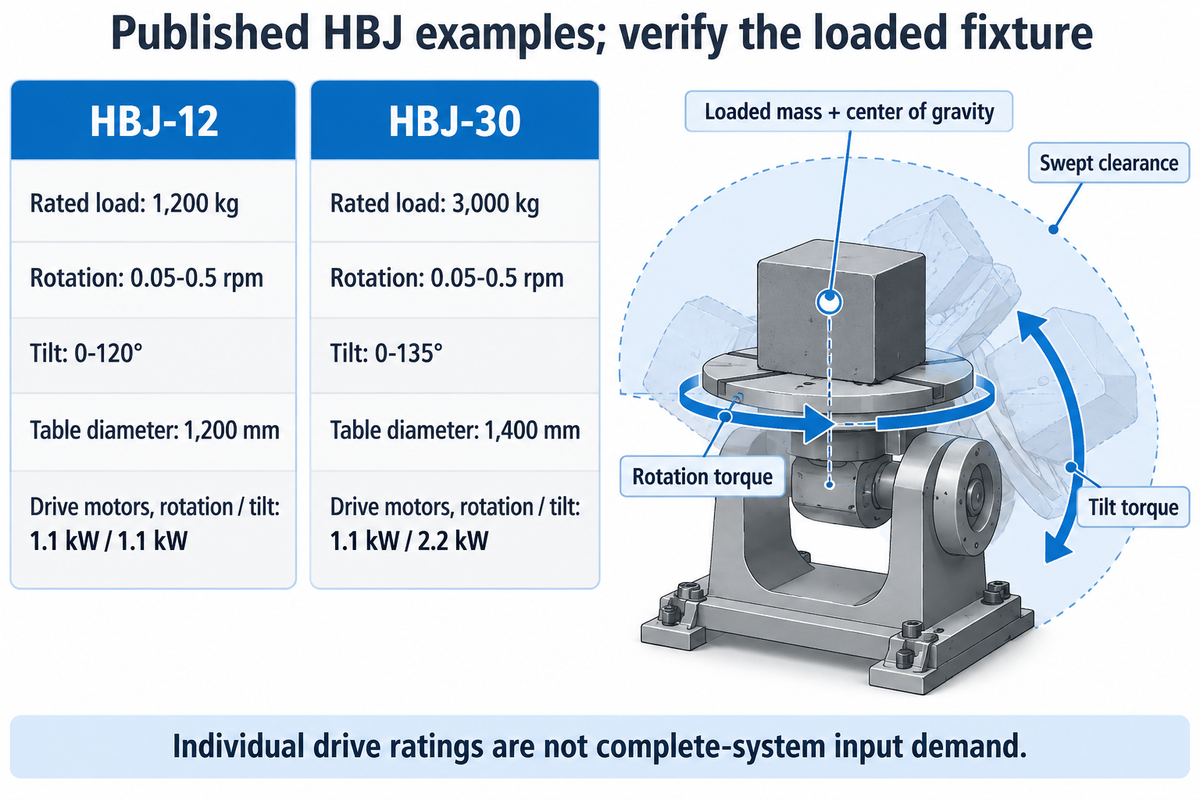
RESIZE lists the HBJ-12 at 1,200 kg and the HBJ-30 at 3,000 kg, with different tilt ranges and table sizes. Use these model values to identify a positioner, and then submit the loaded fixture drawing. The mass, center of gravity, rotation torque, tilt torque and swept clearance must all relate to the same assembly.
| Model | Rated load | Rotation | Tilt angle | Table diameter | Drive motors: rotation / tilt |
|---|---|---|---|---|---|
| HBJ-12 | 1,200 kg | 0.05–0.5 rpm | 0–120° | 1,200 mm | 1.1 kW / 1.1 kW |
| HBJ-30 | 3,000 kg | 0.05–0.5 rpm | 0–135° | 1,400 mm | 1.1 kW / 2.2 kW |
Each motor entry describes an individual drive. Neither motor rating sizes the input demand of complete welding systems. A table’s rotational travel and its tilt angle are different motions; stating “360-degree positioning” doesn’t clarify required tilt.
Think about a flange assembly that fits within a catalog load rating. Adding a tall fixture lifts the center of gravity, while a branch connection offsets it from the rotation axis. Both motions face different moments, although the mass may barely change. Koike’s HD400 sizing example illustrates the rating condition: 40,000 lb at a center of gravity 12 in from the table. Its selection method considers tilt and rotation moments separately. Submit the fixture mass and geometry with the part drawing, then check the full sweep for interference with the floor, torch and supporting structure.
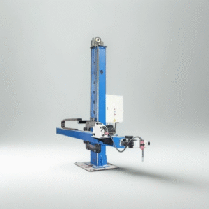
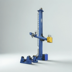
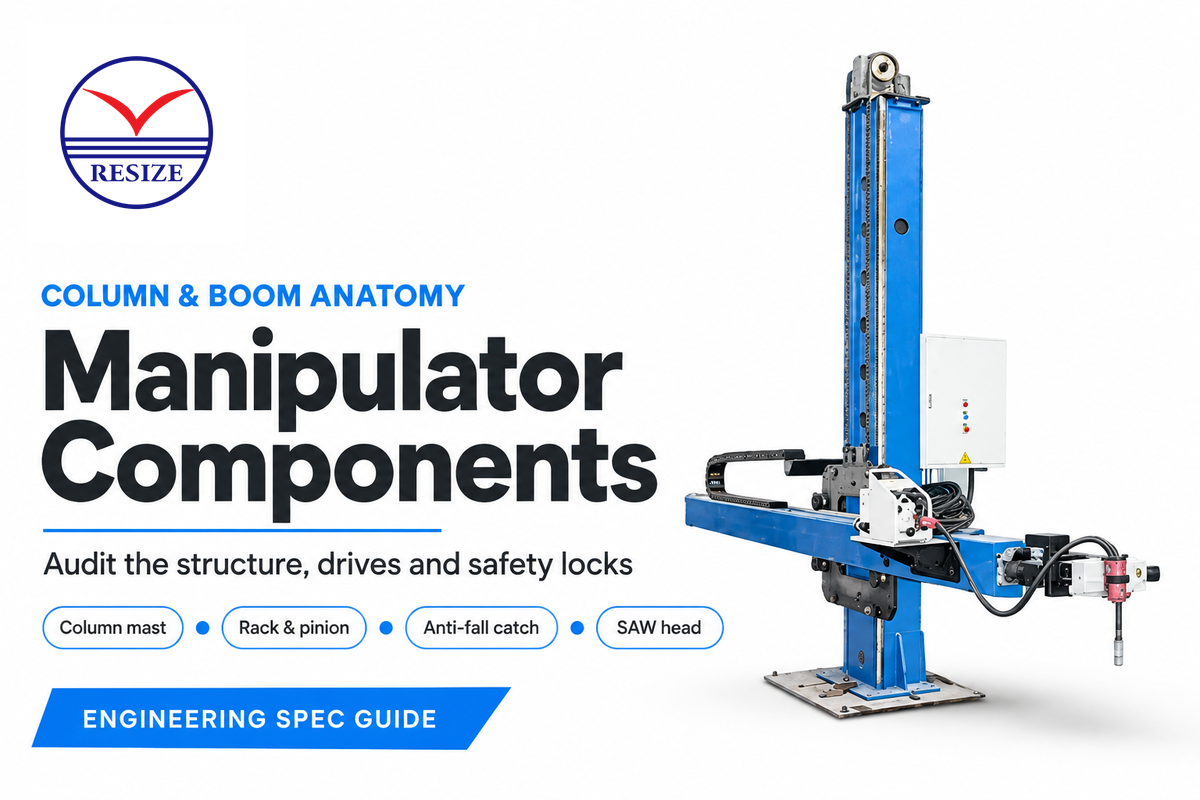
A column-and-boom welding manipulator moves the head instead. RESIZE’s pipe-family page lists horizontal and vertical travel up to 8,000 mm. The head, feeder and accessories must be matched to the supported load at the required extension. Our column-and-boom sizing guide develops that reach-and-load brief.
Entry geometry can be tighter than working reach. A 2007 Rail Runner research prototype was designed to pass through a 600 mm-wide, 800 mm-high opening. Those are prototype dimensions, not a standard ship opening. Map the equipment’s route, alongside the personnel access and duct arrangements addressed by OSHA’s shipyard access requirements.
How do pipe welding rotators support marine spools?
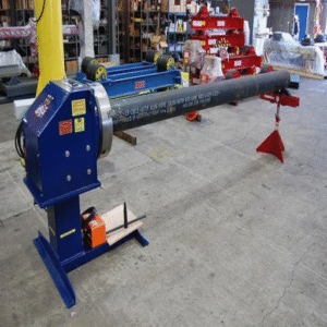
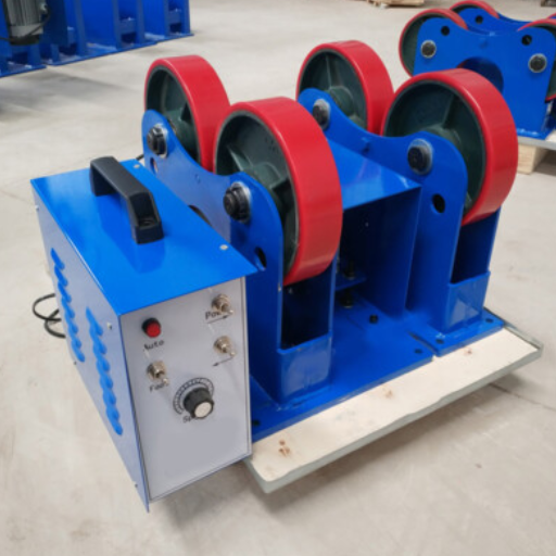
Rotators support round sections on rollers and turn the workpiece past the welding head. RESIZE offers self-aligning units with a linear speed of 6-60 m/h. Branches, flanges and changing balance affect the support arrangement. Selection for pipe welding is explained in the pipe rotators for welding guide.
Test Productivity Beyond Arc Time
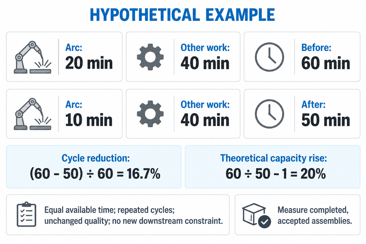
In an assumed 60-minute cycle containing 20 minutes of arc time, halving arc time cuts the cycle to 50 minutes if all other work stays fixed. The cycle becomes 16.7% shorter; theoretical cycle capacity rises 20%. Measure completed, accepted assemblies before treating either result as a shipyard productivity gain.
Weld-to-Move Test
The Weld-to-Move Test covers loading through release of an accepted assembly, with welding and non-welding time recorded separately.
The arithmetic says 10 + 40 = 50 minutes after the change. Cycle reduction is (60 – 50) ÷ 60; capacity change is 60 ÷ 50 – 1. In the interest of simplicity, we’ll assume equal available production time, repeated cycles, unchanged quality and no new downstream constraints. Parallel operations, downtime and rejected pieces require a fuller production model.
| Where time goes | Record | Decision owner |
|---|---|---|
| Loading and crane wait | Elapsed minutes before clamping starts | Production: handling arrangement |
| Fit-up and preparation | Setup minutes and joint variation | Welding engineering: preparation method |
| Programming and repositioning | Changeover time for the next assembly | Production: automation scope |
| Arc-on work and cleaning | Separate welding and interpass work | Welding engineering: process choice |
| Inspection and correction | Accepted dimensions, repairs and correction time | Quality: acceptance condition |
| Release and transfer | Time until the next station can receive the part | Production and finance: usable output |
An Oak Ridge National Laboratory 2023 research abstract connects deformation, welding sequence and fixturing with fitting and rework labor. Dimensional acceptance therefore belongs in the trial alongside weld inspection. Faster welding offers very little scheduling benefit if the time saved is consumed by additional correction.
For robotic welding, include awkward joints and changeovers currently handled by skilled welders. Seam tracking for welding can address some variation in selected joint locations; however, an adaptive welding system would need a suitable joint and a torch path that’s traversable. Evaluate the accepted output of the entire route to determine how much to automate.
Compare Complete Station Costs and Handoffs
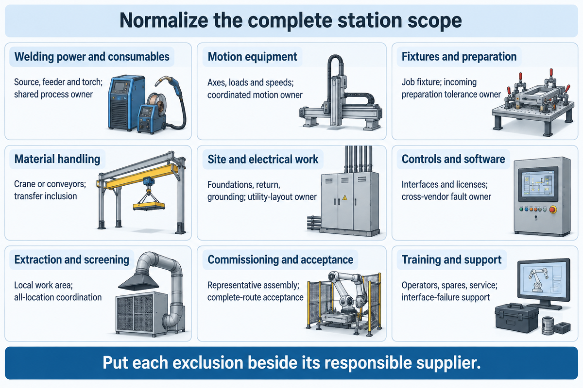
Compare stations on an equal basis using the delivered scope: welding package, motion, fixtures, handling, site connections, controls, extraction, commissioning and support. Separate supplier charges from work the yard must purchase elsewhere. Finance needs installed cost and an accepted output trial to estimate the value of an equipment replacement proposal.
“Will training/retraining be necessary to be able to use the equipment safely?”
| Package | Standalone station question | Integrated-line question |
|---|---|---|
| Welding power and consumables | Which source, feeder and torch are included? | Who qualifies their shared process package? |
| Motion equipment | Which axes, load conditions and speeds? | Who coordinates motion across stations? |
| Fixtures and preparation | Who supplies the job-specific fixture? | Who holds incoming preparation tolerances? |
| Material handling | Does the yard crane load and unload? | Are conveyors, buffers and transfers included? |
| Site and electrical work | Who supplies foundations, return circuit and grounding? | Who owns combined utility and floor-layout design? |
| Controls and software | Which interfaces and licenses are supplied? | Who resolves cross-vendor control faults? |
| Extraction and screening | How is the local work area served? | Who coordinates extraction with all work locations? |
| Commissioning and acceptance | Which representative assembly is tested? | Which complete route and output are accepted? |
| Training and support | Which operators, spares and service are covered? | Who supports the line after an interface failure? |
Suppose purchasing compares a positioner quote with an automated welding cell. The lower figure may cover only the mechanical unit, while the cell includes a power package and coordinated controls. Production needs its fixtures and handling included in the comparison; quality needs an agreed test assembly; finance needs the cost of yard-supplied installation and downtime during commissioning. Put each excluded item beside its responsible supplier. Once both offers describe the same usable station, the difference in acquisition cost becomes meaningful, and the cycle trial can inform the capacity decision.
A welding panel-line system adds transfer, alignment and coordinated station controls to the scope of a standalone power source or positioner. Obtain project quotes for the packages and estimate labor impact from measured activity time. Equipment that releases welding labor may shift work into programming, preparation, or inspection rather than eliminate it.
Which Suppliers Fit Each Equipment Scope?
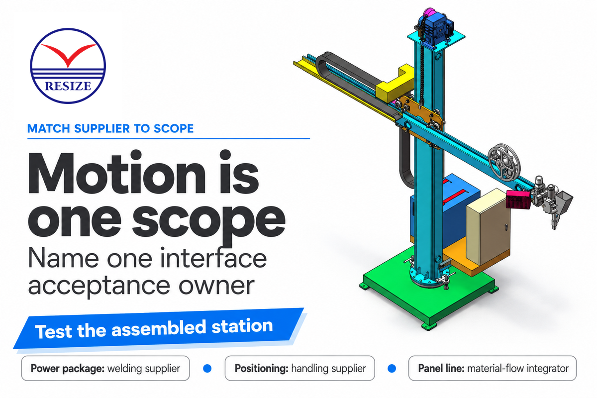
Send a power-package inquiry to a welding equipment supplier, a positioning inquiry to a handling equipment supplier, and a panel-line inquiry to an integrator who owns the entire material flow. These systems should be evaluated in combination. Comparing them as interchangeable products conceals who will connect, commission, and support the complete workstation.
RESIZE supplies welding positioners, rotators and manipulators for workpiece support and controlled motion. Miller’s shipyard material covers point-of-use welding control. Pemamek’s 2020 Babcock announcement covers thin-plate, micro-panel and T-beam lines. Kranendonk’s 2025 event showcased mobile robotic welding and pipe-shop automation.
If the yard already owns ESAB or Miller welding machines, identify the exact models and required control interface before requesting new motion equipment. The NIST purchasing guide’s connection and training questions are relevant here: who integrates the existing equipment and who trains the people operating the integrated system?
For shipbuilding projects that combine multiple suppliers, name a single party responsible for interface acceptance testing. Mechanical delivery and power-source tests leave coordinated welding operations untested unless the assembled station also processes the agreed workpiece. Invite the people who operate welding equipment to take part: their welding experience can identify deficiencies in controls, loading and access during the test.
Use this order to transform the assembly requirement into a comparable purchasing package for a shipbuilding and marine equipment inquiry.
- Define the assembly — provide its material, joints, loaded fixture and access route.
- Agree the trial — specify representative welding using the intended procedure, then inspection and release criteria.
- Assign the interfaces — identify who supplies handling, utilities, controls and training.
- Compare complete offers — reconcile exclusions before comparing installed cost and accepted output.
Industry Outlook: Integration and Utility Requirements
Projects scheduled around 1 January 2027 should settle the applicable welding qualification requirements before ordering a new station: IACS lists that date for W28 Revision 3 to enter into force. Match the contract’s procedure and personnel requirements to the process, then assign responsibility for electrical, extraction, access and commissioning activities before the equipment is installed.
The IACS W28 version page concerns procedure qualification for steel hull construction and marine structures. ISO 14732:2025 addresses operators and setters for mechanized and automatic welding, with exclusions for personnel who do not control parameters or set up equipment. Name the applicable industry standards in the purchasing brief and define the process and operating roles; an equipment badge does not supply the project’s qualification package.
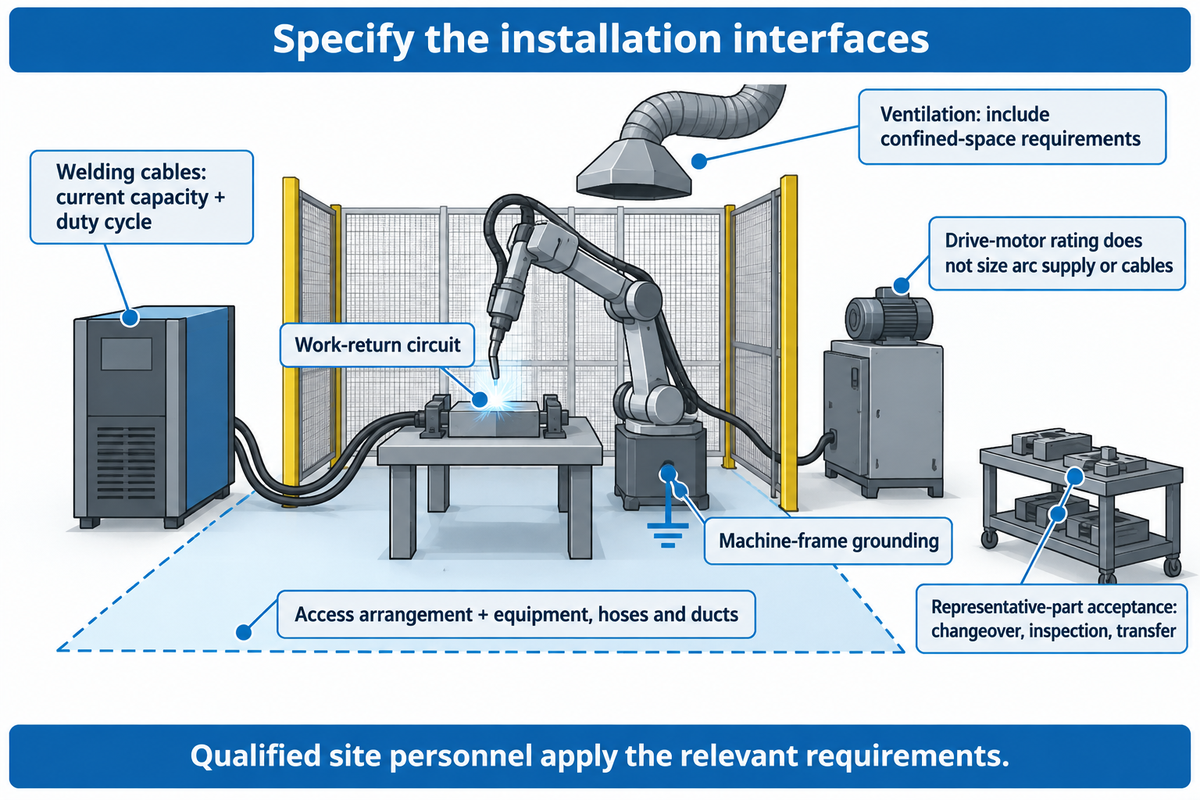
Welding technology in modern shipbuilding also alters utility lines. For the marine industry, welding is also an electrical installation task; OSHA 1915.56 addresses welding cable current capacity and duty cycle, the work-return circuit, and machine-frame grounding separately. Define those interfaces in the installation task. A positioner’s drive-motor rating does not size the arc-welding supply or its cables.
OSHA 1915.51 stipulates certain ventilation requirements, including provisions for confined spaces in shipyards. Equipment, hoses and ducts must fit the access arrangement as well as the floor plan. The yard’s qualified personnel must apply the relevant safety standards and site safety protocols to that layout.
Portable robots and CAD-linked production can change where preparation and programming happen. Kranendonk’s 2025 demonstrations featured mobile robotic welding and pipe-shop automation. Use the same representative-part acceptance test for advanced welding systems as for simpler stations, including changeover, inspection and transfer. The ISO 3834-2 welding requirements guide provides related context for adherence to quality requirements across those responsibilities.
Shipbuilding Welding Equipment FAQ
What type of steel is used for shipbuilding?
Shipbuilding uses classed hull structural steels: class rules separate normal-strength grades A, B, D and E from higher-strength grades such as DH36, with a 355 MPa minimum yield stress, chosen for the vessel’s structure, service and classification requirements.
Start with the approved material and joint specification. Hull plates and structural members may require different strength, toughness and thickness choices. The power source alone doesn’t select the steel. Match the filler and welding procedure to the actual material, then include the required inspection and traceability in the production plan.
How is maritime welding different from general fabrication?
Welding marine vessels combines structural and service requirements with difficult access, large assemblies and vessel-specific production controls.
A shipyard may weld flat panels in a controlled workshop and later work inside assembled blocks. That change affects handling, ventilation and torch access. The welding used in shipbuilding must follow the applicable procedure and inspection plan, while watertight construction and the marine environment make joint quality and material selection central to the project.
Can welding machines be used on deck?
Yes, when the equipment and the yard’s approved work arrangements suit the deck location and conditions.
Confirm the machine’s environmental suitability, electrical connections, cable route and protection of nearby people. Deck location alone doesn’t settle hot-work permission. OSHA 1915.14 distinguishes testing and certification requirements for specified spaces and adjacent areas, with exceptions. The yard must meet the applicable requirements before welding and cutting begin.
Can a positioner replace turning rolls?
Only for assemblies that a fixture can secure to the table within its load chart, such as small brackets and flange assemblies. A positioner secures a part to a table for rotation or tilt; turning rolls support suitable cylindrical surfaces. Compare the actual support geometry and required motion.
What equipment is needed to remove a welded fitting from a ship’s deck?
The removal plan may require suitable cutting or gouging equipment, support for the released fitting, extraction and inspection equipment.
Selection starts with the fitting, deck material and permitted removal method. A crew can’t simply gouge through a connection without addressing what the fitting supports or what lies behind the deck. The yard’s authorized personnel must define the sequence, hot-work controls and final condition of the remaining structure before choosing the welding and fabrication equipment for the job.
Are self-shielded and gas-shielded flux-core wires interchangeable?
No. Their shielding requirements differ, and substitution must follow the wire specifications and approved welding procedure. Buying flux-cored wire doesn’t by itself remove the need for an external gas supply.
What should a shipyard include in a welding-equipment inquiry?
Include a representative assembly drawing, material and joint details, the welding procedure, required motion and expected production mix.
Add loaded mass with fixtures, center-of-gravity information, entry and swept clearances, available utilities and the planned acceptance test. Identify existing equipment that must connect to the new station. Separate the supplier’s scope from yard-supplied handling, site work and extraction. Those inputs let suppliers propose a defined station and explain the remaining engineering decisions before a final order.
Select the station around a real assembly, then compare accepted output from loading through release. Match the welding process, loaded motion envelope and supplier interfaces before comparing the purchase price.
Designing a round-part station or fixture-based assembly cell? Send RESIZE your welding-equipment inquiry with the part drawing, loaded mass and required motion. We can discuss the scope of positioners, rotators and manipulators while your project team defines the welding procedure and acceptance requirements for the shipyard installation.
Source note: This guide merges public product specifications, published research, and official standards summaries. The cycle calculation is a hypothetical example, not a measured result for a RESIZE customer.
References & Sources
- Lund University research record, Welding process impact on residual stress and distortion
- ISO 9692-2:2024, Joint preparation for submerged arc welding of steels
- American Welding Society, Flux-cored arc welding principles and applications
- Japan Welding Society (publisher), Laser-arc hybrid welding of thick plate butt joints
- Acta Press, Rail Runner welding-robot research abstract
- OSHA 1915.76, Access to cargo spaces and confined spaces
- Oak Ridge National Laboratory, Welding-sequence analysis research
- NIST, Manufacturers: Pre-Purchase Guide for Equipment
- IACS W28, Procedure qualification and revision status
- ISO 14732:2025, Qualification of welding operators and setters
- OSHA 1915.56, Arc welding and cutting
- OSHA 1915.51, Ventilation and protection in welding, cutting and heating
- OSHA 1915.14, Hot-work testing and certification conditions