Updated August 2026
Plasma cutter settings are not a universal recipe. Thickness narrows the starting point, but the power source, plasma torch, installed consumables, air system, and cutting mode determine the actual amperage, speed, and pressure. Choose the correct manual row, then verify it with one controlled cut on representative material.
Plasma cutter settings start with the exact machine and consumable cut chart. Check pressure under flow, then validate amperage, speed, and height with one controlled test cut.
- Exact values: machine manual and installed-consumable chart
- Pressure check: gas flowing, not idle gauge only
- Calibration: one variable per test cut
- Modes: keep handheld and CNC settings separate
- Acceptance: define penetration, dross, roughness, heat input, productivity, and consumable life
- Current can be the controlling variable when it’s too low to penetrate.
- No cross-brand PSI value is universally defensible.
- A rated cut and a sever cut aren’t the same acceptance condition.
- CNC settings add height, delay, voltage, and motion controls.
Make the First Test Cut Fire-Safe
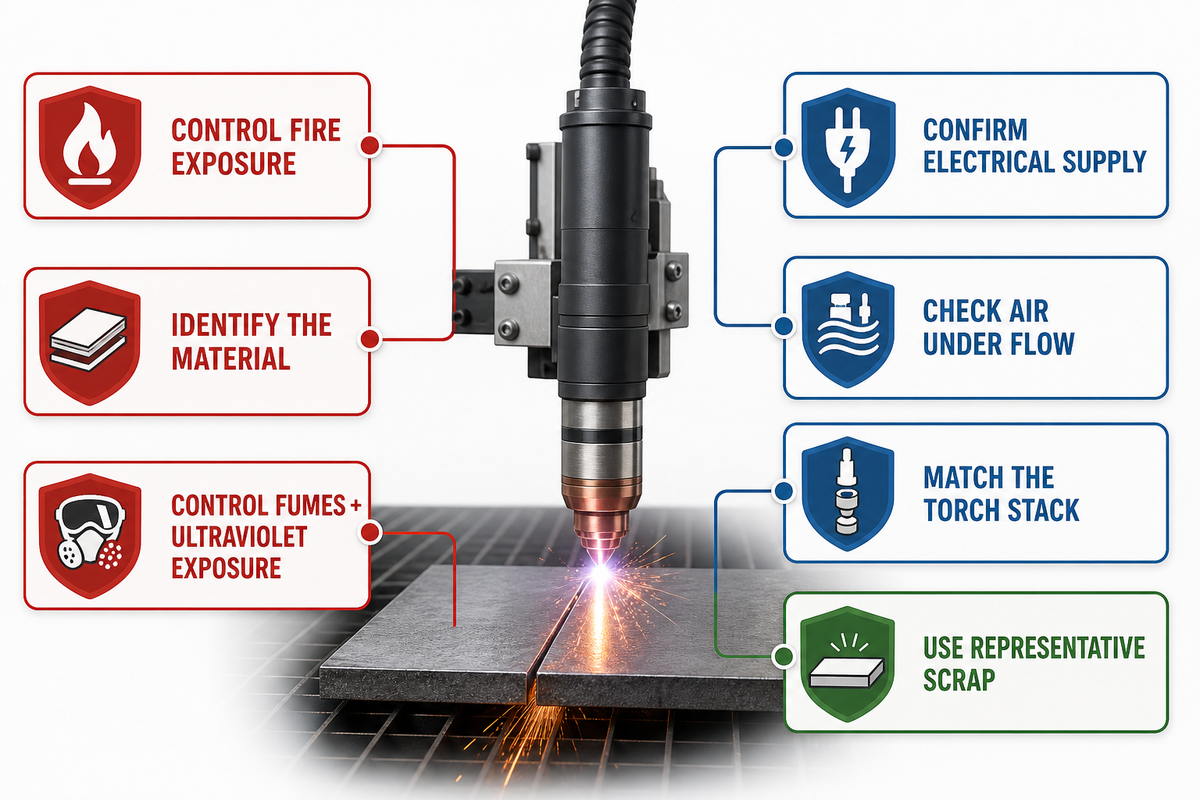
Settings become useful only after the work is safe and the process is stable. Damp air, a loose work lead, damaged consumables, or coated metal make the test uncontrolled. That failed cut doesn’t prove one setting is wrong.
Personal protection matters throughout the cutting process. Welders need a welding helmet or approved face shield that protects against ultraviolet light at the actual current, plus suitable skin, clothing, and fume controls.
- Control fire exposure. Move combustibles away from sparks and hot slag, protect anything that can’t be moved, and provide the fire-prevention measures required for the work area.
- Identify the material. Confirm the alloy, coating, plating, paint, oil, or residue before cutting. Fume composition changes with the material, so controls suitable for clean mild steel may not be adequate for another alloy or coating.
- Control fumes and ultraviolet exposure. Use suitable general or local exhaust, keep your head out of the plume, and follow the applicable respiratory, face, eye, skin, and clothing requirements.
- Electrical supply – confirm the correct voltage and protective ground. Check work-lead contact, cable condition, and installation against the manufacturer’s directions.
- Air supply – drain moisture from the air line, check filters and hoses, and check the specified pressure or gas-test mode while the system is flowing.
- Torch stack assembly – fit the correct electrode, nozzle, swirl ring, shield, cap, and current rating. Replace damaged parts before tuning.
- Use representative scrap. Test on the same material, thickness, surface condition, and orientation as the production part.
OSHA’s hot-work rule treats specially designated fire-safe areas as the preferred location for cutting.
What darkness setting should you use for plasma cutting?
Use the filter-lens shade required for the actual cutting current and process, then increase protection if the arc is uncomfortable to view. Don’t copy an oxy-fuel shade or assume one shade fits every amperage. Consult the current equipment manual, the applicable eye-protection table, and your safety program; ordinary sunglasses aren’t protective equipment.
Match the Chart to Your Machine, Torch, and Consumables
Two “60 A” cutters may need different rows because rated current is only one process variable. Results also depend on torch design, nozzle orifice, shield, gas mode, duty cycle, arc voltage, height control, and the manufacturer’s definition of rated cut. An older 2018 university reference shows very different currents for three plasma-system categories cutting the same nominal 16 mm mild steel. Its values aren’t current operating guidance; they show why thickness can’t be the only input.
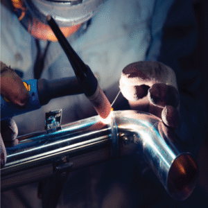
The plasma arc is forced through a cutting tip. When a welder moves from a weld joint to a plasma cut, the exact torch-and-consumable geometry affects which chart row applies.
| Older 16 mm mild-steel example | Current | Speed | Permitted use here |
|---|---|---|---|
| Dual-gas system | 150 A | 1.9 m/min | Counterexample only |
| Water system | 400 A | 2.1 m/min | Counterexample only |
| Air system | 250 A | 1.9 m/min | Counterexample only |
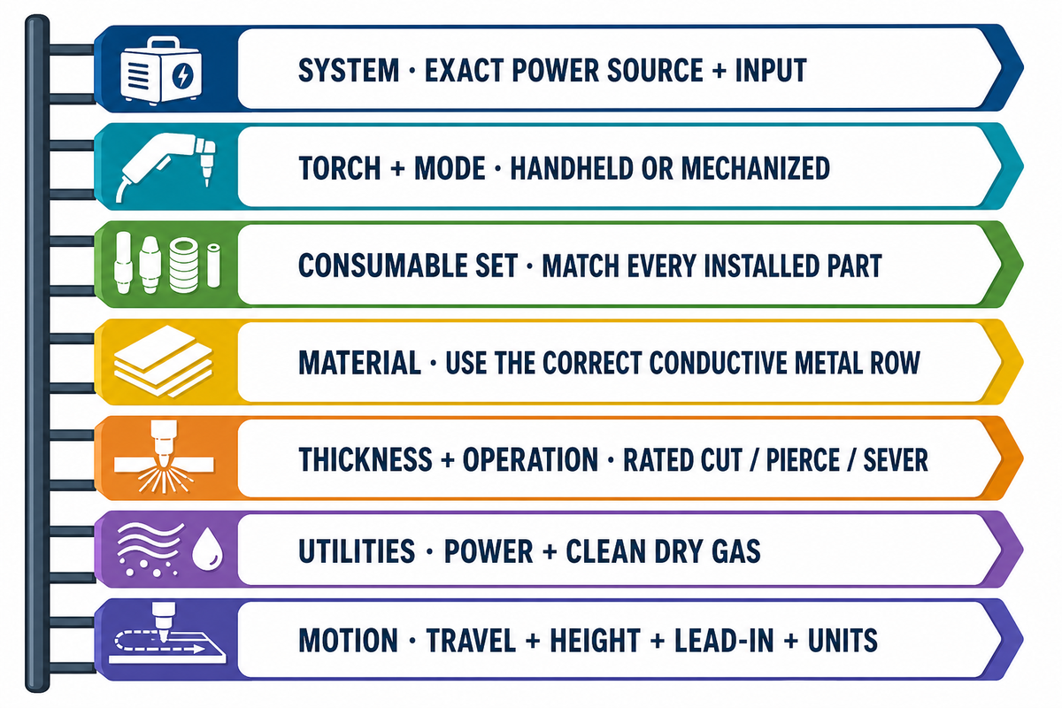
7-Variable Cut-Chart Ladder
Climb this ladder before copying any row. If one doesn’t align with what you found, stop your trial and grab the appropriate chart.
- System: Does the chart list specifications for the specific power source model and input power setup you’re using?
- Torch and mode: Does it match the specific hand-held or mechanized torch being used and the desired drag, standoff, marking, fine-cut, or production mode?
- Consumable set: Are the electrode, nozzle, shield, cap, and rated current the same components installed in your torch?
- Material: Are the specifications in the row for mild steel, stainless steel, aluminum, or the actual conductive metal you’ll be cutting?
- Thickness and operation: Does the listed thickness match the measured thickness, and does the row specify edge start, piercing, rated cut, or severance?
- Utilities: Can the input power and clean, dry gas deliver the required load throughout the cut?
- Motion: Does the row apply to handheld travel or the CNC controller, height control, lead-in, and motion units being used?
- Match the system and torch.
- Match the installed consumable set.
- Measure the actual material thickness.
- Record the baseline result.
- Copy a row by amperage label alone.
- Mix handheld and mechanized values.
- Extrapolate beyond rated-quality capacity.
- Change several variables together.
When not to use a generic web settings chart
Don’t rely on a generic chart when the torch or consumables are unknown, or when the material is coated or unidentified. Stop as well when thickness exceeds rated-quality capacity, air delivery is unstable, the machine reports a fault, or the job has defined roughness, bevel, heat-affected-zone, or thickness tolerances. Get the current manual, verify parts and utilities, then qualify the process on representative material. Generic rows organize questions; they can’t authorize a cut or make an undersized system suitable.
When selecting an industrial plasma system rather than troubleshooting a single cut, review the utility and control requirements for industrial plasma cutting machines. A chart row isn’t a complete purchasing specification; it’s a list of questions to resolve with the supplier before choosing a system.
Plasma Cutter Settings Chart by Material Thickness
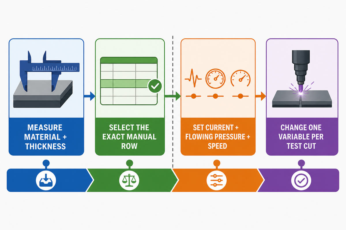
The safest cross-brand chart doesn’t invent a universal PSI or inches-per-minute value. It tells you which machine-specific row to retrieve and how to validate it. The “current class” below is a selection instruction, not an amperage setpoint. Use the exact numeric values printed for your machine and installed consumables.
Practical plasma cutting tips should keep amperage settings from drifting to “high” or “low.” A low-amperage row may require different consumables, and the manual may specify a separate cutting thickness. Verify the thickness of metal and the material you are cutting before any metal cutting trial.
Search labels can hide the missing variables. Results labeled “plasma cutter amperage chart,” “plasma cutter air pressure,” or “CNC plasma cutter settings” still need a model match. “Plasma cutter settings for metal” is too broad, while “plasma cutter settings chart mm” only signals metric thickness. If a query says “Cut 50 plasma cutter settings chart,” identify the actual manufacturer and model before using a row.
| Material and manual-defined thickness class | Amperage selection | Speed selection | Pressure selection | Limitations / Not suitable for |
|---|---|---|---|---|
| Mild steel, the manual’s thinnest supported row | Use the manual’s thin-sheet or low-current consumable row; don’t assume maximum current gives the cleanest edge. | Begin at the chart’s quality speed, not an improvised slow crawl that overheats the sheet. | Use the model’s flowing-pressure or automatic setting. | Full severance without excessive kerf, warping, or low-speed dross. |
| Mild steel, light-gauge range defined by the manual | Choose the exact material/thickness row and matching nozzle current. | Use the chart value, then adjust in a small documented step only after air and consumables pass. | Verify stability during flow. | Sparks exit the bottom; CNC arc remains stable through the lead-in. |
| Mild steel, mid-range rated-quality band in the manual | Use the listed production or best-quality current; don’t mix a higher-current nozzle with a lower-current row. | Separate production speed from best-quality speed. | Use the prescribed gas test under load. | Compare dross direction, edge angle, kerf, and repeatability. |
| Mild steel, upper rated-quality band in the manual | Confirm the thickness is within rated-quality capacity, not only sever capacity. | Start at the model chart; slowing excessively can increase dross and heat input. | Confirm compressor delivery and duty cycle as well as pressure. | Stable penetration through the entire cut, including after the compressor cycles. |
| Mild steel, upper pierce or edge-start band within the manual | Use only a model-specific row that supports this thickness and the intended pierce or edge start. | Don’t infer speed from a smaller machine or another plasma process. | Verify delivered flow, moisture control, and pressure through the cut. | Confirm pierce completion, lead-in, edge angle, and thermal load. |
| Mild steel above the model’s rated-quality range | Do not create a row by extrapolation. Select a suitable power source/process or use a manufacturer-approved sever operation if appropriate. | Model-defined only. | Model-defined only. | A successful sever is not evidence of rated cut quality or production suitability. |
| Stainless steel, any thickness | Use the stainless row for the exact system and gas mode. | Use stainless-specific speed; do not copy mild-steel motion values. | Use the specified gas and flowing check. | Judge edge condition, dross, discoloration, and downstream finish requirements. |
| Aluminum, thin to medium plate | Use an aluminum-specific row and matched consumables. | Do not transfer steel speed by thickness alone. | Follow the machine’s approved air/gas process. | Define whether roughness, burr, heat input, or productivity is the main target. |
| Expanded, coated, rusty, or unknown metal | Identify material and hazards first; a clean-plate row is not automatically valid. | Run a controlled scrap test only after surface and fume controls are resolved. | Confirm air quality and the approved process. | Stable arc transfer and repeatable severance on representative material. |
What are the recommended amp settings for plasma cutting?
Recommended amperage is the value in the exact model’s cut chart for the material, measured thickness, torch, and installed consumable set. Current can be decisive when penetration fails: a 2024 experiment on 2 mm AISI 1020 steel produced surface melting without severance at 15 A, while 20 A penetrated across its tested speed range. That finding supports a current-sufficiency branch; it doesn’t establish a universal 20 A rule.
The AISI 1020 experiment tested travel from 500 mm/min to 4,000 mm/min. Separately, the 2026 robotic study reported that entry-diameter deviation changed from 0.68 ± 0.54 mm to 0.12 ± 0.07 mm after thickness-informed adaptation. These are experimental boundaries, not recommended settings for another machine.
One-Variable Test-Cut Log
The One-Variable Test-Cut Log captures a baseline, one controlled change, and a repeatability check.
Record the baseline before manipulating a setting. A basic log includes these fields: date, machine and torch, material and measured thickness, surface condition, consumable part numbers and condition, amperage, flowing pressure or test result of gas supply, travel speed, standoff or cut height, pierce height and delay for CNC, result, and next one-variable change.
| Test | One change | Hold constant | Observe | Decision |
|---|---|---|---|---|
| 0 — baseline | Geen | Exact chart row | Severance, arc, dross, kerf, edge angle | Choose one plausible variable |
| 1 — correction | Example: a small speed step | Current, pressure, height, consumables | Direction and size of change | Keep, reverse, or inspect another cause |
| 2 — confirmation | No new setting | Winning condition | Repeatability on representative geometry | Approve or continue controlled testing |
A quality cut has a clearly stated goal. Maximum output rate, minimum dross, minimum roughness, narrow kerf, minimal heat-affected zone, extended consumable life, and reliable piercing don’t invariably coincide at one setting. A 2024 aluminum study found that amperage was the most influential variable on surface roughness while the measured thickness was the most influential variable on burr height. Use that information as a prompt to declare your goal, not as a ready recipe for aluminum.
Set Air Pressure Under Flow, Not at Static Gauge Pressure
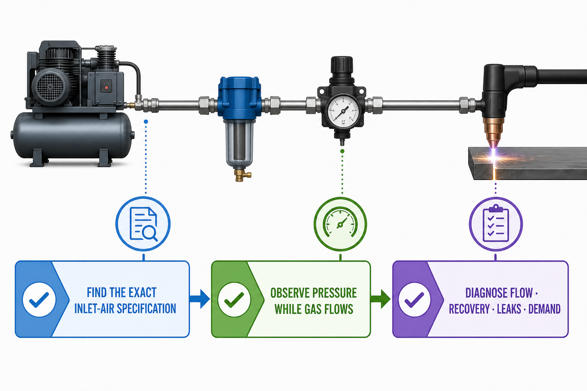
Universal PSI levels can’t be justified across all brands and types of plasma cutter. A regulator can show acceptable pressure while idle and still sag when the solenoid opens, the torch flows gas, or a different machine tool draws from the same line. Pressure also isn’t flow: a restrictive hose, saturated filter, undersized compressor, long pipe run, or low duty cycle can deprive a tool of air even if the gauge reads the correct number.
A responsible check records amps and air pressure as separate controls. The air pressure regulator sets an anticipated target, but the pressure gauge must still reflect the correct pressure during actual use. IPM ties to motion command, PSI to the gas circuit. Neither can make up for an undersized compressor.
- Find the exact inlet-air specification and the manufacturer’s test or purge procedure.
- Complete the specified test and observe pressure as gas flows. Document any reduction or fluctuation.
- If pressure drops, check available flow, compressor duty cycle, tank recovery, hose diameter and length, fittings, filters, moisture separator, leaks, and simultaneous demand before modifying the torch process.
What PSI should a plasma cutter be set at?
Adjust pressure to the value or automatic setting specified for the exact machine and torch, measured with the manufacturer’s flowing test. Avoid copying a universal internet number. If the machine specifies inlet pressure and a minimum flow rate, both conditions must be met. For supply planning, use the separate guide to size an air compressor for plasma cutting.
How Material Changes the Starting Point
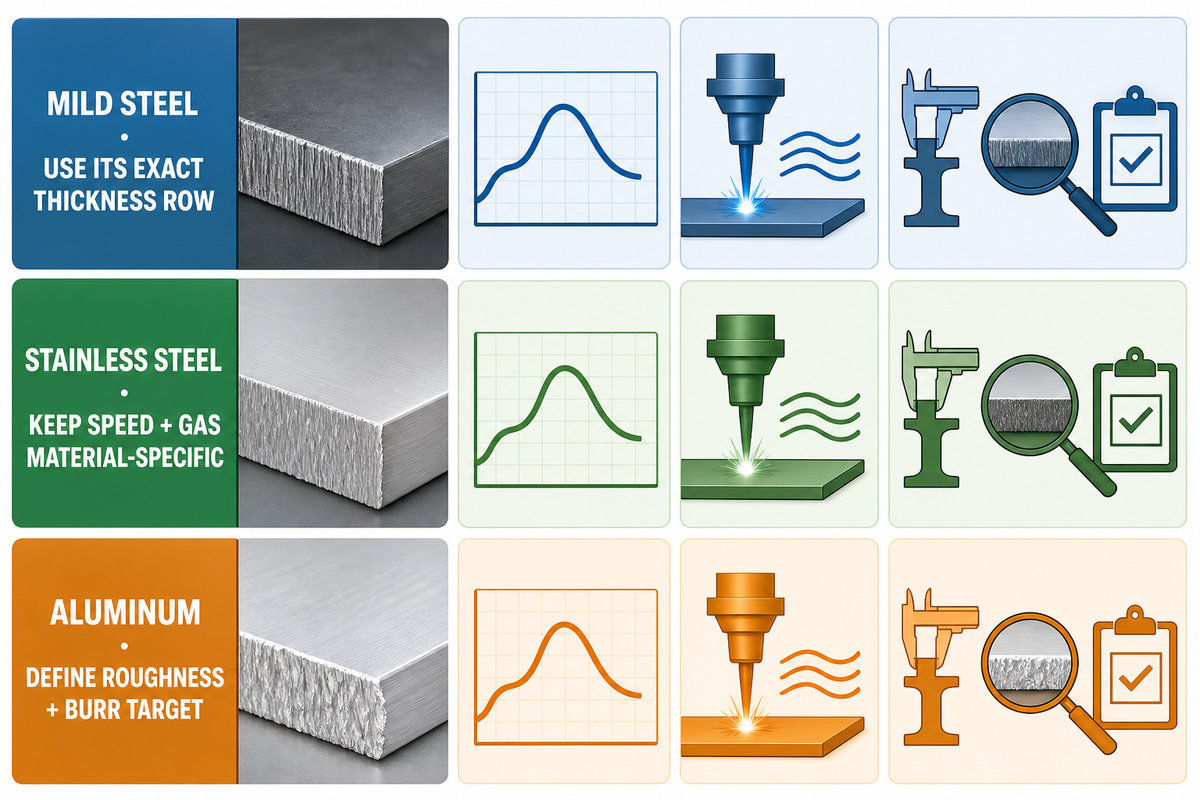
Plasma cuts electrically conductive metals, but equal thickness doesn’t make mild steel, stainless steel, and aluminum interchangeable. Material chemistry, thermal behavior, surface condition, gas process, downstream finish, and the accepted definition of quality can change the correct row and the result you should inspect.
When cutting stainless steel, the type of metal and metal thicknesses belong in the log, not just “sheet.” Record the actual material and thickness, workpiece surface, and metal plate condition because molten flow, dross adhesion, and finishing expectations change the interpretation of the same visible edge.
Dross Direction Diagnostic Matrix
The Dross Direction Diagnostic Matrix converts a visible cut symptom into the next prerequisite or single-variable test.
| Materiaal | What changes | Do not copy | Next check |
|---|---|---|---|
| Mild steel | Consumable class, current, speed, height, and pierce data by measured thickness. | A sever-capacity claim as a quality-cut row. | Dross direction, edge angle, and heat input. |
| Stainless steel | Material-specific speed/gas process and finish requirements. | A mild-steel row merely because thickness matches. | Fume controls, discoloration, edge chemistry, and downstream finishing. |
| Aluminium | Approved gas/air mode, alloy and plate behavior, roughness and burr target. | Steel current or travel speed by thickness alone. | Use the dedicated guide to aluminum plasma cutting settings and gas selection. |
Read Dross, Sparks, Kerf, and Edge Angle Before Changing Amps
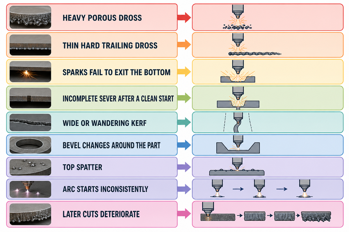
When the selected current is sufficient to penetrate, poor cut quality often comes from speed, height, air delivery, consumable wear, or the electrical path. The sequence matters. First confirm safety, exact chart applicability, flowing air, the work lead, and the consumable stack. Then use the cut symptom to choose one test.
Cutting results become useful evidence only when the baseline is recorded. Cutting too slow can add heat and heavy dross; excessive speed can leave hard trailing dross. Kerf width, standoff distance, and arc stability help improve cut quality while the log also protects the life of your consumables.
| Symptom | Likely branch | Verify first | Test / limitation |
|---|---|---|---|
| Heavy, porous dross that is easy to remove | Low-speed dross / excess heat input | Correct chart and height | Increase speed one documented step. |
| Thin, hard dross trailing the cut | High-speed dross | Flowing pressure and current sufficiency | Reduce speed one documented step. |
| Sparks spray upward or fail to exit the bottom | Speed too high, current insufficient, excessive height, or air/consumable problem | Manual row, current, air, consumables | Correct the failed prerequisite; only then test speed. |
| Incomplete sever after a clean start | Pressure/flow sag, duty cycle, input-power drop, current limit, or worn electrode | Live pressure, alarms, input power | Restore the failed utility; repeat baseline. |
| Wide or wandering kerf | Worn nozzle/electrode, excessive height, slow speed, or excess current for the consumable | Nozzle orifice and torch stack | Install verified consumables; repeat baseline. |
| Bevel changes around the part | Torch not square, height variation, travel direction, or worn parts | Torch squareness and height control | Correct alignment before changing current. |
| Top spatter | Height, speed, or pierce timing | Pierce height/delay and cut height | Apply the exact mechanized chart value. |
| Arc starts inconsistently | Consumable wear, moisture, work lead, start signal, or transfer distance | Parts, air quality, electrical contact | Correct one failed condition; do not tune speed. |
| First cuts pass, later cuts deteriorate | Compressor recovery, moisture, duty cycle, thermal drift, or consumable damage | Time-based log and alarms | Repeat at the same setting after restoring capacity. |
Is the cutting speed too fast or too slow?
If sparks trail sharply and fail to pass through, or thin hard dross follows the cut, speed may be too high, but insufficient current, excessive height, worn consumables, and low delivered air can look similar. Heavy porous dross and excessive heat suggest a too-slow branch. Confirm prerequisites first, then make a small speed change and compare directionally. For part-specific inspection and replacement decisions, inspect plasma cutter consumables before blaming the power source.
Handheld vs CNC: When Height, Delay, and Arc Voltage Enter
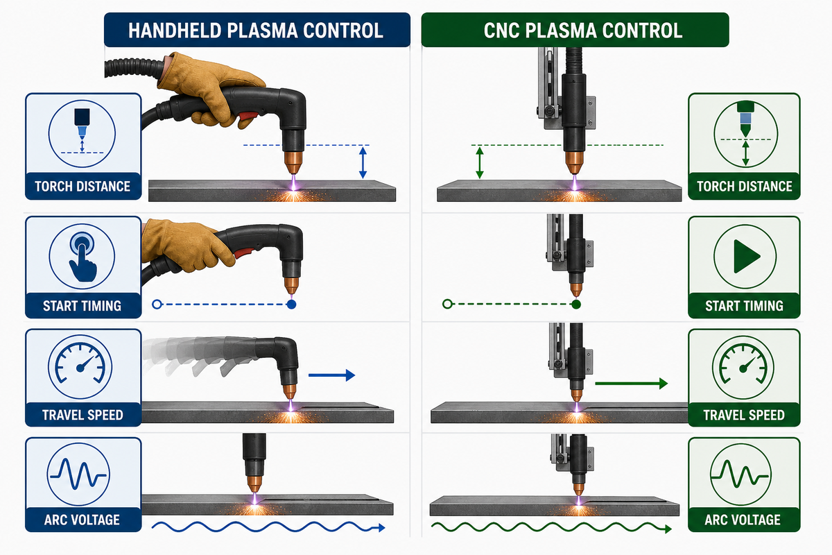
A hand-held torch relies on the operator to hold travel and standoff, while a CNC plasma cutting table adds programmed cut path, pierce timing, and torch-to-work distance control. A plasma machine row is valid only when its motion units and control assumptions match the installed system. Table selection and control architecture belong in the CNC plasma table selection guide.
| Control | Handheld | CNC/mechanized |
|---|---|---|
| Torch distance | Drag or manual standoff as permitted by torch/consumables. | Separate pierce height and cut height, often managed by height control. |
| Start timing | Operator controls trigger and motion. | Pierce delay, arc-ok signal, lead-in, and motion sequence matter. |
| Speed | Operator watches sparks and maintains steady travel. | Controller units, acceleration, corners, and programmed feed must match the chart. |
| Voltage | Usually not a direct travel-height control. | Arc-voltage target can influence torch height after transfer. |
What is 2T and 4T on a plasma cutter?
2T and 4T are trigger-control modes, not cutting-power settings. In a common 2T arrangement, the operator holds the trigger during the cut; 4T may latch the torch on through a press/release sequence until another trigger action ends the cut. Exact behavior is model-specific. Neither mode replaces the amperage, pressure, speed, standoff, or CNC timing required by the cut chart.
Integration and Utility Requirements That Can Invalidate the Chart

Hidden Utility Bottleneck Map
- Input power: voltage, phase, breaker, conductor, generator compatibility, and allowable voltage drop under load.
- Duty cycle: cutting current and ambient conditions at the required production duration.
- Compressed air or gas: pressure under flow, required delivery, compressor recovery, line size, dryness, filtration, and other simultaneous consumers.
- Electrical return: clean work-lead contact, table grounding/bonding, and routing that follows the equipment instructions.
- Mechanized interface: start, arc-ok, voltage divider, height control, controller units, nesting assumptions, and emergency-stop integration.
- Production evidence: keep the exact cut-chart revision, consumable part numbers, representative sample cut, acceptance criteria, and a repeatable test log.
This checklist turns a vague request for “the right plasma setting” into a commissioning conversation. Operators need a stable arc and a clear diagnosis. Maintenance needs utilities that stay within specification. Quality teams need repeatable acceptance criteria. Procurement needs evidence that the power, air, torch, controller, and production objective fit together.
RFQ checklist — copy these into your quote request:
| Parameter | Recommended range | Why it matters | How to verify |
|---|---|---|---|
| Material thickness | Production minimum–maximum, mm | Controls process and current class | List measured plate samples |
| Cut-quality target | Buyer-defined tolerance, mm | Separates severing from accepted parts | Approve a representative test cut |
| Air/gas delivery | Model-required pressure and flow | Prevents pressure sag | Record a flowing test |
| Duty requirement | Cutting minutes per 10-minute cycle | Sizes power and cooling capacity | Run the production cycle |
| CNC interface | Start, arc-ok, voltage, height-control signals | Controls pierce and cut sequence | Review the interface drawing |
| Consumable package | Part numbers by current and material | Binds the chart to installed parts | Match labels to the cut chart |
Recent research points in the same direction without making ordinary cut charts redundant. A 2026 robotic hole-cutting investigation measured plate thickness and adapted speed and path planning; in that specific experiment, entry-diameter deviation fell by 82.4%. The result shows that feedback and material variation can matter in mechanized production. It isn’t a handheld-tool promise or a reason to ignore the approved chart.
Veelgestelde vragen
Can one plasma cutter settings chart work for every brand?
Answer
Should amperage always be set to maximum?
Answer
Why does the cutter stop penetrating after a few seconds?
Answer
Is low-speed dross the same as high-speed dross?
Answer
When should you replace the nozzle or electrode instead of changing settings?
Answer
Can the same settings be used for steel, stainless steel, and aluminum?
Answer
Final Setting Rule
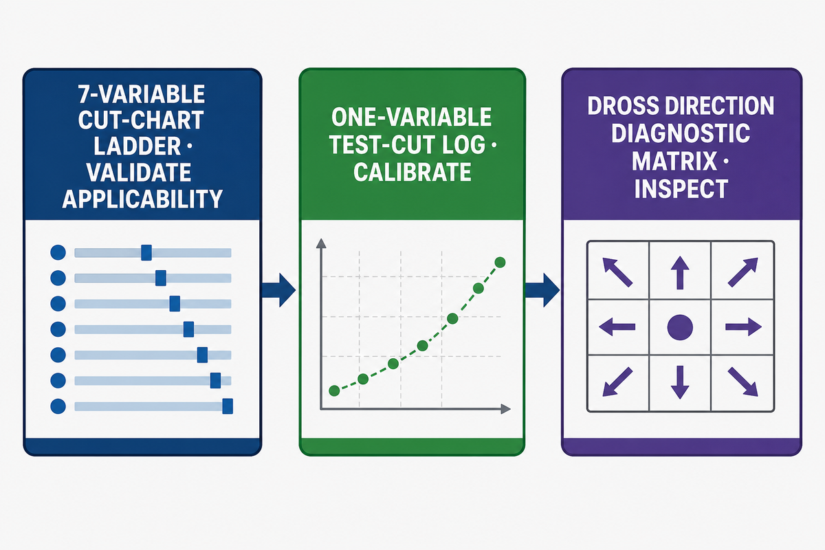
Use thickness to find the neighborhood, the exact manual to select the row, and a controlled test cut to prove it. The reliable sequence is the 7-Variable Cut-Chart Ladder, followed by the One-Variable Test-Cut Log and, only after prerequisites pass, the Dross Direction Diagnostic Matrix. That sequence protects the operator from a plausible number that belongs to the wrong machine or problem.
Measured thickness selects the neighborhood; the exact machine chart selects the row; one-variable test cuts establish the usable production setting.
Turn the chart into a machine specification
Define your material range, desired cut quality, production duty, air supply, and CNC interface before requesting a configuration.
Related Plasma Cutting Guides
- Air compressor requirements for a plasma cutter
- Plasma cutter consumable inspection and replacement
- Plasma cutter settings for aluminum
- Plasma cutting vs laser cutting
Editorial transparency: this article uses public regulations, academic research, technical literature, and RESIZE’s public site structure. No RESIZE model-specific cut chart or private shop-test dataset was supplied. The article therefore doesn’t claim proprietary amperage, speed, pressure, or cut-quality results.
References & Sources
- OSHA 29 CFR 1910.252 U.S. Occupational Safety and Health Administration
- OSHA 29 CFR 1926.353 U.S. Occupational Safety and Health Administration
- Archived plasma arc cutting reference with an age warning The Open University
- 2024 AISI 1020 plasma-cutting experiment Nigerian Journal of Engineering Science and Technology Research
- 2024 aluminum plasma-cutting parameter study High Temperature Materials and Processes
- 2026 thickness-informed robotic plasma hole-cutting study The International Journal of Advanced Manufacturing Technology