Welding equipment for structural steel fabrication handles the movement of heavier steel members within your shop bay. Each style of steel member requires different combinations of arc power sources and mechanical handling devices. A high-output torch won’t reduce cycle time if the assembly waits for an overhead crane to move each joint rotation.
Shop bay purchasers should match three layers of hardware prior to requesting quotes from suppliers. First, determine the power sources and wire feeders appropriate for submerged arc welding and flux-cored connections. Second, pick column and boom manipulators, tilting positioners, or turning rolls. Finally, add stations to preheat, cut, and/or clamp the joint to a tolerance prior to welding.
By GW · Updated November 2026
Structural Steel Welding Equipment: Shop vs Field Setup Scope
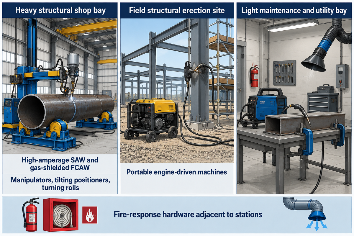
Structural steel fabrication shops operate under different electrical, lifting, and environmental constraints than field erection sites. Shop stations rely on three-phase industrial power and overhead bridge cranes. Handling machinery, and positioning units. Field erection sites rely on portable engine driven generators and self-shielded wires to splice members.
Results of Internet searches for structural welding machines often include bare equipment systems and portable consumer inverters. Light machines built for a home garage, a diy project, auto body work, or thin automotive repairs cannot sustain continuous structural production. Even a durable pro multi-process welder sold for automotive panels lacks hardware for flux and wire, and efficiency to deposit metal on thick sections.
| Operating environment | Primary power and process package | Workpiece handling method | Governing buyer check |
|---|---|---|---|
| Heavy structural shop bay | High-amperage submerged arc and gas-shielded flux-cored systems | Column-and-boom manipulators, tilting positioners, and turning rolls | Does the complete cell hold flat-position deposition without crane delays? |
| Field structural erection site | Portable engine-driven constant-current and constant-voltage machines | Fixed structure with scaffold, lift, and manual clamping access | Can operators maintain root penetration and shielding under wind exposure? |
| Light maintenance and utility bay | Single-phase or light three-phase mig, tig welding, and stick rod units | Manual bench clamps and light rotary turntables | Is the machine restricted to non-load-bearing brackets and light repair work? |
Provisions for workplace safety should be included in the initial equipment specification, because welding stations occupy permanent floor space. In the United States, the Occupational Safety and Health Administration sets mandatory shop rules for fire prevention, ventilation, and operator protection. Every bay layout must ensure that fire-response hardware is located adjacent to welding stations.
“Suitable fire extinguishing equipment shall be maintained in a state of readiness for instant use.”
Fume management also shapes bay architecture when shops weld stainless attachments or coated structural assemblies. Where exposure to hexavalent chromium falls under OSHA 29 CFR 1910.1026, employers must evaluate employee exposure and employ feasible engineering controls. Local fume extraction hoods or gun-mounted fume extraction, in conjunction with the power source, must be provided. Don’t view ventilation as a post-installation retrofit.
H-Beam, Box Column, and Truss Welding Setup by Member Geometry
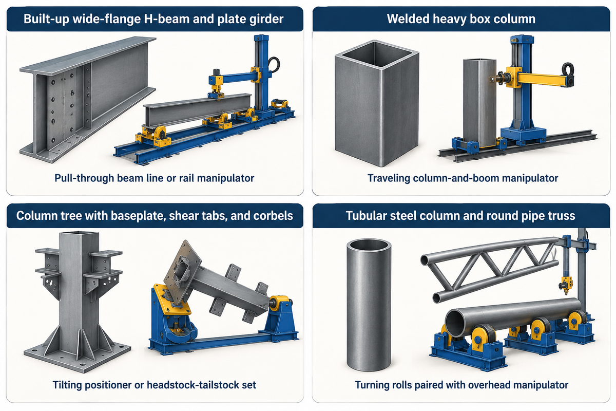
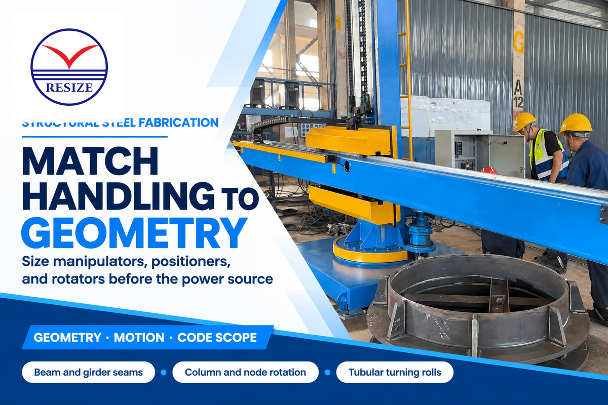
The axis of motion during welding is dictated by the member geometry. Long, straight web-to-flange fillets of wide-flange H-beams require long linear travel of a torch. Heavy box columns require internal diaphragm welding before external corner groove seams close the section. Rotational indexing of a welder is required to weld branch intersections of a space truss, if the branch intersections aren’t aligned with the main span of the truss.
The Member-to-Motion Envelope Matrix below maps common structural assemblies to their primary arc process, motion axis, and production bottleneck. Use this matrix to help identify linear gantry work from rotary positioning work prior to requesting machinery quotes.
| Structural member family | Typical joint configuration | Target weld position | Primary motion equipment family | Critical shop bottleneck check |
|---|---|---|---|---|
| Built-up wide-flange H-beam and plate girder | Longitudinal web-to-flange fillet or complete-penetration T-joints | Flat boat position or horizontal fillet | Pull-through beam line or rail-traveling manipulator over tilted bed | Overhead crane wait time for beam flipping and flange straightening |
| Welded heavy box column | Internal continuity plates and four external longitudinal corner grooves | Flat downhand groove and vertical electroslag channel | Traveling column-and-boom manipulator with narrow-gap or tandem head | Internal diaphragm heat input and distortion control across the four corners |
| Column tree with baseplate, shear tabs, and corbels | Short multi-pass fillets and bevel grooves around all four column faces | Flat position via table tilt and rotation | Two-axis tilting positioner or synchronized headstock-tailstock set | Eccentric center-of-gravity torque and swing clearance above the shop floor |
| Tubular steel column and round pipe truss | Circumferential butt splices and contoured branch saddle joints | Flat rolling position at top dead center | Self-aligning or adjustable turning rolls paired with overhead manipulator | Axial spiral creep during rotation and trunnion load on thin pipe walls |
Standard beam lines don’t address equipment challenges presented by closed box columns. Manual welders have trouble reaching internal connections in the box columns. A research article published in the AISC Engineering Journal on box-column electroslag welding describes methods to reduce brittle fracture risk due to seismic loading. An article in STRUCTURE Magazine focuses on electroslag equipment and describes the necessary fabrication steps to control distortion.
Consider a structural shop bidding on a mixed commercial building package. Drawings include straight floor beams, box columns, and heavier corbeled columns. If the bid wins only a fixed horizontal beam line, the box columns and heavier corbeled columns would still be on manual skids awaiting crane flips. The best course of action is to split the budget between a long-seam welding machine and a rotary positioning device.
Column and Boom Welding Manipulator Sizing for Long Girder Seams
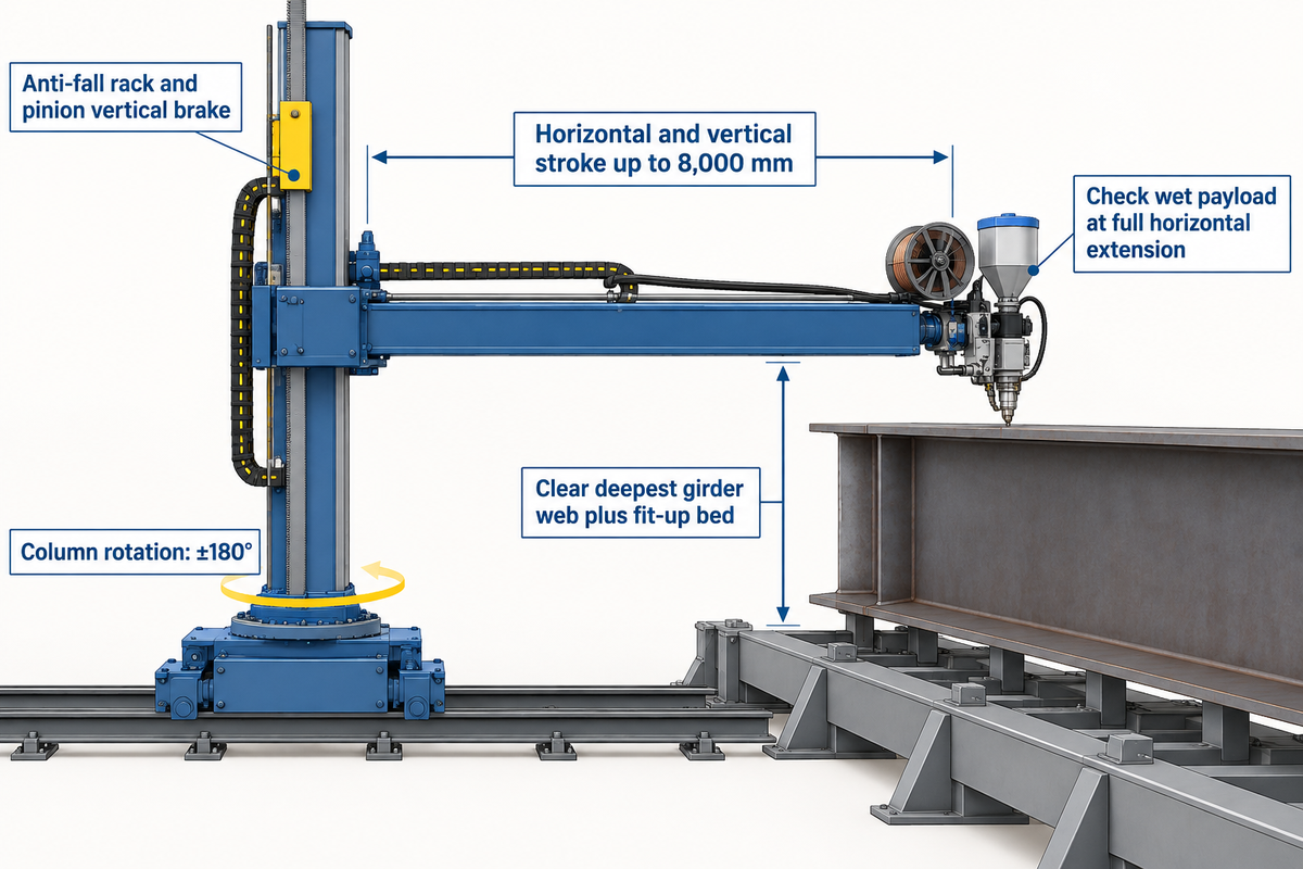
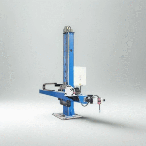
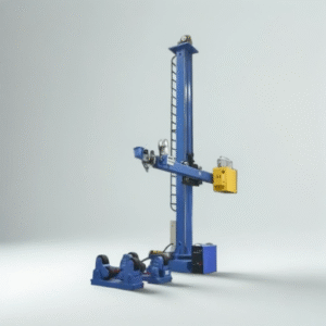
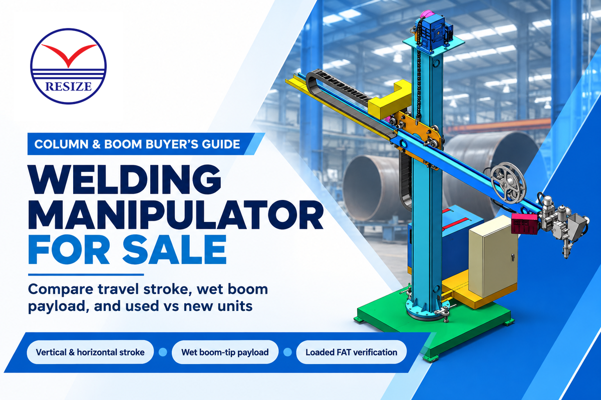
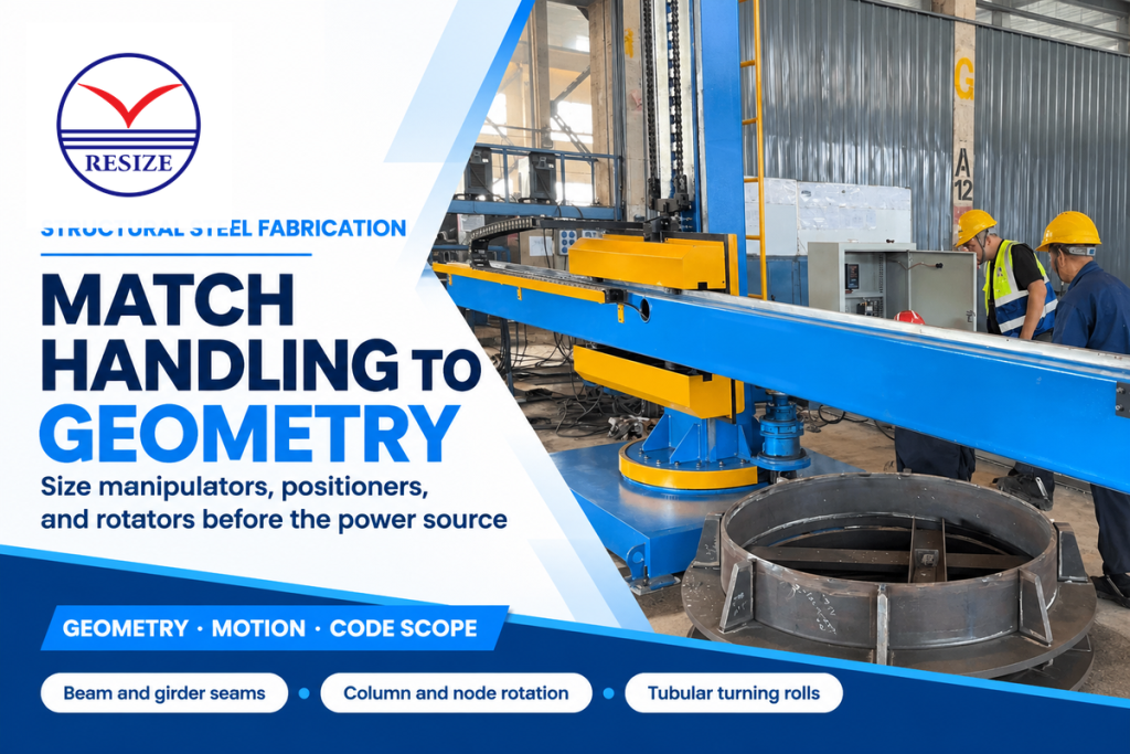
A welding manipulator moves the welding head in the vertical and horizontal planes while a motorized travel car moves the column in the longitudinal direction along a track.
Reach and stroke are two important concepts discussed in RESIZE’s guide to column and boom welding manipulator sizing. Reach is a position defined by a datum. Stroke is travel between mechanical limits. Working height is the distance the tip of the torch is above the finished level of the shop floor. When specifying a column and boom welding manipulator, always check the deepest web of the lower girder first. Make sure the vertical stroke clearance is greater than the height of the web plus fit-up bed or turning rolls.
Quick Specs: RESIZE Heavy Manipulator Envelope
RESIZE’s published heavy manipulator parameter table lists horizontal and vertical boom travel strokes up to 8,000 mm with ±180° column rotation. Always check the rated boom-tip load separately at full horizontal extension with all welding heads, wire reels, and flux hoppers filled.
Buyers underestimate total wet payload at the end of the boom. A structural submerged arc package should include the welding head, motorized cross-slides, seam-tracking sensors, thick power cables, and a heated flux hopper. Also needed are wire spools. A bend in the mast and cross-arm can occur when the boom extends across two parallel girder beds. Have the manufacturer state maximum vertical droop under full wet load at maximum extension to approve the drawing.
Rail travel and vertical safety locks merit similar scrutiny when you purchase a long seam station. If the torch is carried along a longitudinal box-column seam in the travel car, variations in speed, particularly a momentary speed-up, can adversely affect the heat input. A mechanical anti-fall rack and pinion brake is an essential safety feature on the vertical carriage. It prevents the boom from falling if a lift chain fails above an assembly that crews build on the floor.
Welding Positioners and Headstock-Tailstock Sets for Columns and Nodes
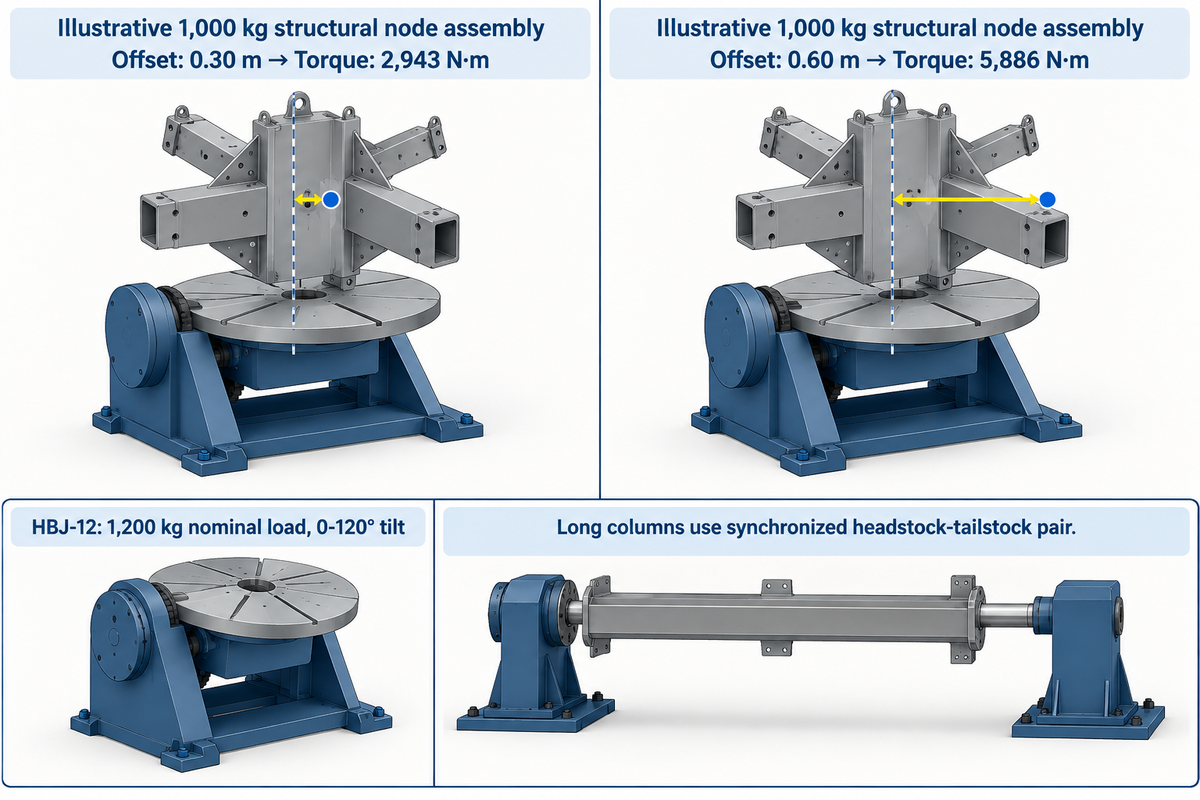
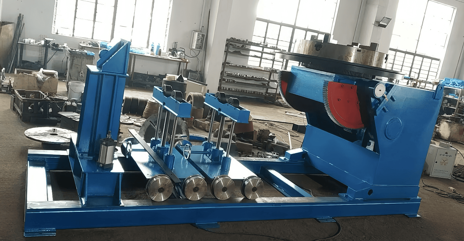
A welding positioner rotates and tilts a clamped structural assembly so that the welder can deposit metal in a flat downhand position. Moving a column baseplate from a vertical or overhead position to a flat, horizontal position also helps to reduce the rate of inclusions and improves the deposition rate. Local table rotation eliminates repeated overhead crane lifts during multiple welding operations.
Shop case reports confirm that material handling often governs structural bay output. In a report from The Fabricator on deploying heavy welding positioners, shop management noted the direct impact on crane demand.
“With the positioner, we’ve eliminated handling time and the use of overhead cranes.”
Consider other factors besides workpiece weight and nameplate tonnage when deciding on a zware laspositioneerder. Some structural brackets position the center of gravity of the workpiece in front of the table and off-center from the rotation axis. The AWS Welding Digest suggests that clamping fixtures affect the stability of the machine.
The UCLA Physics Reference on torque states that the magnitude of a static torque is equal to the force acting on it multiplied by the moment arm. Consider an illustrative 1,000 kg structural node assembly with its center of gravity at a 0.30 m radial offset. The static gravity torque is equal to 1,000 × 9.81 × 0.30 = 2,943 N·m. If we double that offset to 0.60 m, the static torque increases to 5,886 N·m. Always match both rotational eccentricity and axial overhang against the supplier’s load-distance chart.
There are published vendor ratings that illustrate how table capacity is negatively impacted by swing clearance and offset. In Koike’s guide on how to size a positioner, engineers warn that overlooking swing clearance is a common mistake when specifying positioners for eccentric weldments. On the client catalog side, RESIZE’s published HBJ-12 row lists a 1,200 kg nominal load, 0.05–0.5 rpm rotation, 0–120° tilt, and a 1,200 mm table. Long columns or bridge girders cannot tilt on a single table without touching the floor. Specify a synchronized headstock-tailstock positioner pair to rotate those long members around their longitudinal axis.
Welding Rotators for Tubular Steel Columns and Pipe Trusses
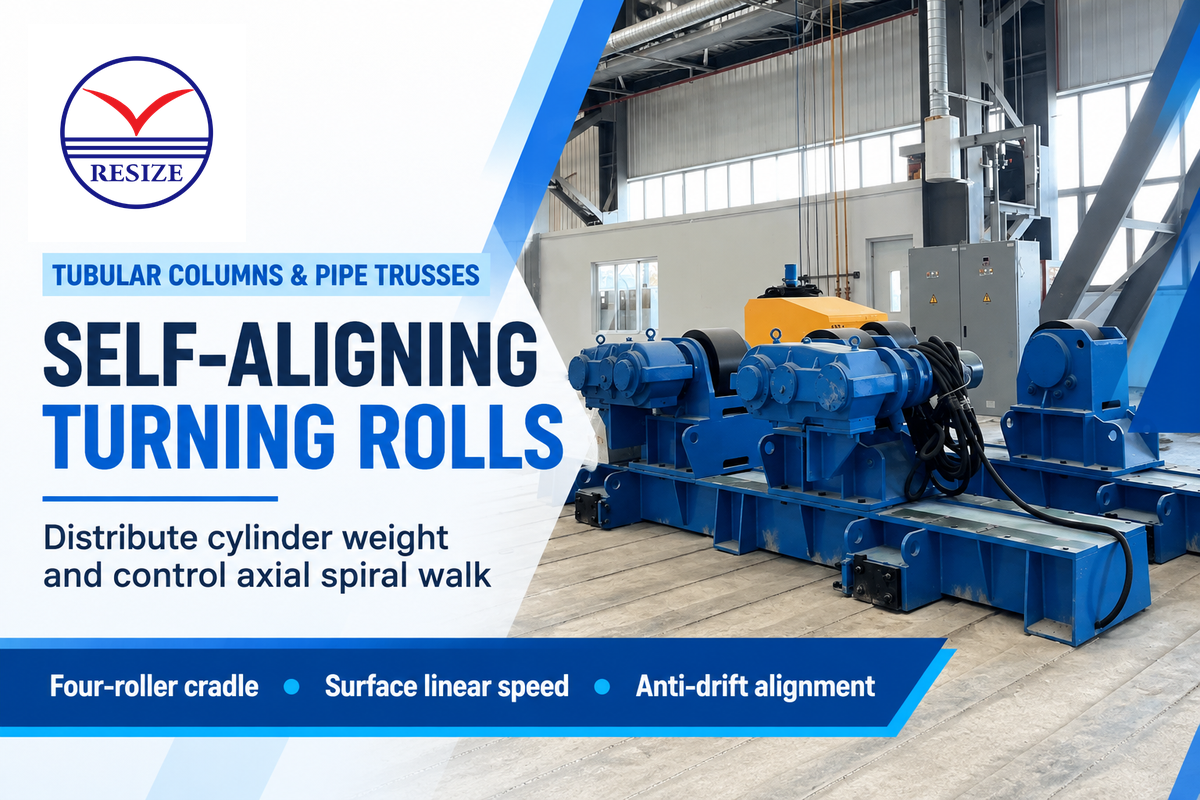
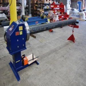
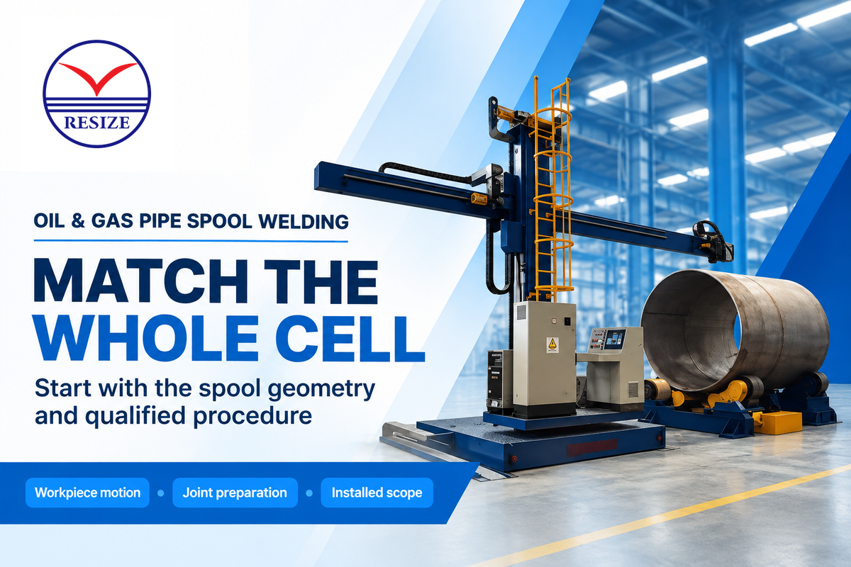
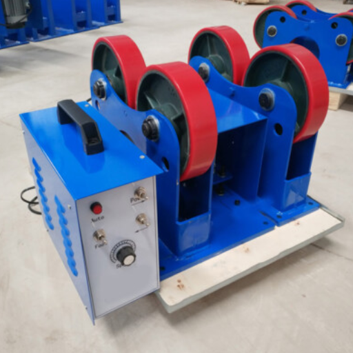
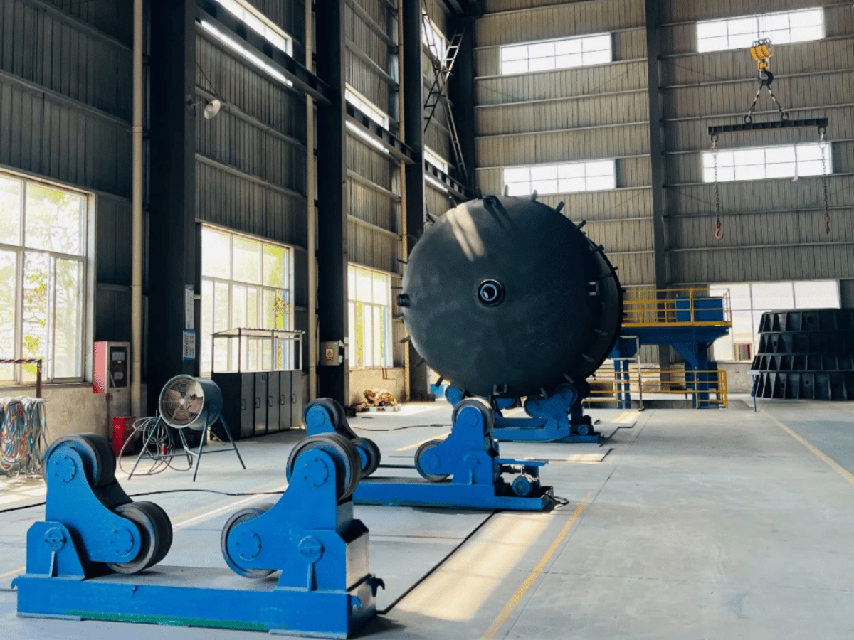
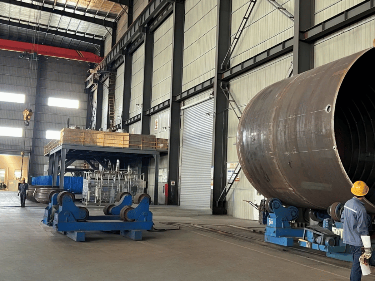
Round structural columns, arch tubes, and wind-tower cans require powered turning rolls to rotate circumferential butt splices beneath a stationary or manipulator-mounted torch. The selection of a self-aligning rotator versus a conventional adjustable roller bed is based on factors such as wall thickness and diameter, and type and position of attachments.
A self-aligning welding rotator uses four pivoted roller carriages that adjust their included angle as the cylinder diameter changes. Distributing the weight across four rollers per bed reduces wall indentation. RESIZE’s published HGZ rotator table shows models from HGZ-5 to HGZ-150 with the HGZ-20 having a maximum load of 20 t with roller linear speed of 6-60 m/h. Note that rotator speed is surface linear travel in meters per hour and not spindle revolutions per minute.
Long tubular columns introduce an operational hazard known as axial spiral walk or corkscrewing. Minor variations in pipe roundness and roller bed alignment cause the cylinder to creep lengthwise along roller beds during successive passes. This effect can be eliminated by laser-aligning the roller beds in the same plane as the column axis. Thrust stops and anti-drift sensors should be provided for long splices.
SAW, FCAW, and Multi-Process Power Sources for Heavy Structural Steel
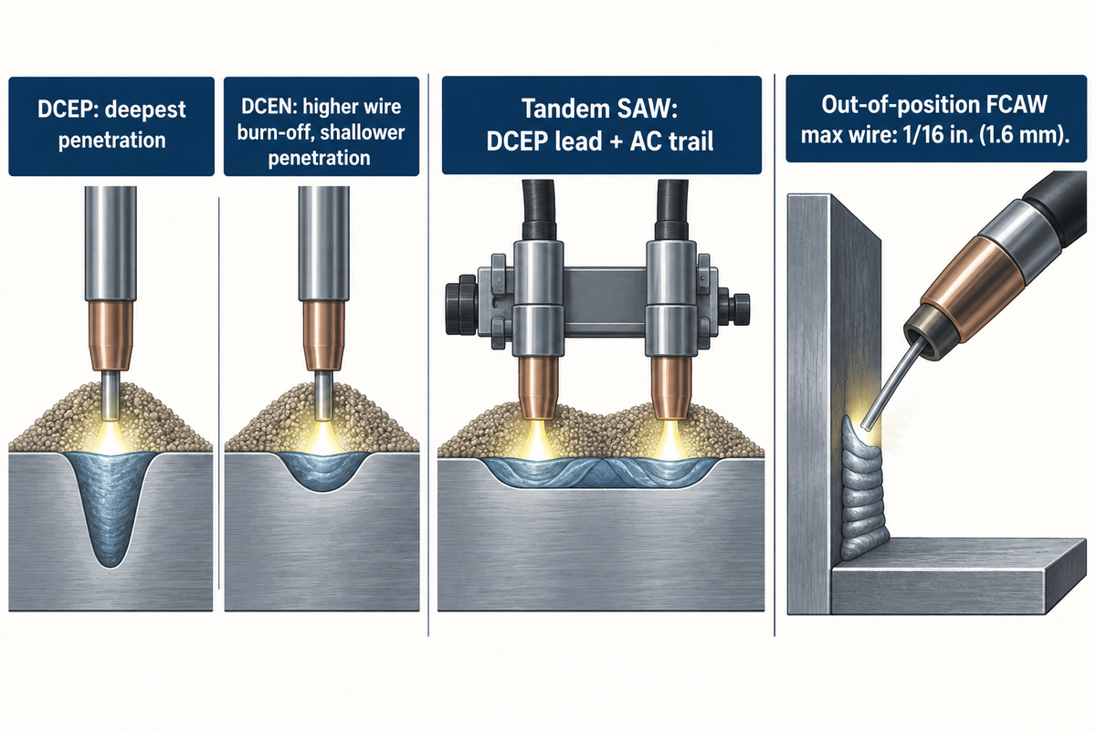
Heavy structural bays require two main arc processes for thick plate fabrication. Long, flat, and/or horizontal seams are processed using submerged arc welding, while stiffeners and out of position connections are processed using gas-shielded flux-cored arc welding. Each process requires a different power supply, duty cycle and wire feed mechanism.
TWI’s technical guide on submerged arc electrode polarity states that for the direct current electrode positive method, the deepest weld penetration is achieved. On the other hand, the direct current electrode negative method increases wire burn-off rate with shallower penetration. When shops run tandem submerged arc systems on thick girder seams, TWI notes that the standard polarity pairing is direct current electrode positive on the lead electrode and alternating current on the trail electrode to minimize arc blow. Alternating current helps overcome magnetic arc blow at the heavy structural joint ends as mentioned in TWI’s submerged arc equipment overview en Lincoln Electric’s penetration variable guide.
For connection detailing and out-of-position assembly, the combination of a gas-shielded flux-cored wire provides high deposition with visible arc control. In Lincoln Electric’s out-of-position FCAW wire guide, the largest electrode diameter classified to run successfully out-of position is 1/16 in. (1.6 mm) wire, and flat and horizontal work can use larger diameter electrodes. Pair these electrodes with heavy industrial wire feeders and constant-voltage power sources capable of holding stable arc voltage across long boom cables.
Bevel Cutting, Fit-Up Clamping, and Preheat Support Equipment
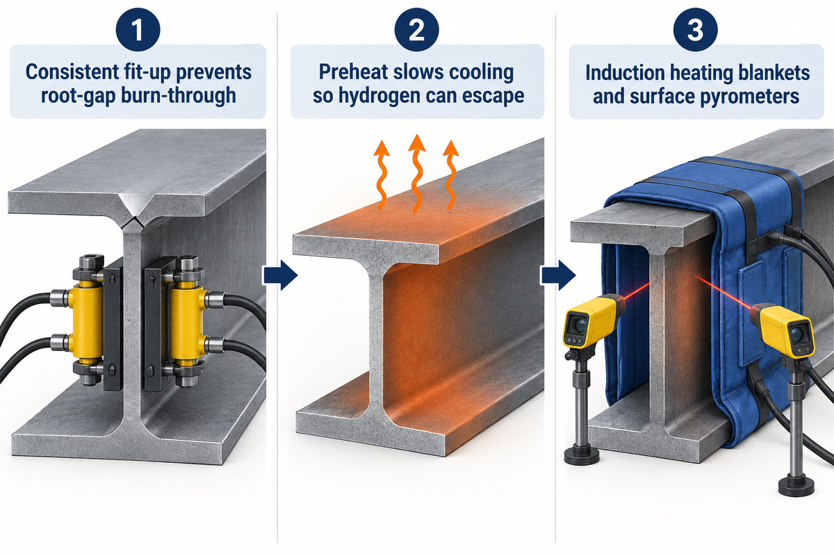
Mechanized welding heads can’t compensate for inconsistent joint bevels, variable root openings, and moisture contaminated plates. Supporting equipment for plate beveling, hydraulic web-to-flange clamping, controlled preheating, and flux conditioning determines whether an automated welding station runs continuously or stops for manual repair.
As highlighted in The Fabricator’s assessment of welding automation readiness, even the best automated cell can do little to compensate for poor weld prep and inconsistent fit-up. Consistent fit-up helps prevent high-current submerged-arc torches from burning through root gaps during the production of H-beams.
Thick structural plates and restrained box-column joints also require some pre-heat to slow cooling rates to allow diffusible hydrogen to escape. The summary of AWS D1.1 by Lincoln Electric on structural preheating outlines the requirements of soak zones. Minimum preheat temperature must be established at a distance at least equal to the thickness of the thickest welded member. Uniform soak temperatures on thick flanges are more achievable with induction heating blankets and calibrated surface pyrometers as compared to manual torches.
AWS D1.1, AISC, and ISO 14732 Controls for Structural Welding Equipment
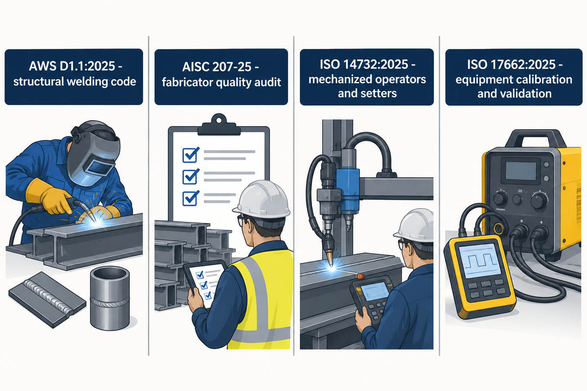
Structural welding codes define how shop equipment is calibrated, how mechanized operators are qualified, and how quality records are audited. Buyers should separate the requirements on qualification of personnel and procedures from kinematic calibration of equipment in every procurement specification prior to issuance of a purchase order for new bay machinery.
In North America, the publication of the latest version of the AWS D1.1:2025 Structural Welding Code – Steel created the need for revisions to requirements pertaining to procedure qualification, welder and welding operator qualification, fabrication, and inspection. Shops in the AISC Certified Fabricators Program are currently audited against the quality management system requirements of AISC 207-25 (effective February 1, 2026). The audits evaluate if welding machines, ammeters, voltmeters, and flux ovens are calibrated and verified, so the operators can hold the qualified heat input parameters on the shop floor.
Parallel international standards exist for verification of mechanized personnel and production equipment. ISO 14732:2025, published in June 2025, specifies qualification testing of welding operators and weld setters for mechanized and automatic welding of metallic materials. It excludes personnel who neither adjust welding parameters nor set up equipment. Separately, ISO 17662:2025, published in September 2025, covers calibration, verification, and validation of welding equipment used in production, while excluding new-equipment manufacture and final product inspection instruments.
Pull-Through H-Beam Line vs Manipulator Cell: Cost and Crane-Time ROI
When increasing the structural capacity of a plant, managers usually compare a dedicated pull-through H-beam welding line against a flexible rail-traveling column and boom manipulator paired with positioners. The choice between the two depends on a number of factors, including the variety of members to be welded, the available floor space and where the greatest number of lost labor hours are occurring.
Published OEM and academic studies show both the potential and the limits of automation. In Lincoln Electric’s structural steel automation case study, semi-automatic welding took 40 minutes to weld one collar piece to a beam, or one hour and twenty minutes per beam, before automated cells cut cycle time.
A 2025 University of North Dakota study on high-mix, low-volume welding reported a 39% cycle time reduction and 41%-71% energy savings in single-sided cobotic applications. Meanwhile, Voortman’s automated versus manual welding comparison advises buyers against over-automating straightforward jobs.
“While robotic welding offers significant advantages in many situations, it is not always the most efficient choice. Manual welding is more practical for simple assemblies.”
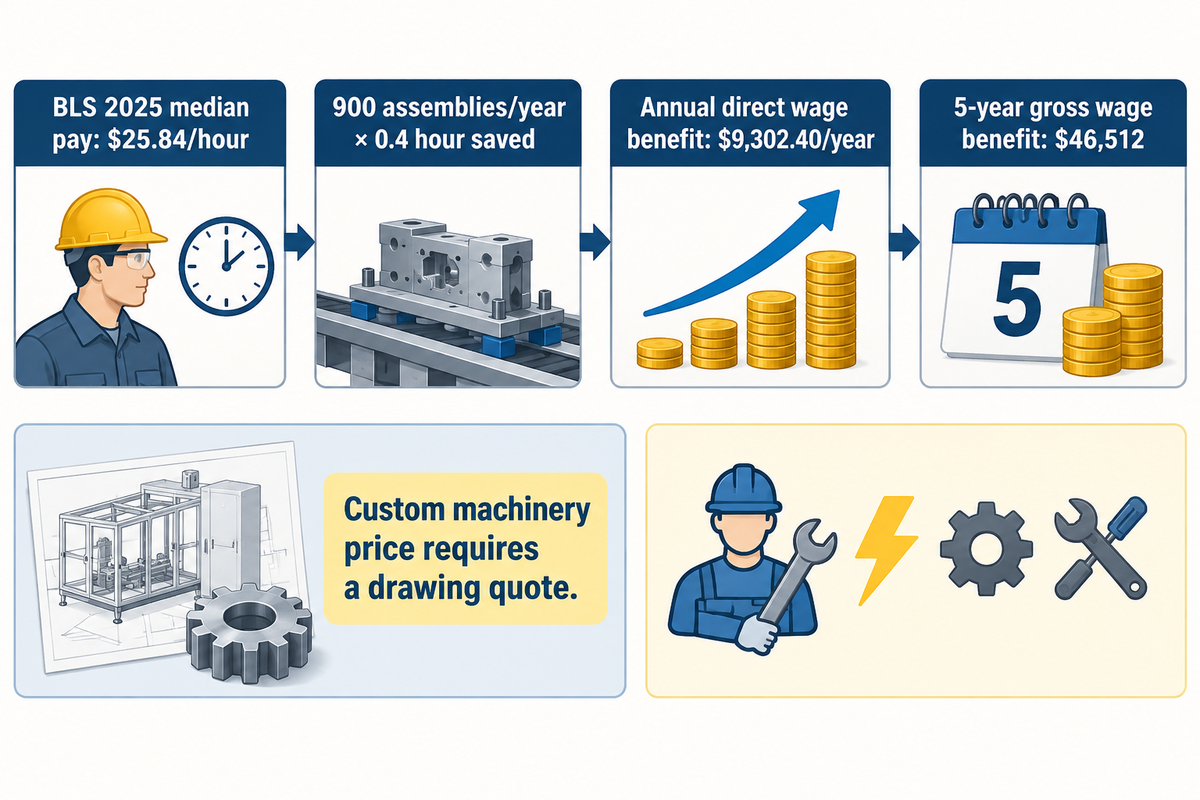
The Fabricator’s 5 tips to increase welding throughput recommends measuring the complete job cycle from material staging to final inspection before requesting equipment prices. Custom structural manipulator cells, synchronized headstock-tailstock sets, and pull-through beam lines are adjusted by stroke, rail length, and tonnage. As a result, machinery price requires a custom quote (需询价) based on your drawings.
To begin testing the limits of affordable investments, use a transparent wage baseline. The US Bureau of Labor Statistics lists $25.84 per hour as 2025 median pay ($53,750 per year) for welders, cutters, solderers, and brazers. The sensitivity table below applies that published $25.84 hourly wage across illustrative shop volumes of 300, 900, and 1,800 structural assemblies per year. It models realized labor savings of 0.2, 0.4, and 0.6 hour per assembly over a 5-year planning horizon. Saving 0.4 hour per assembly across 900 annual assemblies yields 900 × 0.4 × $25.84 = $9,302.40 per year. Over 5 years, that equals $46,512 before deducting installation, energy, and maintenance costs.
| Annual structural assemblies | Realized labor saved per assembly | Annual direct wage benefit | 5-year gross wage benefit |
|---|---|---|---|
| 300 assemblies/year | 0.2 hour/assembly | $1,550.40/year | $7,752 |
| 300 assemblies/year | 0.4 hour/assembly | $3,100.80/year | $15,504 |
| 300 assemblies/year | 0.6 hour/assembly | $4,651.20/year | $23,256 |
| 900 assemblies/year | 0.2 hour/assembly | $4,651.20/year | $23,256 |
| 900 assemblies/year | 0.4 hour/assembly | $9,302.40/year | $46,512 |
| 900 assemblies/year | 0.6 hour/assembly | $13,953.60/year | $69,768 |
| 1,800 assemblies/year | 0.2 hour/assembly | $9,302.40/year | $46,512 |
| 1,800 assemblies/year | 0.4 hour/assembly | $18,604.80/year | $93,024 |
| 1,800 assemblies/year | 0.6 hour/assembly | $27,907.20/year | $139,536 |
Preventing Flange Distortion and Selecting Structural Welding Equipment Suppliers
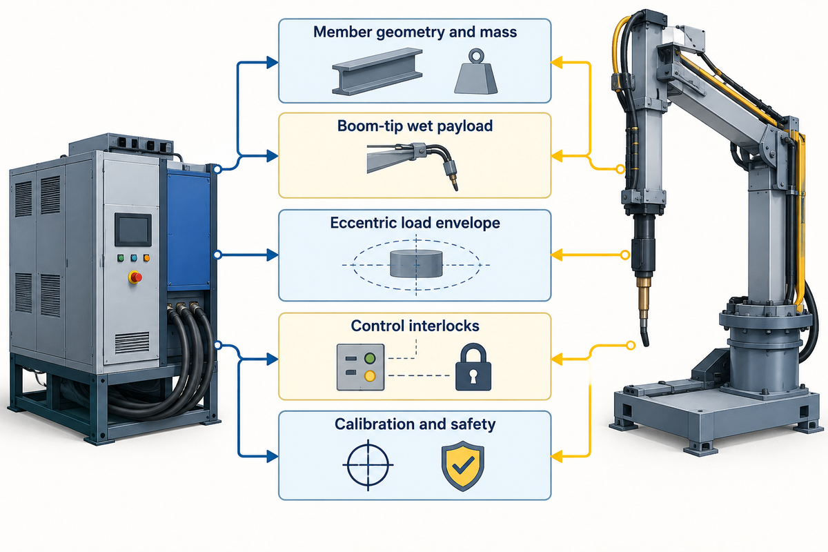
High-deposition structural welding introduces thermal shrinkage and flux-handling risks that must be managed at the workstation level. Addressing web-to-flange distortion, flux overburden defects and multi-vendor interface boundaries before purchase eliminates the risk of commissioning delays when integrating power sources with heavy handling machinery.
In submerged arc stations, flux depth impacts bead geometry and gas escape. The Welder’s flat-position submerged arc welding guide warns that an excessive flux burden causes weld bead distortion and surface pockmarking. Meanwhile, The Fabricator’s review of weld distortion control notes that mechanical conditioning is a tool rather than a cure-all. Shops still pair balanced welding sequences with mechanical roller or hydraulic flange-straightening machines.
Many fabrication plants split the equipment contract when procuring a complete structural station. One plant, for example, may pair an arc power source brand (like Lincoln Electric, ESAB or Miller) with a dedicated handling equipment manufacturer (like RESIZE manipulators, positioners and rotators). Lock down the mechanical and electrical interfaces with both suppliers, and perform Factory Acceptance Testing using the checklist below.
Split-scope structural welding equipment quotation checklist
| Interface parameter | Specification to provide | Why it governs cell uptime | Verification method |
|---|---|---|---|
| Member geometry and mass | Representative beam, column, and truss drawings with fixture mass | Determines vertical reach, floor clearance, and gravity torque | Overlay full rotational sweep and boom reach on bay layout drawings |
| Boom-tip wet payload | Combined mass of weld head, slides, wire reels, cables, and filled flux hopper | Prevents excessive boom droop during long submerged arc passes | Measure vertical deflection at maximum horizontal extension under test load |
| Eccentric load envelope | Center-of-gravity radial offset and axial overhang from positioner table | Protects spindle bearings, tilt gears, and braking drives | Match worst-case assembly moments to published load-offset curves |
| Control interlocks | Start-stop relay logic, travel-speed feedback, and emergency-stop circuit | Synchronizes arc ignition with manipulator or rotator motion | Test dry-contact or fieldbus handshakes during factory acceptance |
| Calibration and safety | Meter verification points, anti-fall vertical lock, and fume/fire controls | Supports AISC, AWS D1.1, ISO 17662, and OSHA shop compliance | Inspect mechanical safety locks and calibration records prior to shipment |
Veelgestelde vragen
Is there a code for structural steel welding, and does it regulate shop welding equipment?
Yes, AWS D1.1/D1.1M governs structural steel welding in the United States, while AISC 207-25 and ISO 17662:2025 set quality and calibration controls for shop equipment.
These standards do not endorse specific machinery brands, but they require equipment capable of holding qualified voltage, amperage, and travel-speed windows across various materials. Under AWS D1.1 and ISO 14732:2025, personnel running mechanized submerged arc manipulators must also hold documented welding operator qualification rather than relying on a machine certificate alone.
What is the difference between a pull-through H-beam welding line and a column-and-boom manipulator cell?
A pull-through H-beam line moves straight beams through fixed frames, whereas a column-and-boom manipulator cell moves the welding head along a rail over stationary or tilted workpieces.
Pull-through lines suit dedicated fabrication bays producing uniform wide-flange rafters and columns at steady monthly tonnage. By contrast, a traveling manipulator paired with floor skids or tilting positioners adapts to deep bridge girders, cambered members, and heavy box columns. It also handles custom structural nodes with minimal fixture changeover time between different project drawings.
Which welding process is best for heavy structural steel beams and columns?
Submerged arc welding is the primary choice for long longitudinal girder fillets and box-column corner seams, while gas-shielded flux-cored arc welding handles stiffeners, clips, and out-of-position joints.
Submerged arc stations use single-wire direct current or tandem direct-current/alternating-current heads to achieve deep penetration and high deposition without open arc radiation. Flux-cored wire feeders using 1/16 in. (1.6 mm) all-position or larger flat-position electrodes give operators reliable welding tools for connection plates and sub-assembly fit-up across the bay.
How do I size a welding positioner or manipulator for structural columns with off-center baseplates?
Size a structural welding positioner by calculating both rotational torque from radial center-of-gravity eccentricity and tilting moment from axial overhang. Include the combined mass of the column, baseplate, corbels, and clamping fixture. Match those moments against the manufacturer’s load-distance curves and check floor swing clearance. For long columns, use a synchronized headstock-tailstock pair, and verify manipulator boom deflection under full wet load.
How do you prevent overhead crane bottlenecks in a structural welding bay?
Equip welding stations with local tilting positioners, turning rolls, or dual parallel fit-up beds served by one rail-traveling manipulator. Allowing operators to orient assemblies into the flat position at the workstation eliminates repeated overhead crane lifts and keeps the arc running while the adjacent bed is staged.
What qualifications do operators need to run automated structural steel welding machines?
Under AWS D1.1 and ISO 14732:2025, personnel who set up or adjust mechanized submerged arc manipulators and automated welding cells must qualify as welding operators. Qualification testing verifies that the operator can set joint tracking, voltage, wire feed speed, travel speed, and flux recovery within the qualified welding procedure specification.
Plan Your Structural Steel Welding Bay Package
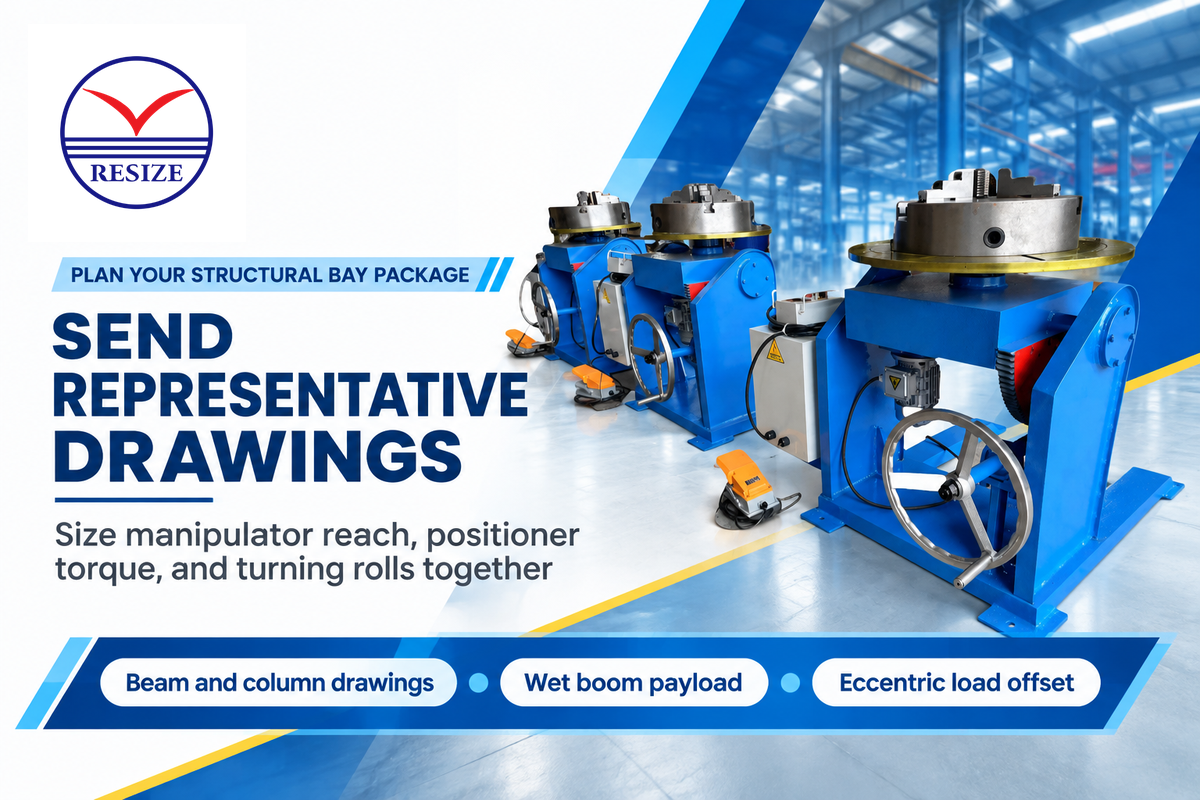
These answers illustrate the need to match up the handling axis with the member geometry, check wet payload reach and eccentric torque with representative drawings, and analyze capital cost against crane-free arc time, prior to placing the equipment order. Send your beam, column or truss drawings to RESIZE to size the manipulator, positioner and rotator package for your fabrication shop.
Related Reading
References & Sources
- OSHA 29 CFR 1910.252 General Welding Requirements
- OSHA 29 CFR 1910.1026 Hexavalent Chromium Standard
- AISC Engineering Journal: Box-Column Electroslag Welding
- STRUCTURE Magazine: Electroslag Welding from Shop to Field
- The Fabricator: Deploying Welding Positioners for Safety and Productivity
- AWS Welding Digest: Best Practices for Handling Heavy Weldments
- UCLA Physics Reference: Calculating Torque Using the Moment Arm
- TWI: Electrode Polarity in Submerged Arc Welding
- TWI: Equipment for Submerged Arc Welding
- The Fabricator: Automating Welding Starts with Asking the Right Questions
- AWS D1.1/D1.1M:2025 Structural Welding Code, Steel
- AISC 207-25 Standard for Certification Programs
- AISC Certified Fabricators Program
- ISO 14732:2025 Qualification of Welding Operators and Weld Setters
- ISO 17662:2025 Calibration, Verification and Validation of Welding Equipment
- University of North Dakota Study: High-Mix, Low-Volume Welding Automation
- The Fabricator: 5 Tips to Increase Welding Throughput
- US Bureau of Labor Statistics: Welders, Cutters, Solderers, and Brazers Pay
- The Welder: Improving Results in Flat-Position Submerged Arc Welding
- The Fabricator: Controlling Weld Distortion