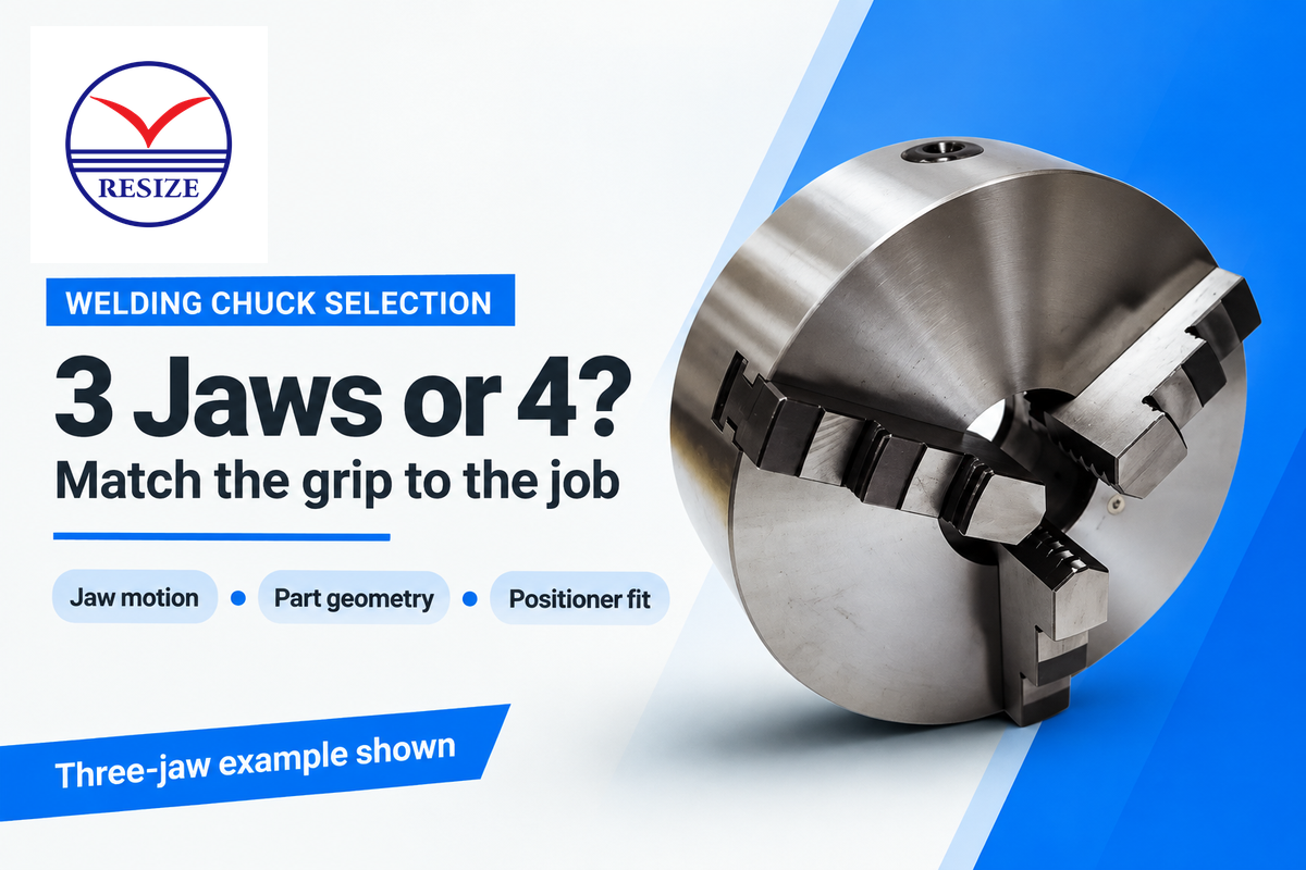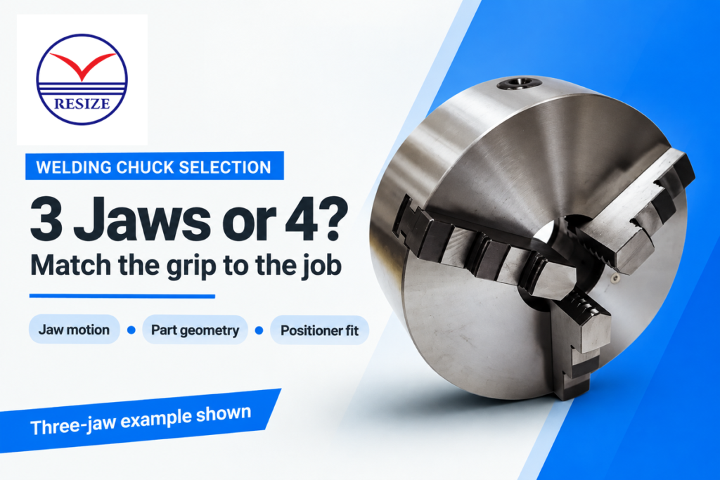
The choice of a 4 jaw vs 3 jaw welding chuck starts with the gripping surface: a three-jaw self-centering design is a practical first choice for repeated round work, while independently adjustable four-jaw designs suit jobs needing unequal jaw positions. Jaw count alone doesn’t determine the load capacity of the chuck. Alignment accuracy isn’t determined by jaw count alone.
A round pipe, a rectangular tube, and a flange with an offset joint present different workholding problems. A useful comparison is how each chuck locates the joint and holds the part through the welding cycle. For basic components and terminology, start with our explanation of a welding chuck.
3-jaw and 4-jaw chucks: the practical differences
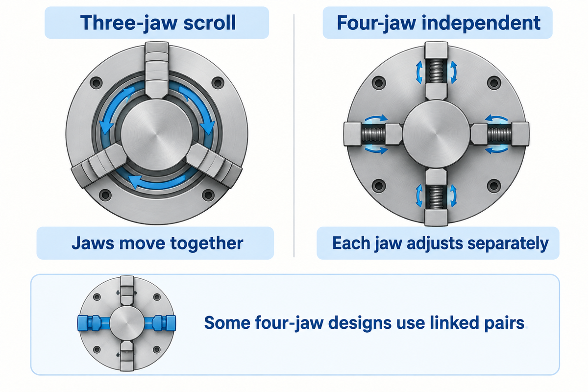
A conventional three-jaw scroll chuck moves its jaws together; a 4-jaw independent chuck lets the operator adjust each jaw separately. With the linked adjustment motion of some four-jaw chucks, the number of jaws doesn’t necessarily establish how the chuck can be used.
的 Open Oregon chapter on chucks describes the familiar lathe arrangement: a scroll synchronizes 3 jaws for round or hex stock, while individual screws position four jaws. While these mechanical principles can help with selection, operating limits for lathe chucks and welding-positioner chucks aren’t always the same.
A useful exception to the standard two-column comparison is found in The Fabricator’s Team Industries positioning case. In this example, opposing jaws move as pairs, and each pair operates independently of the others. Drawings of four jaws, for example, still leave a purchasing decision to make: which jaws move when the operator turns a screw or actuates the clamp?
What are 3 jaw chucks good for?
Three-jaw self-centering chucks are useful for repeat round stock, where the gripping diameter serves as a reference for the weld. Where movement of the jaws is coupled, the number of adjustments is reduced. Still, a shop needs to check seating and joint alignment after loading; centering the outside diameter, for example, doesn’t necessarily center an offset feature or correct an out-of-round tube.
It’s better to use a three jaw chuck for repeatability in a positioning task, rather than to depend on it for correcting variability of incoming workpieces. When comparing three-jaw and four-jaw chucks, the extra adjustment is justified when the task requires unequal contacts.
Choose the jaw arrangement for your workpiece
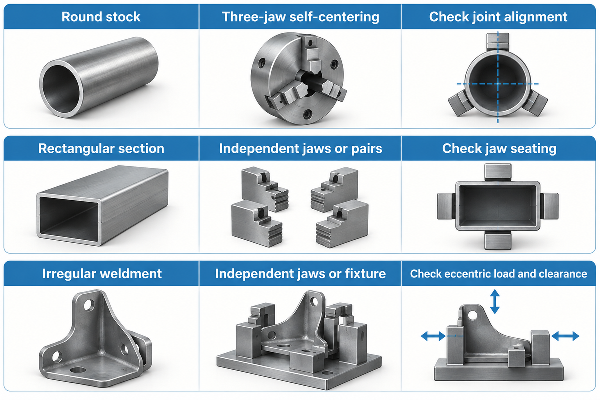
When determining the type of jaw motion, one needs to look at the surfaces that will take up the clamping load. For regular hexagonal and round stock, a conventional three-jaw scroll is appropriate. Unequal opposing dimensions or irregular contact surfaces favor independent adjustment or a dedicated fixture. Nominal opening diameter alone doesn’t indicate whether the jaws will seat securely on the required surfaces.
| Part category and gripping surface | Starting shortlist | What can change the choice? |
|---|---|---|
| Regular hexagonal stock | Conventional three-jaw scroll | Seat on suitable flats; check the actual jaw profile |
| Thin-wall round tube | A supported or shaped-contact setup | Check distortion and holding security together, regardless of jaw count |
| Flange with a usable round gripping land | A compatible self-centering arrangement | Face seating, land depth and access to the joint |
| Round body with an offset weld feature | Independent adjustment or a dedicated fixture | Locate the required weld axis and check the eccentric loading |
| Finished surface vulnerable to jaw marks | Approved shaped or soft contact jaws | Surface protection must preserve adequate grip |
| Round pipe or round bar | Three-jaw self-centering | Ovality, thin walls or a weld axis different from the gripping diameter |
| Square section | Suitable four-jaw linked or independent design | Corner radii, jaw shape and whether all contact faces seat |
| Rectangular section | Independent jaws or suitable independent opposing pairs | Unequal width and height prevent an equal-travel assumption |
| Irregular weldment | Independent jaws or dedicated fixture | Limited contact, eccentric load, clearance and the required weld axis |
Consider a fabrication shop changing from a round tube to a rectangular bracket assembly. The buyer locates a four-jaw scroll model where the opening appears large enough. Nevertheless, the opposing faces of the bracket are at different distances from the desired rotation axis. Moving all the jaws inward by the same amount won’t necessarily seat all the contacts. An independent design may solve the locating problem. However, the projecting bracket creates a second problem: it rotates off-center. The plant manager gains flexibility only if the fixture also clears the torch and stays within the positioner’s allowed load geometry. Quality staff need to define the weld-axis reference on the drawing before procurement compares chuck sizes.
Thin-wall tube needs a different grip strategy
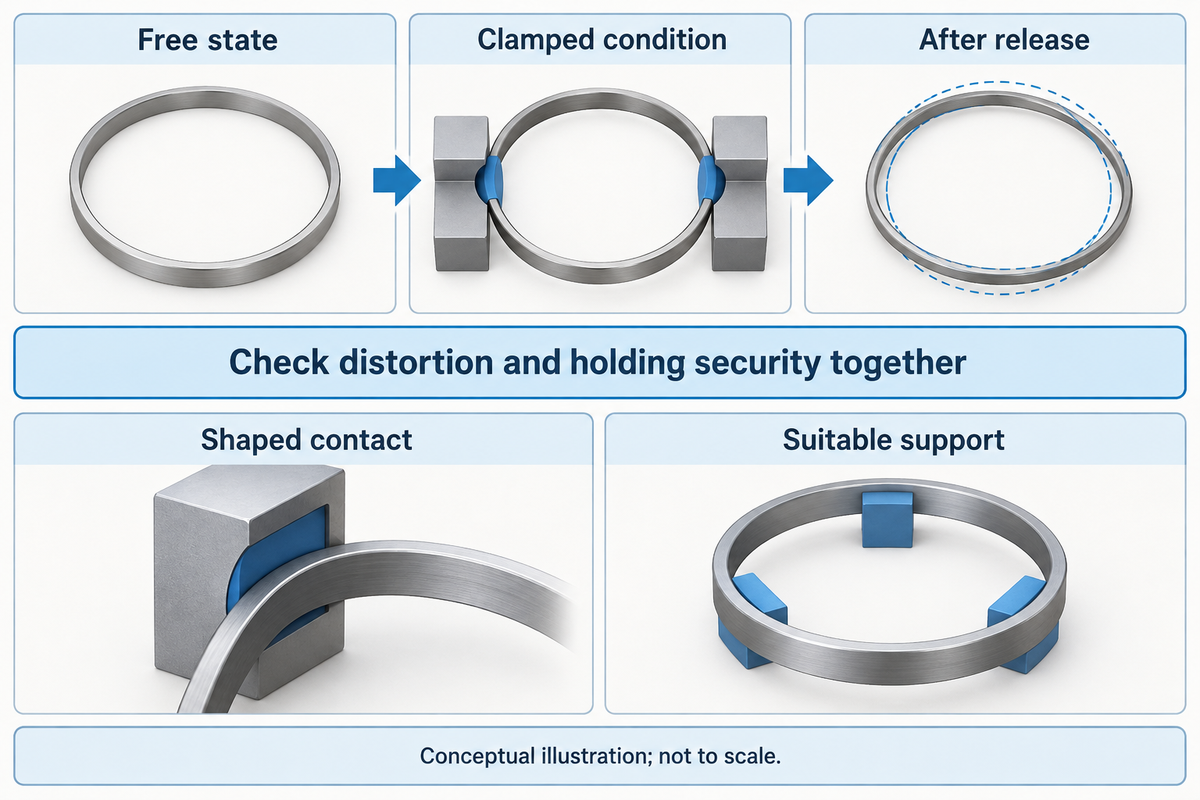
Holding force in thin-wall tubes can be problematic as it may deform the tube beyond what’s acceptable. In this case, contact area and support may be more important than adding an extra jaw. Inspect the part both clamped and unclamped because a problem may become apparent only when the part is released, due to springback. There’s no universal wall thickness cutoff for what’s acceptable.
The DefCon research description from Leibniz University Hannover discusses how thin-walled turning workpieces get deformed by clamping forces and how their shape changes when released. This is research on machining but may be helpful for a welding case study: does the chuck temporarily deform the tube and hold it in that shape, or is it holding the tube in its intended shape?
Imagine a short stainless sleeve that looks round when clamped but changes shape after release. Switching from three jaws to four without changing the narrow contact faces still leaves an unresolved question. The first trial should compare the free state part to its clamped condition and the completed weldment. A jaw profile that follows the tube, or a suitable supporting arrangement, may be more useful than extra tightening. Quality staff need a drawing-based acceptance criterion; the operator needs an approved clamping setup that still resists movement. If a backing support is considered, its removal, weld access and interaction with the welding process belong in that trial too.
What is the advantage of a 6 jaw chuck?
A six-jaw chuck offers more contact locations around a suitable round part, which can help a properly designed setup distribute its grip. A tight grip can still distort the part, even with six jaws. Jaw conformity and force still apply, and a chuck needs explicit approval for the welding application to transfer its performance claims to that job.
Shaped soft jaws, suitable collets or a dedicated holder are also options. American Machinist’s No-Squeeze Workholding covers compliant contact strategies for distortion-sensitive machining. The important takeaway is to match the contact to the part, rather than considering one jaw count as a remedy.
Self-centering does not mean zero runout
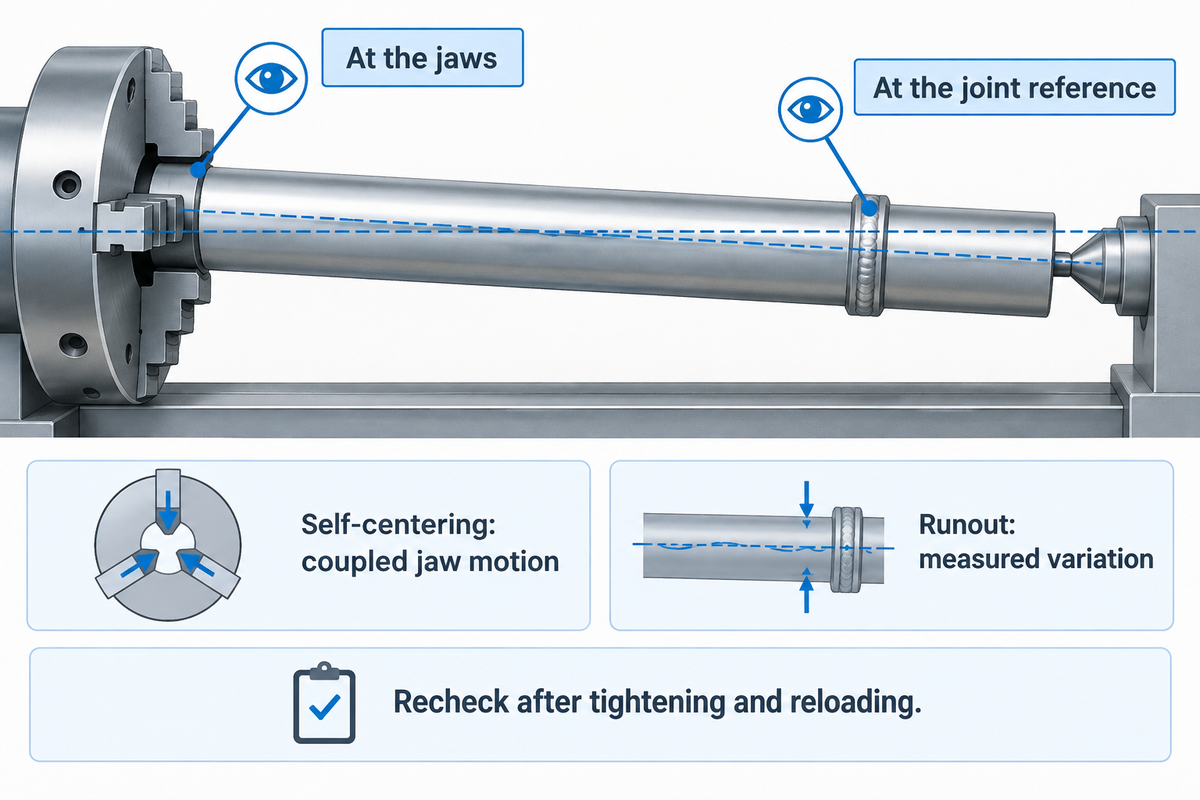
Self-centering describes coupled jaw motion, while runout describes measured variation during rotation. A centered gripping surface can coexist with an offset or tilted weld joint. Check the relevant joint reference and, on a longer part, another axial location. Use the drawing and the requirements of the welding process to decide acceptance, rather than borrowing a general machinist’s tolerance.
的 public-college OpenWA workholding setup chapter separates end runout from concentricity at the chuck jaws and suggests rechecking after tightening. The examples in the chapter indicate that a three-jaw setup can yield useful accuracy. The distinction isn’t precision vs. bad quality.
- Define the reference. Identify the surface or joint axis that controls torch position.
- Seat and clamp the part. Use the approved jaw positions, contacts and clamping method.
- Measure the relevant locations. Follow the equipment’s safe setup procedure and compare the readings with the job requirements.
- Repeat after reloading. Record whether the next workpiece returns to an acceptable position without extra adjustment.
A useful record for an automated circumferential weld includes the amount of variation in the joint, the seating condition, and the adjustment needed after each reload. This makes the tradeoff visible: independent jaws offer correction, while a suitable self-centering setup can reduce routine adjustment. Neither removes the need for a sound mounting plate and an undamaged spindle interface.
Compare chuck prices and setup costs
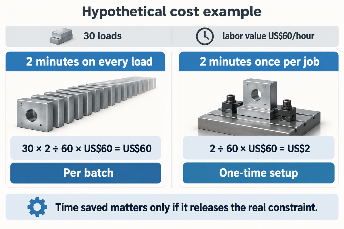
Consider the chuck package and the time taken to load acceptable parts. A bare chuck price can exclude the adapter, special jaws, and installation. Separate one-time setup from adjustment repeated on every part; otherwise, small batches and production runs can appear to justify the same purchase, when their labor costs can vary significantly.
Woodward Fab listed its WFWPC6-3 at US$269 on October 27, 2026, with both inside- and outside-diameter clamping jaws included. That price reflects a retail configuration and doesn’t suggest a general three-jaw versus four-jaw price gap. Obtain dated quotes with the same mounting requirements and inclusions; prices and availability can change.
| Input | Illustrative value | Use your shop’s figure |
|---|---|---|
| Loads per batch | 30 | Count actual reloads, including rework |
| Extra adjustment per load | 2 minutes | Time both suitable setups on the same job |
| Labor value | US$60 per hour | Use the agreed labor-cost basis |
| Extra adjustment labor value | US$60 per batch | 30 × 2 ÷ 60 × US$60 |
In this hypothetical batch, two extra minutes on each of thirty loads consume one hour. At the assumed labor rate, the difference is US$60 per batch. But if those two minutes occur only once when setting up the job, the value is just US$2. The distinction changes the purchase case. Finance should also ask what happens to the released hour: does it increase saleable output, avoid overtime or simply create waiting time? The plant manager should time lifting, alignment and inspection separately. A quicker chuck pays back only through a useful reduction in the actual constraint, while rejected parts can erase an apparent setup saving.
Keep the setup repeatable between jobs
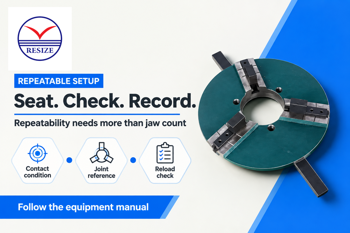
Repeatable setup is possible with consistent seating and contact surfaces together with an approved clamping procedure. Contamination, worn jaws or a change in the part geometry can adversely affect alignment. For repetitive jobs, record the jaw arrangement and reference surfaces. Also, check the loaded part after a change. Remembering a chuck key position isn’t a measurement.
Clean the locating faces, jaw slots, and contact areas as directed by the chuck manual. Where the design permits inspection, check the back of the jaws and the contact areas for spatter or other damage that prevents full seating. Lubricate the machine as directed by the manufacturer; don’t substitute a generic hydraulic-lathe maintenance interval for this machine. See our welding chuck guide for further information.
For servicing that exposes workers to unexpected startup or stored energy, apply the relevant energy-control procedure. OSHA 29 CFR 1910.147 distinguishes energy-isolating devices from control push buttons. Normal production and minor servicing have specific application rules; a stop command alone shouldn’t be treated as physical energy isolation.
Setup Bottleneck Map
| Observed delay | Check before buying | Decision owner |
|---|---|---|
| Repeated centering | Reload variation and whether the chosen datum matches the joint | Quality and production |
| Slow lifting or awkward loading | Handling access and fixture mass | Plant manager |
| Torch repositioning | Jaw projection, joint access and work envelope | Welding engineer |
| Time saved but no extra output | The next production constraint and overtime avoided | Finance and production |
Where to buy a compatible welding chuck
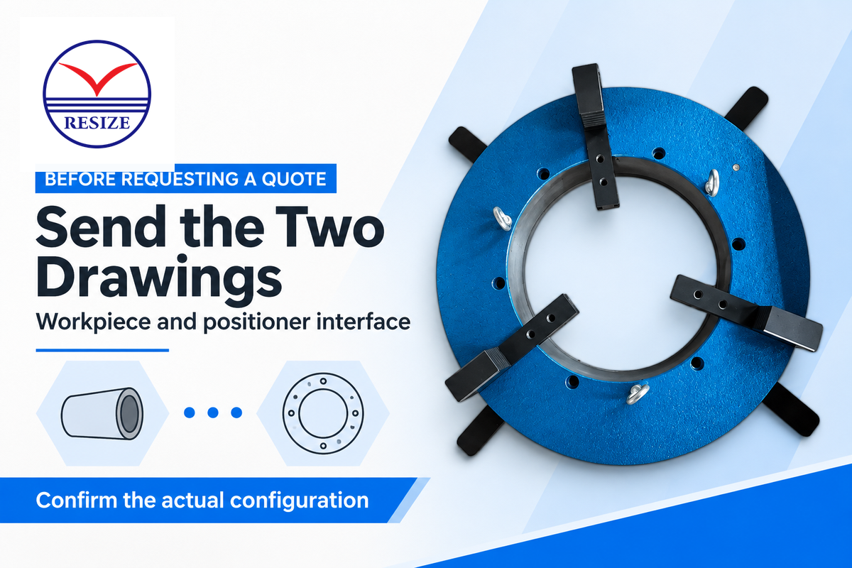
Don’t purchase a machine where the supplier isn’t able to identify the jaw mechanism. A supplier that can match the drawing to the actual positioner can also define the range and limits, gripping jaws, and replacement parts. A label that states heavy-duty provides less information than a drawing and a specific application.
Send the supplier the part drawing, gripping surface, material, min/max dimensions, mass of workpiece, and intended orientation. Also send the weld location and projected features. The supplier can then tell the difference between a standard chuck and a job requiring custom jaws, an adapter or a separate fixture. Discuss a matching welding chuck configuration with RESIZE using those details.
Keep a standards reference separate from a claim of product certification. ISO’s catalogue lists ISO 16156:2004 as current, while ISO/AWI 16156 is under development. The presence of these machine-tool workholding documents on a quotation does not mean a particular welding chuck or workholding system would comply.
Match the chuck to your welding positioner
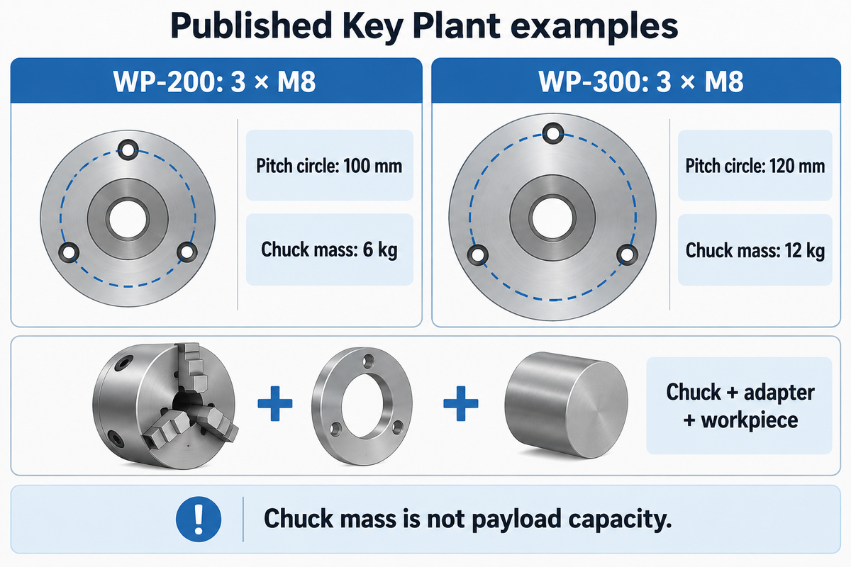
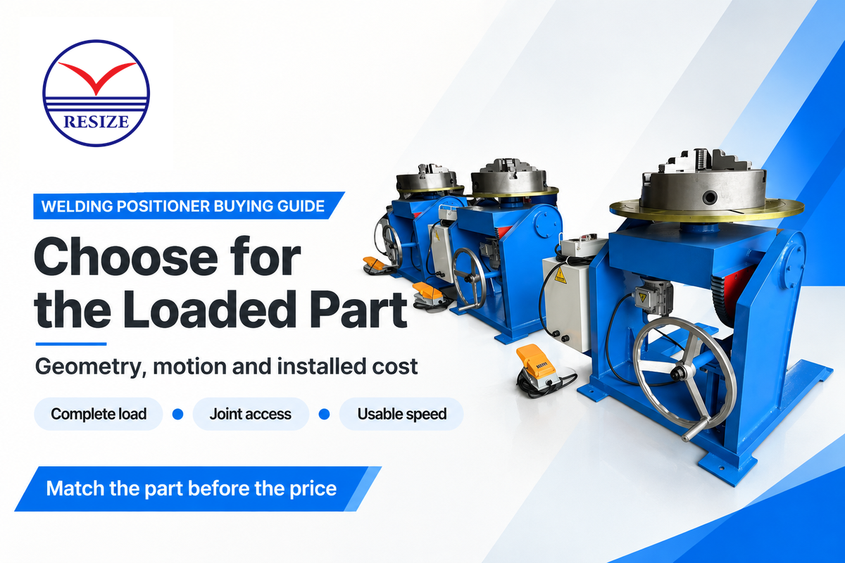
Chuck compatibility requires a matching locating interface and a positioner that supports the rotating assembly. Check the chuck, adapter and workpiece together, including center-of-gravity position and projected envelope. A nominal load label or bolt count leaves out important conditions, especially if an irregular part places mass off-axis.
A concrete mounting example is Key Plant’s published WP-200 and WP-300 data: both list three M8 bolts, but their pitch-circle diameters are 100 mm and 120 mm, respectively. The same page lists chuck masses of 6 kg and 12 kg. Before a customer adds an adapter or loads a workpiece, these differences are significant.
Can this chuck fit other brand welding positioners?
As long as the complete mating interface and the operating limits are compatible, a chuck can fit a different brand’s positioner. Analyze the locating register or pilot, mounting face, bolt pattern, fastener thread size and engagement, bore clearance and adapter geometry. Obtain confirmation of the complete assembled design; matching three bolt holes doesn’t establish correct alignment or the capacity to safely support the load.
The Welder’s Positioner guidance describes why various fixtures add both weight and distance from the mounting face. Consider the combined loading and the specific welding positioner’s rating for the maximum intended tilt and rotation. A larger chuck doesn’t automatically allow the positioner to hold heavier workpieces.
Check the full sweep of the workpiece and projecting jaws, along with the equipment instructions for allowed rotational speed and unbalance constraints. Keep personnel outside of hazard zones. See OSHA 29 CFR 1910.212 for guidance in addressing exposure to machinery hazards, which exist with rotating parts, and guarding of nip points. Low speed doesn’t eliminate hazards. For the rotating equipment side of the system, see the welding turntable overview.
The return path for welding current also requires an intentional design. Protective grounding of the machine frame is different. Where a fixture regularly carries welding return current, OSHA states:
“joints shall be bonded or provided with adequate current collecting devices.”
OSHA, 29 CFR 1910.254(c)(2)(iv), accessed October 2026
Use the equipment’s approved current collection arrangement. Do not assume that a mechanical mounting connection makes every possible current path suitable.
Frequently asked questions
Are there significant quality differences in 4-jaw chucks?
Four-jaw chuck quality varies with the mechanism, jaw fit, materials and documented operating limits.
Will using Soft Jaws fix the inaccuracy of a 3-jaw chuck?
Soft jaws can improve contact on a suitable part, but they cannot correct every source of alignment error.
Can I use thin copper shims or paper under one of the jaws on a 3-jaw chuck to fix the runout?
Improvised asymmetric packing should not be used as a runout fix in a rotating welding setup.
What is a 2 jaw chuck used for?
A two-jaw chuck grips suitable components between opposing contacts, often with a part-specific jaw profile.
What is the production lead-time for custom chucks?
Custom chuck lead time depends on the approved design, supplied components and agreed acceptance work.
Start with three-jaw self-centering for repeat round work and independent adjustment for unequal contacts. Make the final choice on verified grip, joint alignment, installed fit and measured loading time.
Before requesting a chuck, put the workpiece drawing beside the positioner interface drawing. Mark the gripping surface and weld axis, then record the batch size and current loading delay. Those details give RESIZE a practical basis for discussing standard jaws, independent adjustment or a dedicated fixture for your job.
How this chuck comparison was prepared
This comparison draws on public workholding education, published research and supplier listings checked in October 2026. The mechanism table is a selection aid, and the cost sheet uses stated hypothetical inputs. Neither replaces the operating instructions for a particular welding chuck and positioner. RESIZE hasn’t supplied private test results for the examples used here.
參考文獻和來源
- Manufacturing Processes 4–5: Chucks Open Oregon.
- Lathe workholding setup OpenWA, Micky R. Jennings, Wenatchee Valley College.
- Deformation control for thin-walled workpieces IFW, Leibniz University Hannover, 2023.
- Weld positioning at Team Industries The Fabricator.
- 5 things welders need to know about weld positioners The Welder.
- No-Squeeze Workholding American Machinist, 2007.
- ISO 16156:2004 和 ISO/AWI 16156 development project ISO catalogue.
- 29 CFR 1910.254, 29 CFR 1910.212 和 29 CFR 1910.147 OSHA.