By GW, RESIZE Welding Automation Engineering Team (Updated November 2026)
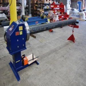
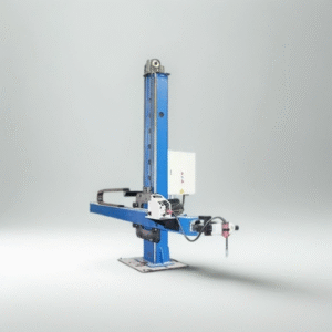
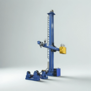
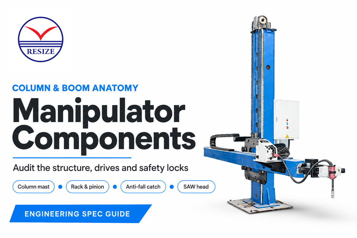
The six load-bearing and motion assemblies that position a mechanized welding head over heavy workpieces are known as welding manipulator components. These include the base chassis or rail trolley, the 360 degree slewing ring, and the vertical column mast with counterweight. The frame is completed by the saddle and crossbeam guideways, axis drives, and boom-tip torch carrier. Representative examples below cover strokes from 1,000 to 9,000 mm and rated loads from 150 to 1,000 kg across various model classes.
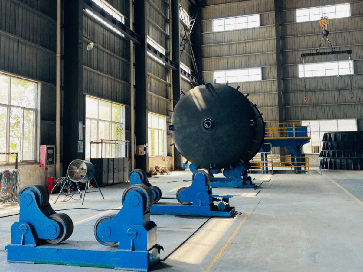
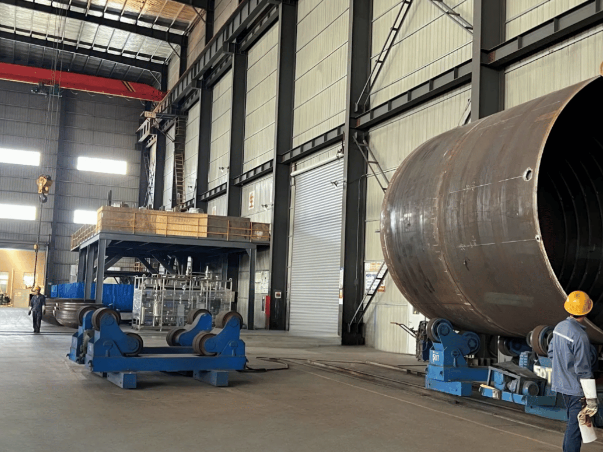
In Catalog stroke figures, there’s always a difference in net torch reach on the fabrication floor. In representative setups, self-aligning turning rolls lift a cylindrical shell, 550 to 850 mm above the fabrication floor slab. A submerged arc welding head, cross slide, and flux nozzle hang 300 to 450 mm below the boom. The boom payload includes the welding head, cross slide, wire reels, and other equipment, and determines the bending moment at the intended working reach.
Welding manipulator components transfer overhung torch loads through precision crossbeam guideways, and are anchored to a column mast at the base. The boom payload consists of the welding head, cross slide, mounted wire reels, full flux hopper, and equipment carried by the boom. Their position determines the bending moment at the working reach. Mechanical anti-fall arrestors and drive speeds of the boom from 50 to 3,048 mm/min are also verified by engineers.
Key Engineering Takeaways
- A catalog 454 kg (1,000 lb) static rating or 150 to 600 kg standard boom chart must cover the complete mounted submerged arc package. A filled 50 to 100 L heated flux hopper adds 50 to 100 kg, and suspended drag-chain cables add 40 to 80 kg of hanging drag load.
- Medium-duty booms such as the Koike Aronson Cricket-II use a ball screw lifting at 20 IPM (508 mm/min) for 227 kg loads. Workshop and heavy vessel manipulators use counterweight chain hoists or rack-and-pinion elevation drives.
- If hoist chain tension drops or a chain parts, a spring-loaded cam or pawl arrestor engages the vertical safety rack on the column to catch the saddle carriage. Because a slack-chain pawl does not trip if a gearbox fails while the chain stays tensioned, protecting against gearbox failure requires an independent load-path brake or rack-and-pinion arrestor.
- The welding work-return connection carries welding current back to the power source and is separate from protective frame grounding. Its current and duty-cycle ratings must accommodate the welding load; rotating workpieces can use a rotary current collector that bypasses bearings.
What Are the Core Welding Manipulator Components in a Column and Boom Assembly?
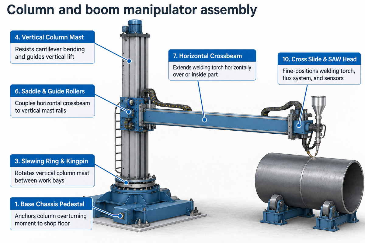
A column and boom assembly consists of six electrical and mechanical subsystems, including the base chassis, 360-degree slewing ring, vertical column mast with counterweight, saddle and crossbeam guideways, axis drives, and boom-tip carriage. Industrial strokes range from 1,000 to 4,000 mm on medium frames and 8,000 to 9,000 mm on heavy vessel booms.
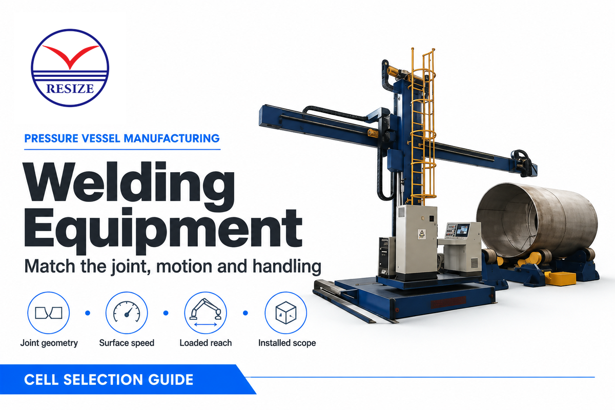
In pressure vessel and structural fabrication, a column and boom welding manipulator acts as the primary automated welding assistant machine. An articulated welding robot moves a light torch across short automotive fixtures. In contrast, a column and boom moves heads and multi-process welding equipment along long cylindrical shells. AWS A3.0 and ANSI/AWS Z49.1 define terms and safety guidelines for welding, cutting and allied processes. Meanwhile, the manipulator motion system controls the extension and travel speed of the electrode along the weld joint.
Published stroke, boom-tip load, and speed ranges come from specific manufacturer series datasheets (AMET XM Series, Koike Aronson Cricket-II, Irizar WM Series, and RESIZE LH Series). Those specifications apply only to each respective frame class. AMET XM Series manipulators provide vertical and horizontal strokes of 1, 1.2, 1.5, 2, 2.5, 3, and 4 m (3.2 to 13.1 ft). Those frames support end-of-boom loads from 150 to 600 kg (330 to 1,300 lbs). Medium-duty units like the Koike Aronson Cricket-II carry 227 kg (500 lbs). Extra-heavy booms like the Irizar WM 9060 reach 9 m vertical by 6 m horizontal stroke, while the RESIZE LH-8080 reaches 8,000 by 8,000 mm.

| Subsystem / Component | Primary Mechanical Role | Published Industrial Spec Range | Primary Failure Mode if Undersized |
|---|---|---|---|
| 1. Base Chassis Pedestal | Anchors column overturning moment to shop floor | Machined steel baseplate bolted to concrete footing | Anchor pull-out or base rocking under overturning moment |
| 2. Motorized Rail Trolley | Travels full manipulator along floor track rails | AC gearmotor rail drive with wipers and track clamps | Track skewing or braking drift between vessel courses |
| 3. Slewing Ring & Kingpin | Rotates vertical column mast between work bays | 360-degree manual or motorized rotation with lock | Angular boom tip whip or stray-current bearing pitting |
| 4. Vertical Column Mast | Resists cantilever bending and guides vertical lift | 1,000 to 9,000 mm vertical stroke; box-section steel | Out-of-plumb column lean increasing lever arm moment |
| 5. Internal Counterweight | Balances dead weight of saddle, boom, and weld head | Guided counterweight inside column linked by roller chain | Hoist motor thermal trip and rapid chain elongation |
| 6. Saddle & Guide Rollers | Couples horizontal crossbeam to vertical mast rails | Preloaded eccentric CAM rollers on milled ways | Play above 0.5 mm causing vertical torch nodding |
| 7. Horizontal Crossbeam | Extends welding torch horizontally over or inside part | 1,000 to 8,000 mm horizontal stroke; 150 to 1,000 kg load | Downward boom-tip deflection under full-reach rated load |
| 8. Anti-Fall Safety Lock | Catches vertical carriage if hoist chain tension drops | Spring-loaded pawl engaging vertical column safety rack | Uncontrolled vertical boom drop if hoist chain parts |
| 9. Elevation & Boom Drives | Drives Z-axis lift and stepless X-axis seam travel | Listed configurations: lift 508 to 1,200 mm/min; boom 50 to 3,048 mm/min | Low-speed stick-slip ripples on longitudinal weld beads |
| 10. Cross Slide & SAW Head | Fine-positions welding torch, flux system, and sensors | 100×100 or 250×250 mm slide at 1,000 mm/min; 50–100 L flux | 300 to 450 mm vertical hang-down colliding with shell |
Place and size each assembly to fabricate the shape and size of the weldment. This configuration allows the boom to reach external longitudinal seams and internal circular girth joints without re-chocking the vessel. In upstream plate preparation bays, thermal or mechanical tables handle cutting plates to flat blank dimensions. A bevel milling machine then machines weld joint bevels before shell rolling. In the assembly bay, engineers map the position of the workpiece, relative to the manipulator column base.
How Do the Chassis Base, Turning Mechanism, and Travel Trolley Support Heavy Machinery?
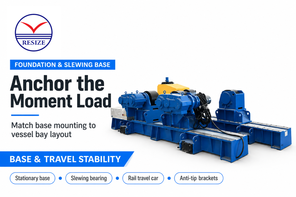
A loaded crossbeam extending between 1,000 to 8,000 mm generates an overturning moment which is countered by the base of the chassis, the slewing ring, and the motorized rail travel trolley. A pedestal is bolted to a concrete foundation. A motorized rail travel trolley is free to move on a floor track with a mechanical rail clamp.
A base footprint of the horizontal boom resists a cantilever moment when the crane is fully extended with a load of 150 to 600 kg. Anchor tension and rail-wheel reactions are dependent on the overturning moment, support spacing, weight, and center of gravity of the complete manipulator. Modular columns and rail carriages in ESAB AB Patent SE532775C2 classify heavy welding manipulators as rail-mounted carriages (B23K37/0211). The same patent discloses extensible boom arms (B25J18/025) to limit structural deflection across a large weld.
Stationary Floor-Anchored Base vs Motorized Rail Travel Trolley
A stationary floor-anchored base welds steel gussets to a machined baseplate that bolts into a reinforced concrete foundation. The anchors may pull-out during repetitive moments exerted by the boom slewing. Column foundations, in conjunction with a group of anchors, resist an overturning moment, and anchor tension increases with a decrease in the lever arm. Bolt-on base outriggers increase the support footprint and resistance to overturning.
When one automatic welding machine has to serve multiple vessel beds, a motorized rail travel car (trolley) replaces the fixed pedestal. A four-wheel steel trolley runs on machined shop rails driven by an AC gear motor. Spring loaded rail wipers remove abrasive submerged arc flux and mechanical rail clamps lock the trolley during welding. Automated rail travel creates collision and crushing hazards. Positive travel limits and guarding and protective devices discussed in the OSHA Technical Manual Section IV, Chapter 4 restrict access to these hazards.
360-Degree Slewing Bearing and Column Turning Lock Mechanisms
On the AMET XM and RESIZE LH models, the column employs a kingpin or slewing ring to allow 360 degrees of rotation. Manual or pneumatic lock brakes secure the column prior to arc ignition. While the column is rotated 90 or 180 degrees, one boom welding manipulator welds a vessel on roller bed A. Overhead cranes are utilized on roller bed B.
Shop-Floor Field Scenario (Out-of-Plumb Slewing Drift): A millwright crew was installing a pipe spool and shimmed a 4,000 mm column base out 0.4 degrees. Structural machinists point out that loading the boom bends both the boom and the column outward. Deflection increases the lever arm, and any offset from the vertical creates a gravity bending moment about the slewing axis. The operator released the manual slewing brake with a 420 kg submerged arc head at 3.5 m reach. Immediately the boom swung toward the low side of the pad, and pulled the torch 18 mm from the pipe bevel. Leveling the slewing ring mounting flange to the horizontal plane, and adding a self-locking worm-gear slewing drive stopped the drift.
Why Do Column Mast Stiffness, Boom Deflection Limits, and Anti-Fall Locks Govern Weld Quality?
Column mast stiffness, roller guideway preload, and mechanical anti-fall locks govern welding quality by holding electrode stick-out and joint alignment steady across multi-meter strokes. Welded box-section cross-beams limit downward tip deflection at full extension under rated load. Spring-loaded anti-fall pawls engage a vertical column safety rack to catch the saddle carriage if the hoist chain tension drops.
Manufacturers construct heavy column masts and cross-beams from welded rectangular box sections reinforced with stiffeners. For columns and booms treated by furnace stress relief after welding, the treatment reduces residual stresses and the risk of later guideway distortion. Post-weld stress relief improves dimensional stability across the machine’s service life. Eccentric CAM bearing rollers in the roller frame are convenient for maintenance. Guideway clearance is taken up without disassembling the beam by external adjustment of the rollers.
“D1.1 is commonly applied to structural steel projects. It is intended for load-bearing steel applications rather than consumer products like appliances and is often used by OEMs for designing and fabricating skids, modules, and equipment.”
What Crossbeam Deflection and Boom-Tip Load Capacity Should Engineers Verify for Submerged Arc Welding?
Engineers verify boom tip loading capacity by adding up the complete submerged arc welding payload. That total includes the head, cross slides, wire reels, a flux filled hopper, cables, operator platform, and anything else added to the boom and must stay within the machine’s load chart at full reach. Aubrik reports tip deflection figures of 1.0 to 1.5 mm for heavy duty column-boom manipulators. Engineers also verify straightness of the guideway in the working stroke.
Buyers must separate three accuracy metrics on manufacturer datasheets: static cantilever droop under dead weight, horizontal guideway travel straightness, and dynamic seam-tracking deviation during actual welding. A catalog table may list a flat 454 kg (1,000 lb) static load across several boom sizes, or 150 to 600 kg on AMET XM systems. However, adding a 50 to 100 L heated flux hopper (50 to 100 kg filled), a 5 HP vacuum separator, and dual wire reels increases the mounted load. Including motorized cross slides, suspended drag-chain cables (40 to 80 kg), and an operator platform pushes extra-heavy tandem submerged arc packages toward 600 to 1,000 kg class columns. On AMET XM booms, maximum lifting capacity equals the rated boom capacity plus an extra 50 kg (110 lbs). That extra 50 kg allowance applies only when auxiliary weight mounts on the opposite rear end of the boom.
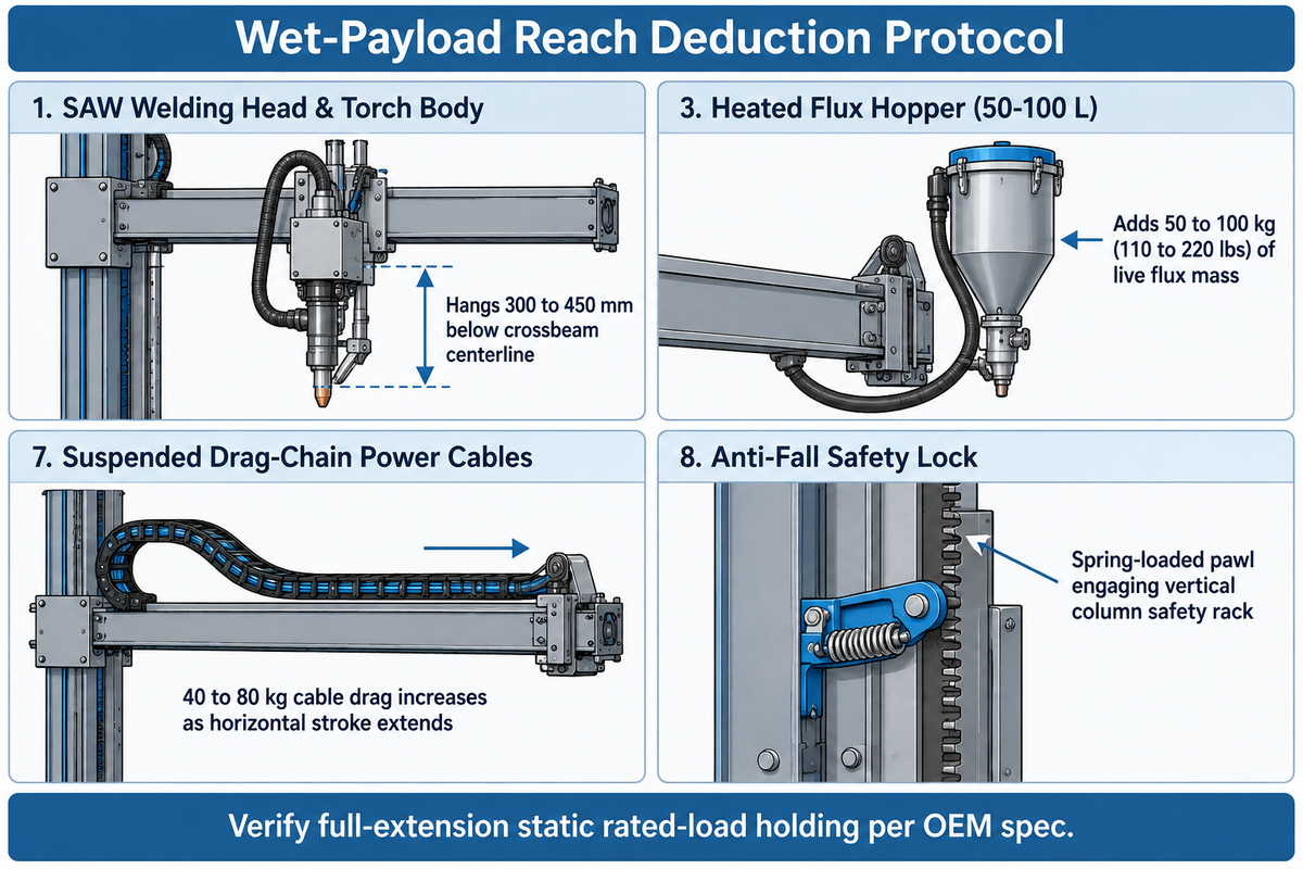
Wet-Payload Reach Deduction Protocol
The Wet-Payload Reach Deduction Protocol is a four step clearance check that subtracts bed elevation of roller and torch hang-down from the stroke.
Worked Engineering Calculation (Net Stroke vs Catalog Stroke): Nominal catalog horizontal and vertical stroke figures don’t equal net torch reach because turning roll bed height (550 to 850 mm), torch hang-down (300 to 450 mm), and column base standoff reduce effective clearance. Consider the assumed inputs for a vessel shop sizing a manipulator (see our column and boom welding manipulator sizing guide). The vessel outside diameter is 3,200 mm, and the self-aligning turning roll bed elevation is 650 mm. The submerged arc torch, cross-slide, and flux nozzle hang-down is 350 mm, minimum saddle height (Hmin) is 700 mm, and base horizontal standoff is 500 mm. To clear the 12 o’clock seam, required maximum boom height is Hmax_required = 650 mm + 3,200 mm + 350 mm = 4,200 mm. Subtracting Hmin (4,200 mm – 700 mm) gives a required vertical stroke (Sv) of 3,500 mm. With a 500 mm horizontal standoff and a 3,500 mm shell length, the far end is 4,000 mm from the stated reference point (3,500 mm + 500 mm = 4,000 mm). That calculation sizes geometric clearance; it doesn’t replace an anchor-bolt bending moment check.
| Boom-Tip Payload Item / Deduction Factor | Single-Wire SAW Package | Heavy Tandem SAW + Operator Seat | Mechanical & Reach Impact |
|---|---|---|---|
| 1. SAW Welding Head & Torch Body | Single-wire torch assembly | Twin-wire / tandem torch assembly | Hangs 300 to 450 mm below crossbeam centerline |
| 2. Wire Feeders & Loaded Wire Coils | Single wire spool and drive | Dual wire reels and straighteners | Shifts center of gravity forward unless rear-mounted |
| 3. Heated Flux Hopper (50–100 L) | 50 kg filled hopper | 100 kg filled hopper | Adds 50 to 100 kg (110 to 220 lbs) of live flux mass |
| 4. Vacuum Flux Recovery Separator (5 HP) | Compact primary separator | 5 HP cyclone separator unit | Check unit weight against the 50 kg AMET XM rear-load allowance |
| 5. Motorized XY Cross Slides | 100×100 mm (±50 mm) slide | 250×250 mm (±125 mm) slide | Fine adjustment at 1,000 mm/min ahead of boom nose |
| 6. Laser or Tactile Seam Tracker & AVC | Tactile probe + AVC slide | Laser camera + AVC slide | Requires low torsional boom twist for optical sensor alignment |
| 7. Suspended Drag-Chain Power Cables | 40 kg hanging drag load | 80 kg hanging drag load | 40 to 80 kg cable drag increases as horizontal stroke extends |
| 8. Operator Seat & Platform Cage | Not applicable (floor pendant) | Boom-mounted operator seat | Requires personnel-rated platform design and mechanical arrestor |
| 9. Typical Rated Boom-Tip Load Class | 150 to 454 kg (330 to 1,000 lbs) | 600 to 1,000 kg extra-heavy class | Verify full-extension static rated-load holding per OEM spec |
How Does a Mechanical Anti-Fall Safety Device Prevent Vertical Boom Drop if the Lift Chain Fails?
In order to prevent vertical boom drop, a mechanical anti-fall safety device connects a spring-loaded cam or pawl to the hoist chain anchor on the saddle carriage. If the hoist chain becomes slack or breaks, the spring on the pawl drives it to engage with the vertical column safety rack. However, a slack-chain pawl won’t trip if a gearbox fails while the chain remains tensioned, and an upstream motor brake can’t hold a broken downstream chain. Therefore, a protective measure against gearbox failure requires an independent rack-and-pinion brake or a secondary load-path arrestor.
A motor brake catches the carriage via an intact lift transmission, and a mechanical arrestor stops the carriage when engaged; travel limits prevent overtravel and counterweights reduce lift demand.
- In normal hoist tension, the duplex roller chain holds a spring-loaded pawl away from the vertical column rack. If chain tension is dropped, or the chain breaks, the pawl engages the vertical column rack to catch the carriage. A slack-chain pawl alone won’t trip if a gearbox upstream of the failure fails while the chain remains tensioned.
- A vertical lift drive couples a gear reducer to a spring-applied electromagnet disk brake on the AC motor shaft. Any shop power loss locks the motor shaft immediately through an intact transmission. An upstream motor brake, however, can’t arrest free-fall if a downstream lift chain breaks.
- A balancing counterweight is mounted inside the column and provides part of the static mass of the saddle to minimize hoist torque. Lower and upper electrical limit switches stop the hoist prior to contact with mechanical stops.
How Do Rack-and-Pinion Elevation and VFD vs Servo Drive Systems Compare on a Boom Manipulator?
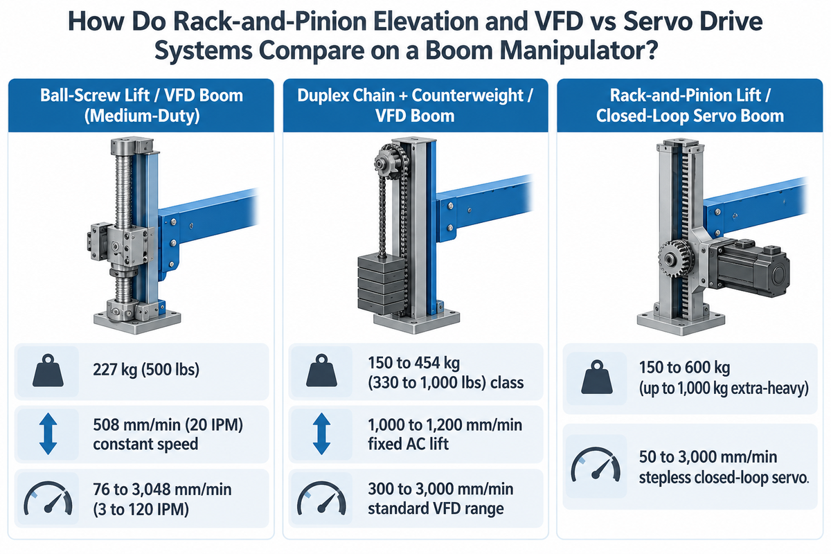
Vertical boom elevating systems use ball-screw drives (508 mm/min lift, 227 kg load), duplex roller chains with counterweights, or milled rack-and-pinion gears (150 to 1,000 kg load). Horizontal crossbeam speed ranges vary by platform. The comparison table lists 76 to 3,048 mm/min for a medium-duty VFD configuration and 50 to 3,000 mm/min for closed-loop servo configuration.
For a boom manipulator, vertical transmission positions the boom at welding height, and the horizontal transmission controls welding movement along the seam. As reported by The Fabricator on the Koike Aronson Cricket-II, medium-duty manipulators use a ball screw for vertical lifting. That ball screw runs at a constant speed of 20 IPM (508 mm/min) and supports a 500 lb (227 kg) load with CAM roller guidance. Standard vessel shop machines use a duplex roller chain paired with an internal column counterweight. Heavy-duty manipulators and Koike Locust series machines use a milled rack-and-pinion elevation drive to eliminate chain stretch over 4,000 to 9,000 mm strokes.
On the horizontal crossbeam, the boom is device driven by a variable speed AC motor or closed-loop servo motor coupled to a rack-and-pinion gear drive. Standard AC VFD inverter drives regulate horizontal travel speed across 76 to 3,048 mm/min (3 to 120 IPM) on the Koike Cricket-II and 300 to 3,000 mm/min (12 to 118 in/min) on AMET XM rack-and-pinion booms. Upgrading to a closed-loop AC servo drive permits control of low speed travel to 50 to 3,000 mm/min for narrow gap TIG and pulsed GMAW welding work.
Smooth boom travel at low speeds (50 to 300 mm/min) depends on the complete drive train rather than the type of motor selected. Backlash in the rack and pinion, the preload of the roller, and the encoder all affect whether stable motion remains. Even high-resolution servo motors produce stick-slip bead ripples if the gearbox has torsional windup or if flux dust binds the CAM rollers. While AWS D16.1M/D16.1 addresses safety for robotic arc-welding cells, evaluating a mechanized boom drive would require assessing mechanical backlash of the drive train and encoder feedback.
| Transmission Parameter | Ball-Screw Lift / VFD Boom (Medium-Duty) | Duplex Chain + Counterweight / VFD Boom | Rack-and-Pinion Lift / Closed-Loop Servo Boom |
|---|---|---|---|
| 1. Representative Industrial Platform | Koike Aronson Cricket-II series | RESIZE LH standard VFD configurations / Standard OEM | AMET XM Servo / Irizar WM / custom servo configurations |
| 2. Rated Boom-Tip Load Capacity | 227 kg (500 lbs) | 150 to 454 kg (330 to 1,000 lbs) class | 150 to 600 kg (up to 1,000 kg extra-heavy) |
| 3. Vertical Elevation Lift Speed | 508 mm/min (20 IPM) constant speed | 1,000 to 1,200 mm/min fixed AC lift | 1,000 mm/min fixed or servo-indexed Z-axis |
| 4. Horizontal Crossbeam Speed Range | 76 to 3,048 mm/min (3 to 120 IPM) | 300 to 3,000 mm/min standard VFD range | 50 to 3,000 mm/min stepless closed-loop servo |
| 5. Minimum Operating Speed Stability | Assess low-speed creep stability at the selected model’s specified minimum operating speed | Rated down to 300 mm/min on standard VFD booms for SAW/MIG | Closed-loop encoder feedback down to 50 mm/min for TIG |
| 6. Vertical Compliance and Lost Motion | Screw and support deflection plus ball-nut clearance | Elastic chain extension plus permanent wear elongation | Tooth, shaft, and support deflection plus gear backlash |
| 7. Vertical Stroke Envelope Limit | Medium-duty compact column envelope | 1,000 to 8,000 mm standard vessel shops | 1,000 to 9,000 mm heavy wind-tower and nuclear |
| 8. Anti-Fall Protection Mechanism | Ball screw can back-drive under gravity; motor brake holds the load while the transmission remains intact | Slack-chain spring pawl arrestor on vertical rack + motor brake | Safety rack pawl arrestor + dual fail-safe motor brakes |
| 9. Primary Welding Process Match | Light SAW, MIG/GMAW, pipe spool cells | Single-wire SAW boilers, tanks, and structural beams | Tandem SAW, narrow-gap cladding, CNC programming |
How Do Cross Slides, SAW Flux Systems, and MIG or Pipe Welding Positioner Cells Integrate?
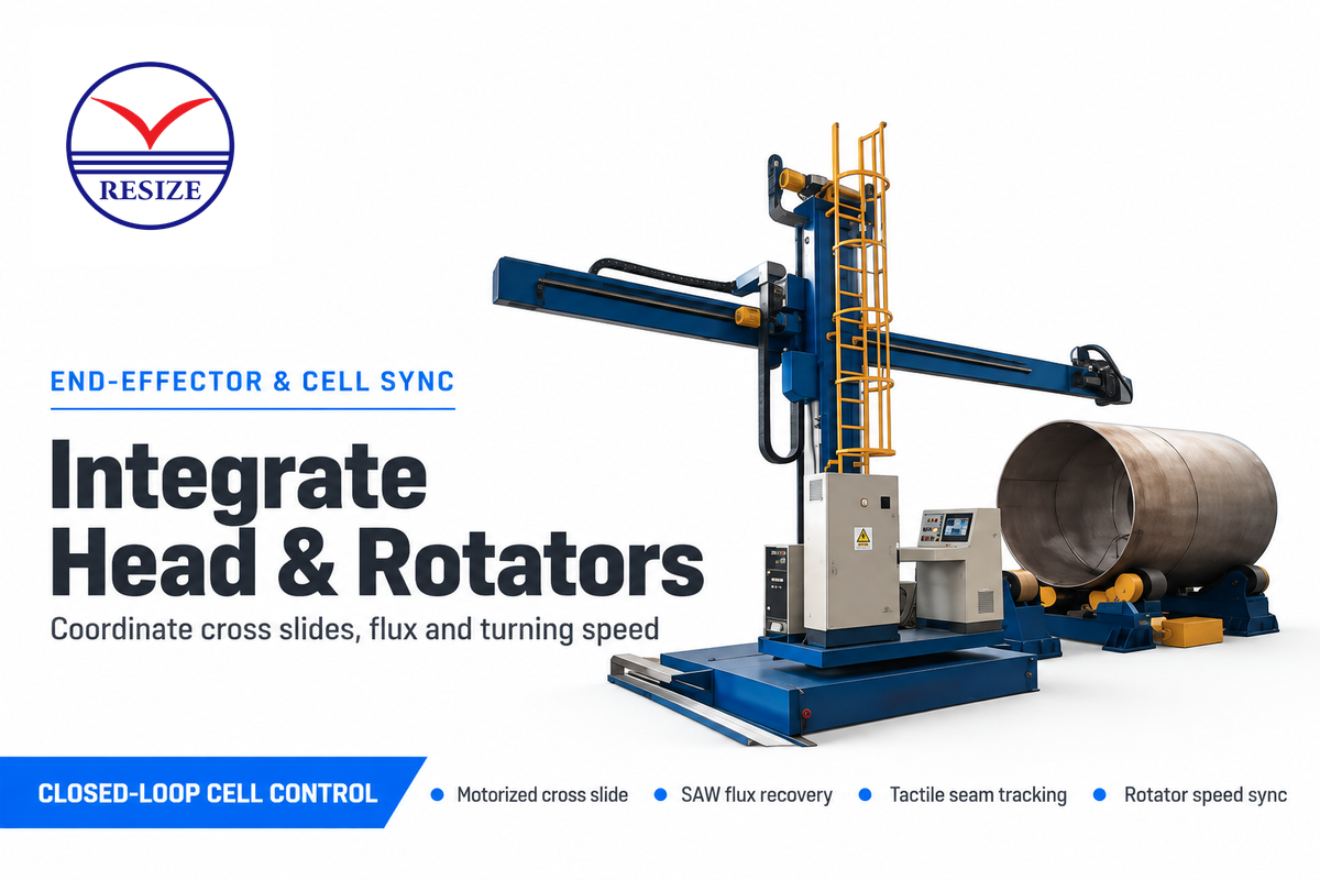
Motorized XY cross slides (100×100 mm or 250×250 mm stroke at 1,000 mm/min) mount directly at the boom tip. Heated 50 to 100 L flux hoppers and 5 HP vacuum recovery units connect to a PLC control system housed in a NEMA Type 12 enclosure. That controller synchronizes seam welding with anti-creep welding rotators (±1.5 mm/rev).
Boom-Tip Carriage, Motorized XY Cross Slides, and Seam Tracking Sensors
The main feature at the forward end of the welding boom is the motorized XY cross slide assembly. Standard AMET and RESIZE cross slides provide 100×100 mm (±50 mm) or 250×250 mm (±125 mm) of fine adjustment at 1,000 mm/min. An operator controls that slide with a 5-way joystick on the hand pendant. A tactile probe or laser seam tracker sensor mounts ahead of the welding torch to guide the cross-slide motors. Meanwhile, an arc-voltage control (AVC) slide holds constant arc length during special welding and advanced welding passes.
Compact boom-tip tooling is required for small shells and pipe spools (see our guide to pipe welding manipulator configurations). Where the internal clearance of a small-diameter pipe isn’t sufficient for a full-size box crossbeam and a top-mounted flux hopper, a narrow reach lance is bolted to the boom flange. They mount the flux hopper at the rear of the boom and use a weld camera to monitor joint alignment and head position during submerged arc welding. During open-arc MIG passes, the camera is used to monitor the weld pool.
Flux Feeding, Vacuum Recovery, and PLC Synchronization with Welding Rotators and Positioners
For high-deposition submerged arc welding, the boom tip carries a 50 to 100 L heated flux hopper paired with a 5 HP vacuum flux recovery separator. The separator is a 5 HP vacuum pump and recycles the flux during the process and filters out slag dust. Power and encoder cables are routed through the boom cable chains to a dust-tight NEMA Type 12 control enclosure. To complete vessel cells, the PLC control system is linked to self-aligning and conventional welding rotators (2.5 to 150 tons). The same PLC cabinet controls industrial welding positioners (250 to 10,000 kg worktables) for chucking.
Integrated Vessel Cell Scenario (Longitudinal vs Circular Seam Switching): In a vessel plant welding 3,000 mm boiler shells, the welder uses a touch-screen pendant to switch between two synchronized modes. For longitudinal seam welding along a 4,000 mm shell course, the PLC locks the turning rolls with brakes. The horizontal crossbeam then travels at 450 mm/min under laser seam tracking. For circular girth welds joining two courses, the PLC parks the crossbeam at a 15 to 45 mm uphill offset ahead of 12 o’clock top dead center. Closed-loop encoders on anti-creep turning rolls then rotate the vessel at constant surface speed and hold axial spiral drift within ±1.5 mm per revolution. Synchronizing the boom axis with closed-loop turning rolls keeps bead geometry uniform and improves arc-on deposition efficiency across multi-pass vessel shells.
Do Welding Manipulator Components Require Dedicated Grounding Brushes to Prevent Slewing Bearing Arc Damage?
The connection used to transport welding current from the workpiece to the power source is separate from the protective frame grounding. Its current and duty-cycle ratings must be sufficient to carry the welding load. For a rotating workpiece, a rotary current collector may be used to bypass the travel and slewing bearings.
Electrical engineering rules separate two circuits on an automated welding cell: protective equipment frame earthing and the high-amperage welding work-lead return path. Under OSHA Technical Manual Section IV Chapter 4, OSHA 29 CFR 1910.254(c)(2), and NFPA 79, the manipulator column and NEMA Type 12 enclosure connect to the shop protective earth conductor. By contrast, the submerged arc welding work-return connection attaches directly to stationary workpieces. On rotating assemblies, it passes through a rotary current collector on the welding positioner fixture worktable sized for the welding load. If return current jumps across the grease film inside the column slewing ring, micro-arcing pits the hardened raceways within weeks.
How Should Buyers Run a Factory Acceptance Test When Auditing a Column Boom Manufacturer?
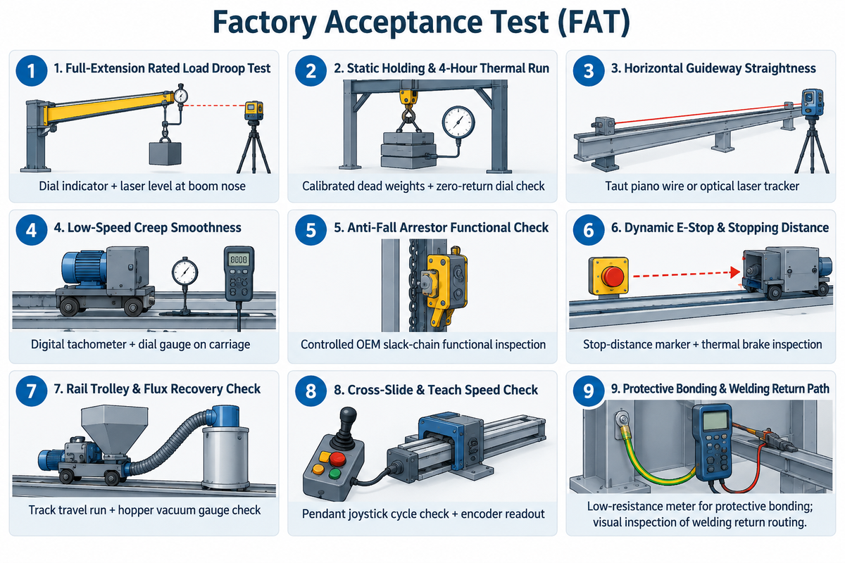
Prior to shipment, customers who send auditors to a column boom manufacturer run a nine-point Factory Acceptance Test (FAT). This involves suspending the rated payload at full reach to measure deflection with a dial indicator. They also measure how straight the horizontal moves using a laser and perform a 4-hour continuous duty cycle. Finally they measure the braking distance and verify protective bonding.
When new machines are purchased or before a retrofit of a used welding manipulator, engineers test the boom under rated full-extension payload. Static boom-tip deflection readings at full reach show cold, downward displacement of dead weight from the unloaded position. These readings are taken at static conditions, and therefore don’t reflect the effects of thermal distortion of the vessel shell during multi-pass submerged arc welding. AWS D1.1/D1.1M:2025-AMD1 addresses structural steel welding and AWS D16.1M/D16.1 addresses Robotic Arc welding and safety. Repeatable manipulator positioning is a separate acceptance criterion for the system.
“Robot speeds during these programming sessions are at a reduced speed, less than 10 inches (250 mm) per second.”
| FAT Inspection Step | Test Setup & Applied Condition | Quantitative Acceptance Threshold | Instrument / Verification Method |
|---|---|---|---|
| 1. Full-Extension Rated Load Droop Test | Suspend rated boom-tip payload at full horizontal reach | Downward tip deflection within OEM spec relative to unloaded datum | Dial indicator + laser level at boom nose |
| 2. Static Holding & 4-Hour Thermal Run | Hold rated boom-tip payload and run 4-hour continuous duty cycle | Zero permanent structural set, brake slip, or gearbox overheating | Calibrated dead weights + zero-return dial check |
| 3. Horizontal Guideway Straightness | Traverse boom across full X-axis under rated head load | Lateral and vertical tracking deviation within OEM straightness spec | Taut piano wire or optical laser tracker |
| 4. Low-Speed Creep Smoothness | Run horizontal boom across low-speed welding range (50 to 300 mm/min) | Continuous stepless travel without stick-slip oscillation | Digital tachometer + dial gauge on carriage |
| 5. Anti-Fall Arrestor Functional Check | Secure saddle with overhead hoist and test slack-chain mechanism per OEM procedure | Spring-loaded pawl engages vertical column safety rack positively | Controlled OEM slack-chain functional inspection |
| 6. Dynamic E-Stop & Stopping Distance | Trigger Emergency Stop during vertical descent and horizontal travel | Immediate motor brake hold and verified stopping distance without chatter | Stop-distance marker + thermal brake inspection |
| 7. Rail Trolley & Flux Recovery Check | Cycle motorized rail travel car, rail clamps, and 5 HP flux recovery unit | Smooth track travel, positive rail lock, and full flux vacuum seal | Track travel run + hopper vacuum gauge check |
| 8. Cross-Slide & Teach Speed Check | Cycle 100×100 or 250×250 mm XY slide and reduced-speed teach mode | Slide speed 1,000 mm/min; robot-integrated cells use reduced-speed teaching below 250 mm/s with enabling controls | Pendant joystick cycle check + encoder readout |
| 9. Protective Bonding & Welding Return Path | Measure frame protective-bonding resistance and inspect the welding return connection | The dedicated welding return connects to the workpiece or rotary current collector, bypassing slewing and travel bearings | Low-resistance meter for protective bonding; visual inspection of welding return routing |
Which Welding Manipulator Manufacturers Supply Heavy-Duty Column and Boom Packages with Travel Cars and Cross Slides?
Heavy-duty columns and booms, supplied by the manufacturer, are integrated with a motorized rail travel car, cross slide, and submerged arc welding. These examples include Irizar (WM Series up to 9 × 6 m), AMET Inc. (XM series, 1 to 4 m strokes, 150 to 600 kg loads) and Koike Aronson (Cricket-II and Locust series). Factory-direct OEM leading manufacturer RESIZE supplies standard LH-3030 to LH-8080 manipulators with rail travel cars and SAW integration.
Engineering buyers match the supplier tier to their vessel shop workflow and control requirements:
- Other platforms discussed include the medium-duty Koike Cricket-II and the Irizar WM 9060 with 9 m vertical and 6 m horizontal stroke.
- RESIZE (Wuxi Yuanpeng Machinery Equipment Factory) manufactures a line of box-section column and boom manipulators for pressure vessel, wind tower, and pipe fabrication. Covering the LH-3030 (3,000×3,000 mm) to LH-8080 (8,000×8,000 mm) models, these configurations are available including base or rail-mounted trolleys, VFD drives, SAW, or 360-degree rotation.
- When you request an engineering quote for custom pricing and lead times, be sure to provide the minimum and maximum shell diameters and the height of the turning roll bed. Also provide your tip payload list for the booms, required speed range for the horizontal, shop voltage (380V/480V, 3 phase), and column splice needs for a 40HQ container.
Frequently Asked Questions
What is the difference between a welding manipulator, a welding positioner, and welding rotators?
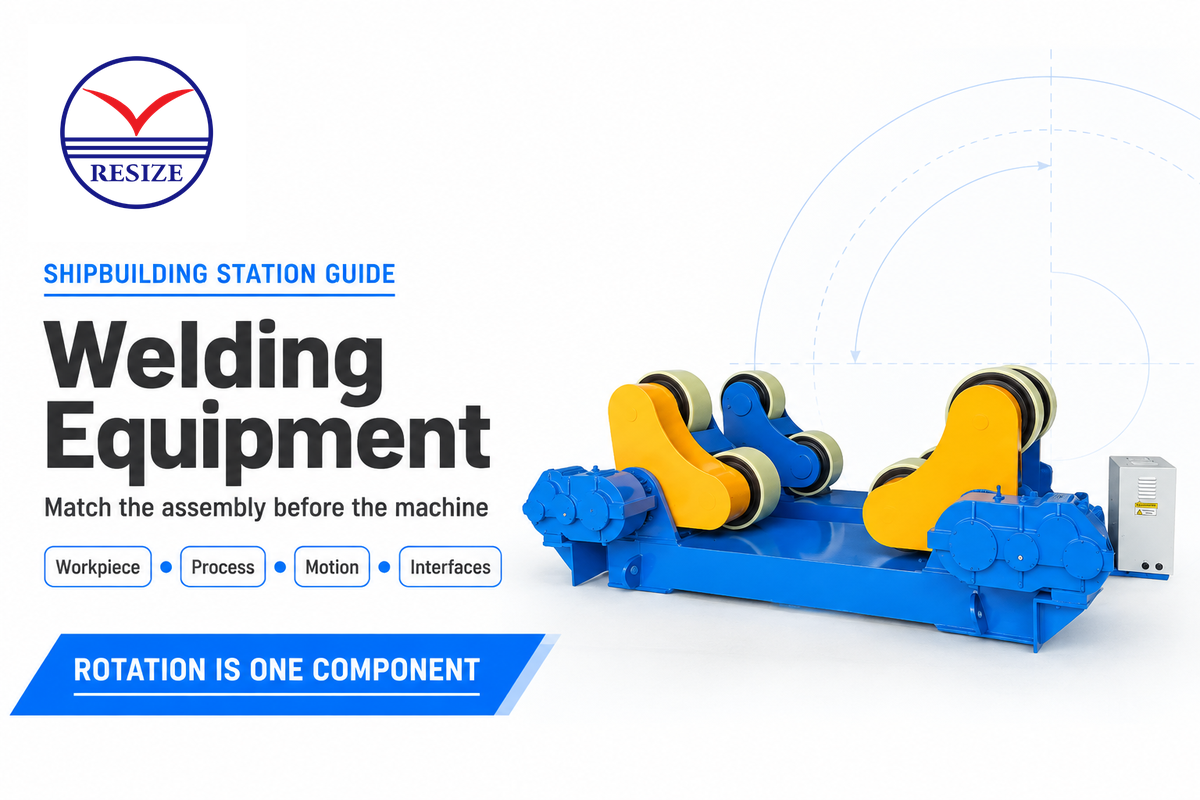
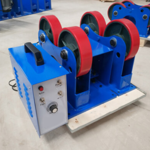
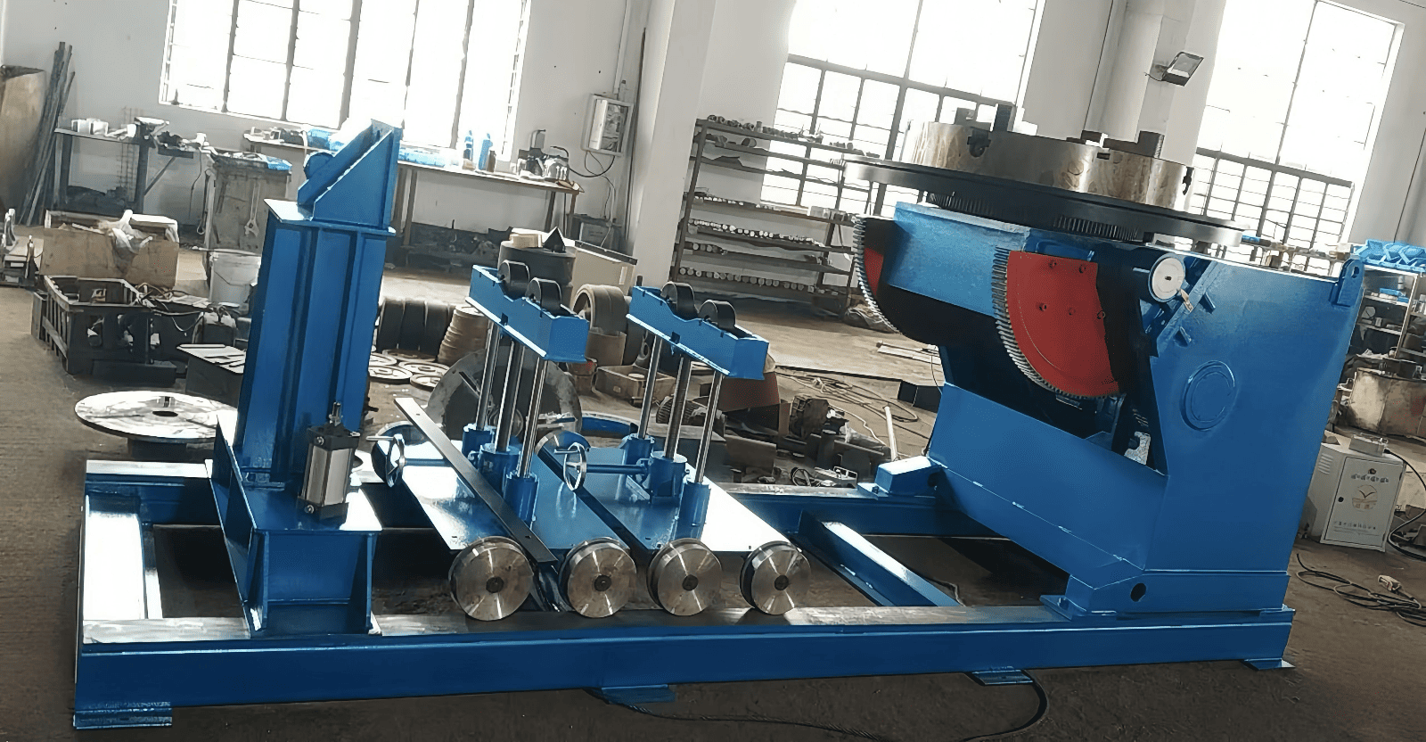
A column and boom welding manipulator vertically moves the welding head horizontally over a stationary or rotating workpiece. A welding positioner tilts and rotates weldments on a worktable. Welding rotators rotate cylindrical workpieces on powered rollers. Positioner worktables have a capacity of 250 to 10,000 kg and place joints into the flat (1G/PA) position. Welding rotators (turning rolls) use a roller bed rated from 2.5 to 150 tons to rotate shells and pipes underneath the manipulator boom.
How much weight can a welding manipulator crossbeam carry at full horizontal extension?
Standard industrial column and boom manipulators carry 150 to 600 kg at the crossbeam tip on AMET XM series frames, or 454 kg (1,000 lbs) on standard medium- to heavy-duty catalog frames. Medium duty, ball-screw booms such as the Koike Cricket-II, carry 227 kg (500 lbs) across multi-process heads. Extra heavy, submerged arc booms, with an operator platform, are rated 1,000 kg and verified by a full extension, static, rated load, holding test.
Why does a column and boom welding manipulator use an internal counterweight inside the column?
Internal mechanical counterweights in the vertical box column balance the dead weight of the saddle carriage, horizontal crossbeam, and boom-tip welding package. It connects through a secondary roller chain and a top sprocket assembly. Counterbalancing the load of the static carriage reduces motor torque demand and jerky movement of the lift. It also minimizes elongation of the roller chain and impact load on the anti-fall mechanism.
How often should welding manipulator guideways, lift chains, and rack gears be lubricated?
Wipe cold-drawn column and crossbeam guideways daily to remove flux dust and apply lithium grease every 40 hours of use. Inspect elevation roller chains and rack-and-pinion teeth weekly. Grease rack-and-pinion teeth every 100 to 150 hours and change worm-gear oil every 2,000 hours.
Can an existing column and boom manipulator be retrofitted with motorized cross slides and seam tracking?
Yes, provided the manipulator’s structural integrity isn’t compromised and its controls and interfaces support the addition, it can accept a 100×100 mm or 250×250 mm motorized XY cross slide and be combined with a laser seam tracker.
What travel speed range is required on the crossbeam and travel car for submerged arc vs MIG welding?
Submerged Arc welding and automated MIG longitudinal seam welding run on stepless horizontal drives from 76 to 3,048 mm/min (3 to 120 IPM) and cover medium-duty Koike Cricket-II booms. Standard AMET XM rack-and-pinion booms run from 300 to 3,000 mm/min (12 to 118 in/min). Applications requiring slow pulsed TIG or narrow-gap cladding use a closed-loop AC servo drive that expands horizontal travel speed to 50 to 3,000 mm/min. Confirm the motorized rail travel car’s positioning speed from its drive specifications. In robot-integrated welding cells, reduced-speed teaching is combined with controls and safeguarding to limit the exposure of the operator to hazardous motion.
Need a Custom Column and Boom Manipulator Sized for Your Vessel Shop?
Send our Engineering Department your minimum and maximum shell diameters, the elevation of your turning roll bed, and the configuration of your submerged arc head. We will calculate net vertical and horizontal stroke clearance, boom-tip payload margin, and foundation anchor specifications for your production line.
References & Sources
- ANSI/AWS Z49.1 Safety in Welding, Cutting, and Allied Processes & AWS A3.0 Standard Welding Terms and Definitions American Welding Society (AWS)
- Patent SE532775C2 / US13/059,778: Welding Crane and Manipulator Assembly for Large Structures ESAB AB / European & USPTO Patent Registry
- OSHA Technical Manual (OTM) Section IV, Chapter 4: Industrial Robots and Automated Welding System Safety U.S. Department of Labor, Occupational Safety and Health Administration
- AWS D1.1/D1.1M:2025-AMD1 Structural Welding Code, Steel American Welding Society (AWS)
- Koike’s Cricket-II Welding Manipulator Supports Multiple Welding Processes The Fabricator (Fabricators & Manufacturers Association, International)
- AWS D16.1M/D16.1 Specification for Robotic Arc Welding Safety & Qualification American Welding Society (AWS)
Related Engineering Guides & Equipment
- RESIZE LH-Series Column and Boom Welding Manipulator Specifications
- Column and Boom Welding Manipulator Sizing Guide: Stroke, Reach & Payload Math
- Pipe Welding Manipulator Configurations for Spool & Vessel Fabrication
- Self-Aligning and Conventional Welding Rotators for Cylindrical Shells
- Industrial Welding Positioners & Rotary Turntables