Welding wind turbines starts with identifying the component. A rolled steel tower shell, a cast blade hub, and a nacelle cover require different decisions on how to join them. For a factory supplying the wind energy industry, that makes a difference on which seams can be automated and which parts will need a separate engineering solution.
Welding wind turbines typically involves steel tower seams and selected fabricated assemblies. Submerged arc welding suits suitable long seams; cast hubs and composite blades require different material and approval decisions.
Quick scope: Steel tubular tower fabrication; component-specific hub and nacelle boundaries; factory process selection. Inputs: drawings, steel grade, thickness, joint position and inspection requirements. No universal welding settings or repair permission are implied.
- A cast hub can’t inherit a steel tower’s welding procedure.
- A faster arc improves output only when the surrounding stations can keep up.
- Procedure qualification and fatigue performance answer different questions.
- Compare production-line quotations against the same part drawings and acceptance requirements.
Which wind turbine components are welded?
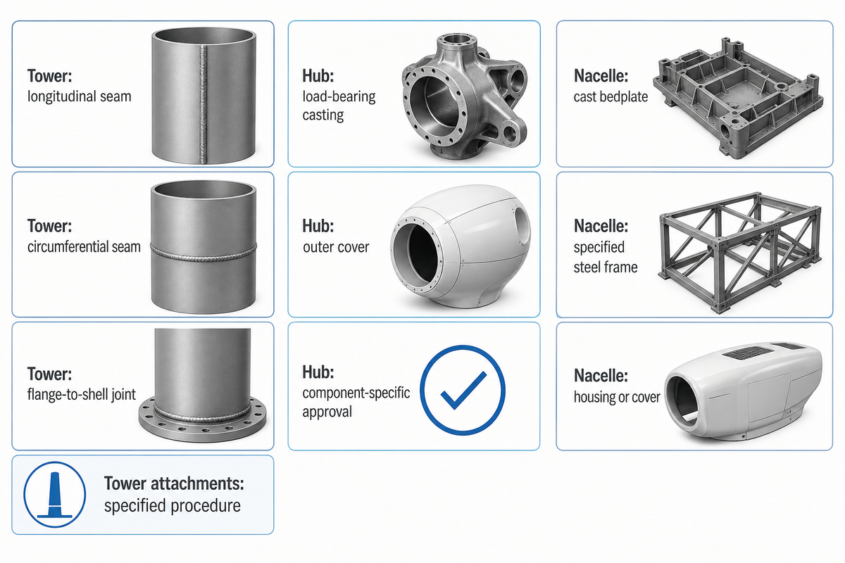
Steel tubular wind turbine towers contain welded seams, but the rotor hub and nacelle combine parts with different materials and functions. Fabricated steel assemblies and castings, as well as composite covers, should be evaluated before a welding process is chosen. The component name doesn’t establish weldability, and it doesn’t authorize a repair.
The 2023 large-castings report by the National Renewable Energy Laboratory identifies hubs and bedplates as major cast-iron components. The DOE separately identifies composite blade and cover materials in wind turbine components. Hence, a hub cover is different from a hub carrying blade loads.
3-Component Welding Boundary Map
| Family and item | Joining decision | Evidence to request | Limitations / Not suitable for |
|---|---|---|---|
| Tower: longitudinal shell seam | Assess mechanized arc welding after rolling | Steel, groove and qualified procedure | Unqualified joint geometry |
| Tower: circumferential shell seam | Assess rotation beneath a welding head | Diameter, support layout and weld access | Unsupported or unstable workpiece |
| Tower: flange-to-shell joint | Review access and distortion control | Joint detail and dimensional acceptance | Assuming the flange remains flat after welding |
| Tower: brackets and attachments | Use the specified local joining procedure | Attachment drawing and load function | Adding unapproved welded attachments |
| Blade hub: load-bearing casting | Identify casting grade and engineering disposition | Material record and component-specific approval | Transferring a tower repair procedure |
| Blade hub: outer cover | Identify composite or other cover construction | Material and joining specification | Treating the cover as structural cast iron |
| Nacelle: cast bedplate | Follow the casting’s engineering requirements | Design and material identity | Assuming every bedplate is a weldment |
| Nacelle: specified steel frame | Assess weld sequence and fixture access | Fabrication drawing and procedure | Applying the route to a different architecture |
| Nacelle: housing or cover | Use its actual material’s joining method | Cover specification | Inferring structural function from appearance |
Use the map for routing: procurement identifies the part, quality checks the material and approval basis, and the plant team decides the station. The map is a synthesis of public sources, not a RESIZE certification or a welding method.
Blades also need a precise distinction. Murray, Roadman and Beach’s 2019 study investigated resistance and induction fusion welding of thermoplastic composite joints. Those coupon-scale results don’t make conventional composite blades steel weldments or prove that every blade factory uses fusion welding.
Wind turbine tower welding: from steel plate to section
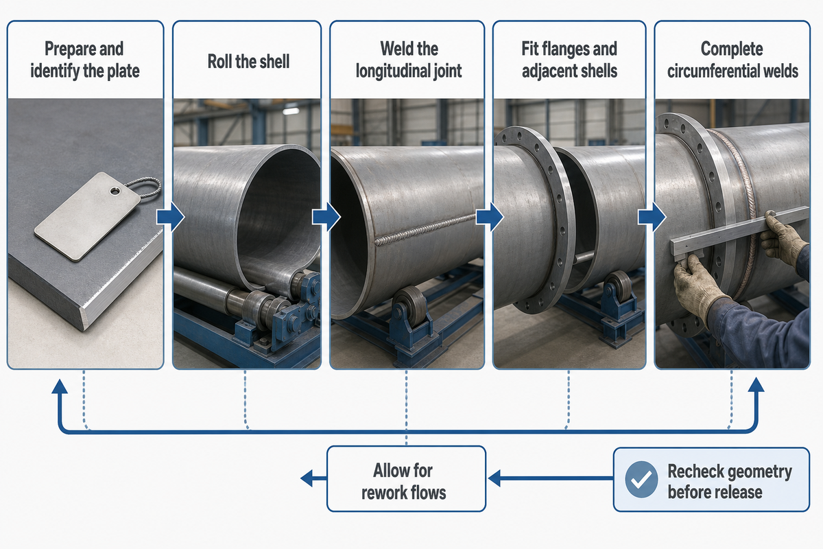
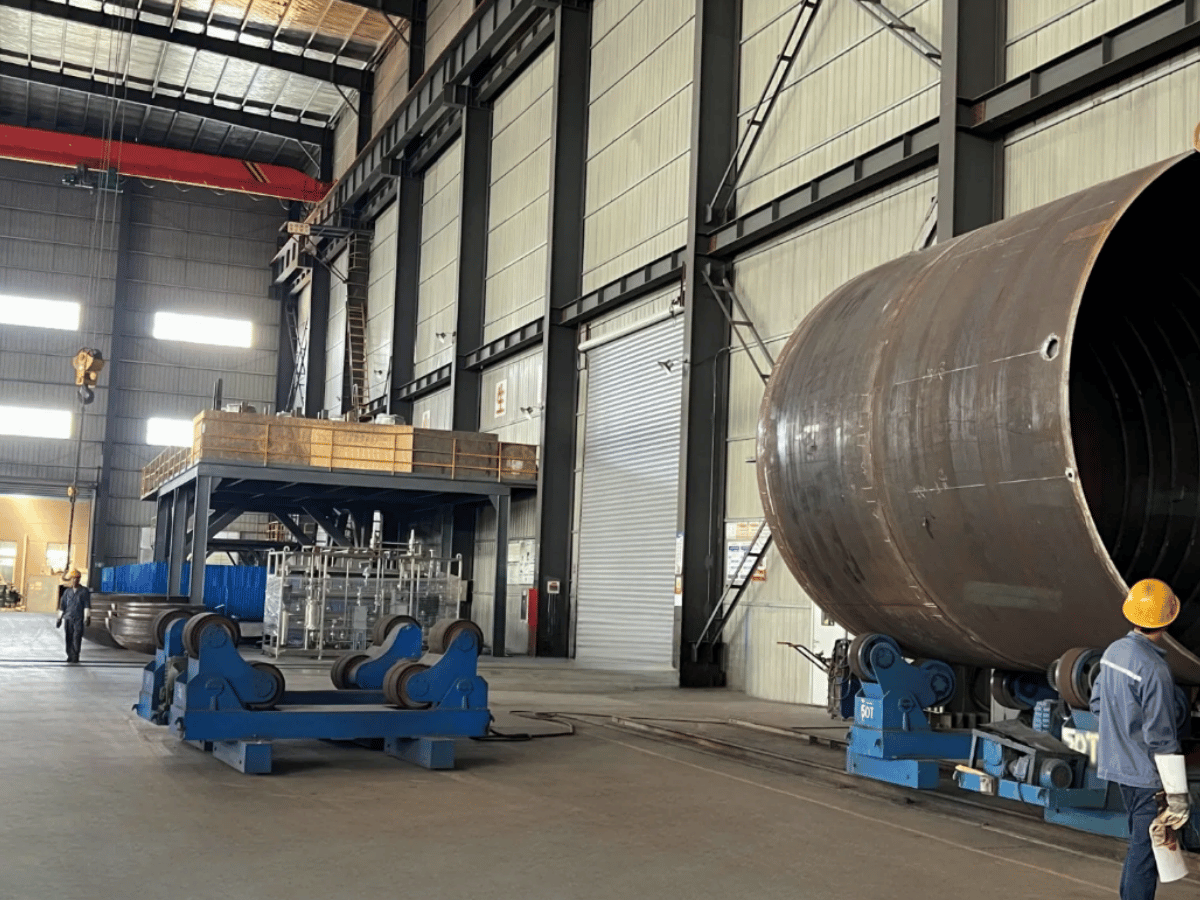
Welding is sequential, and the fit-up and access of weldments matter. A steel wind tower manufacturing process links plate preparation, rolling, longitudinal welding, and assembly of the section, along with circumferential welding. The specified geometry is to be retained at all steps. A welding head can’t compensate for a shell that’s out of drawing limits.
For conventional rolled steel plates, the edge preparation establishes the joint the procedure was qualified to join. Buyers should match plate-edge preparation equipment to the drawing’s bevel, land and preparation tolerances. A brochure’s maximum plate thickness says little about whether the required edge can be produced consistently.
- Prepare and identify the plate. Retain material identity through cutting and edge preparation.
- Roll the shell. Measure the cylindrical or conical geometry before closing the longitudinal seam.
- Weld the longitudinal joint. Provide access for the specified passes, cleaning and examination.
- Fit flanges and adjacent shells. Check alignment before committing the next assembly to production welding.
- Complete circumferential welds. Recheck the geometry and release the section according to the agreed-upon inspection plan.
The stages are consistent with the 2022 Spanish tower-plant case study, though individual factories can, of course, organize their stations differently. The case study describes backwards rework flows when parts can’t pass to the next operation. Allow for those exceptions when comparing layouts.
How Are Wind Tower Flanges Used?
Wind tower flanges enable connections between tower sections in the bolted steel-tower arrangement described in the plant study. The flange-to-shell connection is fabricated in the shop. Section-to-section bolting is a separate operation. Therefore, welding a flange requires control of the joint as well as the completed interface geometry.
Flanges can be assembled before welding, and still require dimensional assessment later. Where turbine tower sections are assembled on-site, a shop-floor mismatch can lead to delivery and erection problems. The approved design determines the connection; not every wind tower uses the same architecture. Therefore, specify acceptable face, bolt-pattern and shell-alignment to the supplier instead of accepting an undefined promise of “high precision.”
Planning scenario: A shop can fabricate the specified shell but doesn’t have access to the inside of the flange joint with the proposed head. Even with increased power source capacity, the welding envelope and inspection access remain unresolved. Address this access in the layout review before ordering the station.
Blade hub materials and repair limits
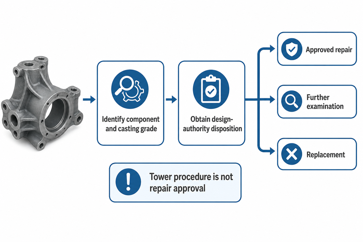
A cast wind turbine hub needs a material-specific evaluation before welding is considered. The casting grade, local condition and the function in the structure govern the evaluation. A repair procedure qualified for a steel tower doesn’t justify that a hub can be repaired or that the repaired casting satisfies the requirements of the design.
TWI’s cast-iron guidance explains why grade matters: welding can create hard, brittle regions and cracking risks around the joint. The guidance discusses cast-iron weldability in general; it doesn’t authorize a particular turbine repair.
Repair-screening scenario: A hub has a crack and a maintenance team asks a tower welder to close it. The first step is to identify the component and obtain the responsible design authority’s disposition. Without that, selection of an electrode to perform the repair would be a reversal of the procedure. The outcome may be an approved repair, further examination or replacement.
Preheat, consumable choice, heat treatment and inspection should occur in accordance with the approved component-specific plan, as applicable. A generic temperature from a cast-iron article can’t account for the hub’s geometry and load history. Separate weld repairs from cosmetic work on an outer cover in the work order, quotation, and completion records.
For new equipment procurement, keep the repair of cast hubs outside the tower fabrication line’s scope, unless the supplier gives a distinct, approved engineering basis. The same large diameter doesn’t make the materials and the failure consequences equivalent.
Nacelle fabrication: frames, interfaces and covers
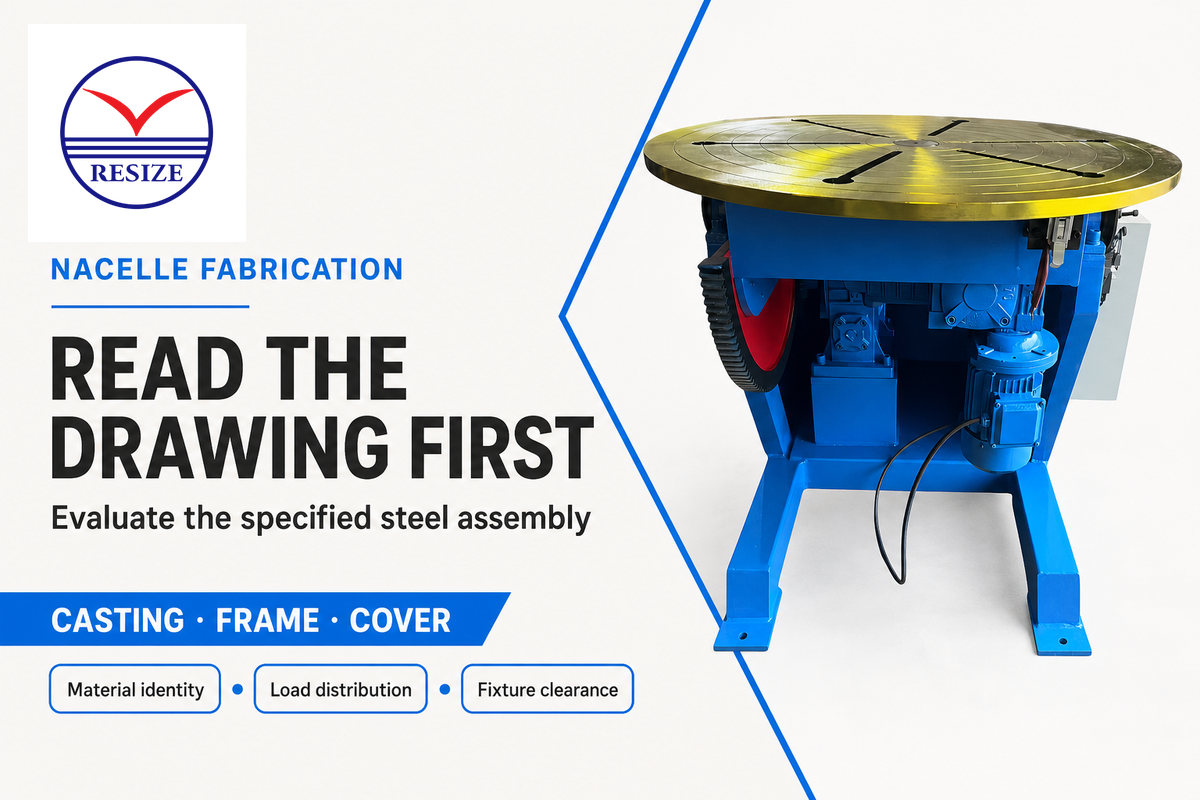
Nacelle fabrication is dependent on the design of the turbine. A nacelle can contain a cast bedplate, specified welded steel assemblies and a separate protective housing. Read the bill of materials and fabrication drawings prior to assigning welding equipment; the nacelle name doesn’t denote a single material or single joining process.
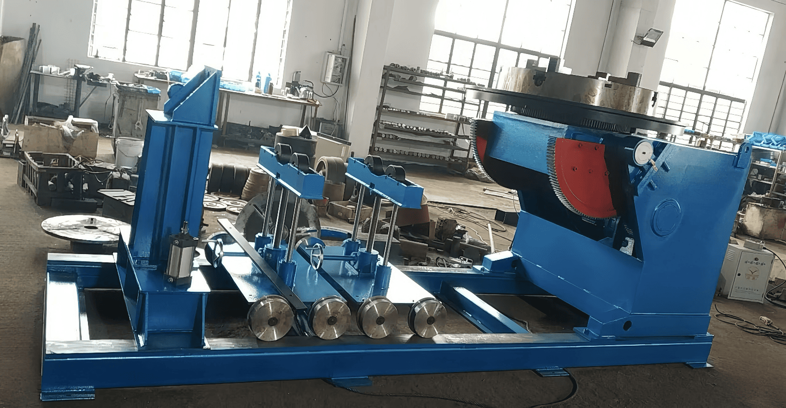
The NREL casting report and DOE material guidance support this distinction between a structural component and its cover. A proposal to automate a fabricated steel frame should identify the actual weldments, their access requirements and the fixture envelope. Welding positioners can be evaluated for the specified assembly; the assessment should include load distribution and clearance, not just the catalogue’s rated mass.
Common Scope Error: Treating a cast bedplate as a steel frame because both support a machine is a scope error. Identifying the part number and material record at the quotation stage is recommended. Separately account for the cover’s joining method and the structural frame’s welding procedure, including when a housing uses aluminium rather than a composite.
Submerged arc welding, GMAW and FCAW: where each fits
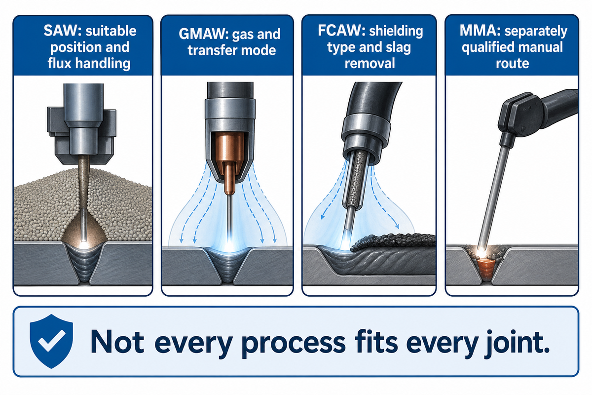
Suitable long tower seams lend themselves to submerged arc welding, while the gas metal arc and flux-cored arc processes offer other combinations of position, access and control of consumables. Selection is joint and qualified procedure driven. Deposition rate isn’t an absolute indicator of weld quality or compatibility with the production layout.
Refer to the TWI submerged arc process guide for information on positional limits of the process. A shell can be rotated to accommodate a joint that’s in the required position for welding with respect to a fixed head. Longitudinal seams require an appropriate head-travel and support arrangement.
| Process | Why consider it? | Check before specifying | Limitations |
|---|---|---|---|
| Submerged arc welding (SAW) | Mechanized joining along accessible, suitable seams | Joint preparation, weld position, flux handling and head travel | Not a general all-position process |
| Gas metal arc welding (GMAW) | Continuously fed wire with adaptable torch access | Shielding gas, transfer mode and qualified position | Gas shielding needs protection from wind |
| Flux-cored arc welding (FCAW) | Wire options for specified positional and mechanical requirements | Gas-shielded or self-shielded wire, procedure and slag removal | Consumables are not interchangeable by process name |
| Manual metal arc (MMA / stick welding) | A separately qualified manual route where specified | Electrode, access and operator qualification | Do not assume suitability for a casting repair |
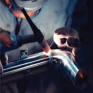
TWI’s guide on GMAW describes the differences between MIG and MAG, and how transfer mode affects operation. “MIG machine” is an incomplete purchase specification. Together with the welding engineer, define the intended steel, gas and qualified operating range.
Flux cored wire also needs a similar definition. TWI’s consumables guide describes wire shielding types and identifies slag removal as a process requirement. A process needs a line with adequate workpiece access for cleaning between passes.
Selection boundary: Do not buy a SAW welding package from a thickness range alone. ISO 9692-2:2024 addresses joint preparation within a defined submerged arc scope. The actual groove, access, material and position still need to match the production procedure; a generic machine capacity is not a qualified joint.
Welding rotators and manipulators: fit-up before arc time
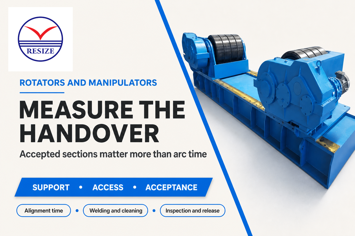
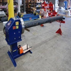
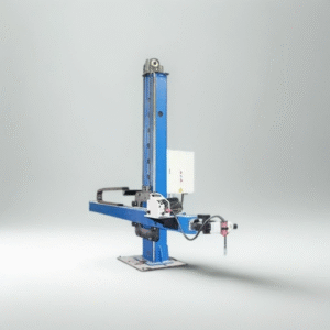
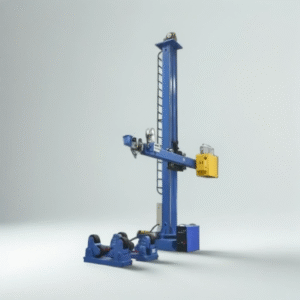
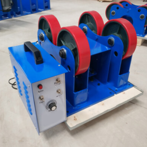
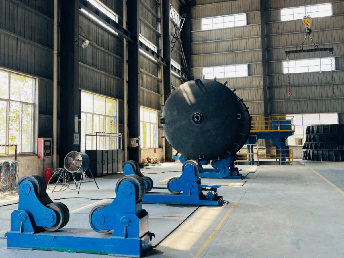
Welding rotators support and turn the workpiece; welding manipulators position or move the head. Their worth is determined by whether the next operation can use the part as received. Measure each handover to decide if more welding automation will increase the output of the finished section.
Lorenzo-Espejo and others looked at nearly 900 sections and more than 7,400 ferrules from the March 2018-February 2021 records of a Spanish factory. For them, bending was the production bottleneck. Minor ovality and flatness problems also affected fitting. The opposite is the case for TWI’s HiWeld project, where welding time and cost of thick offshore sections are the constraints.
| Station or handover | Possible constraint | Record and responsible buyer | Limitations / Not suitable for |
|---|---|---|---|
| Plate preparation | Edge rework delays rolling | Preparation time and rejected edges; plant / QA | Inferring groove quality from cutting speed |
| Rolling | Shape prevents the next fit-up | Geometry and rework time; plant / QA | Using one plant’s bottleneck as a universal rule |
| Longitudinal fit-up | Gap correction occupies the welding station | Alignment time and approved limits; plant | Using a bigger arc to correct poor fit-up |
| Longitudinal welding | Pass time limits release | Arc, cleaning and interruption time; welding engineer | Comparing deposition alone |
| Flange fitting | Handling and alignment consume the shift | Moves and fitting time; plant / procurement | Assuming a faster weld removes crane waiting |
| Shell-to-shell assembly | Geometry mismatch sends parts backward | Fit-up rejection and return path; QA | Counting unfinished assemblies as output |
| Circumferential welding | Rotation or access interrupts the seam | Travel stability and accessible envelope; plant | Assuming rated load proves stable operation |
| Inspection and repair | Release queue holds finished welds | First-pass acceptance and repair hours; QA / finance | Treating welded sections as accepted sections |
| Coating and dispatch | Downstream capacity delays shipment | Accepted-section release times; plant / finance | Claiming shipment gains from arc speed alone |
For equipment detail, use the existing wind turbine welding rotator guide. Compare fit-up rotators against alignment needs and welding manipulators against reach and head travel. A column and boom arrangement must be assessed over the required working envelope of the large steel assembly.
How Can Welding Automation Improve Wind Tower Production?
Automated welding can improve wind tower production by easing a measured constraint and holding the necessary process conditions. The best comparison is the accepted sections through the entire route. A station trial should include loading and aligning, welding, cleaning and inspection, and handover to the next operator, so that saved arc time isn’t mistaken for saved shift time.
Have both plant and finance teams review the same trial record. Plant needs to establish a practical movement sequence; finance needs reliable capacity and labor assumptions. A rejection based on quality should be in that record, even if the arc ran continuously. The resulting quote should show the welding package, and distinguish the handling and/or inspection investment needed to reach the targeted output.
When not to buy a faster welding station
If a shell spends the shift waiting for alignment or bending corrections, determine first why the current route can’t feed the weld station. The Spanish plant case study shows a documented example of both geometry and reversed flow. Buying a higher-capacity power source before correcting that handover may result in the same situation.
A separate problem is accepting only the preweld shape. Lin and colleagues’ 2023 tube experiments measured weld depressions before and after circumferential welding. Such imperfections matter when assessing how thin-walled structures buckle. The approximately quarter-scale specimens don’t provide production tolerances, but the findings support including postweld geometry in a representative trial.
Consider an expansion where the welder is idle while the crane moves assemblies. Time that waiting and check the proposed transfer arrangement before adding another welding head. If measured arc time dominates a thick-section route, then evaluate process changes with the welding engineer. The decision turns on the observed constraint and accepted-part output, not a preference for more automation.
Steel grade, welding consumables and inspection
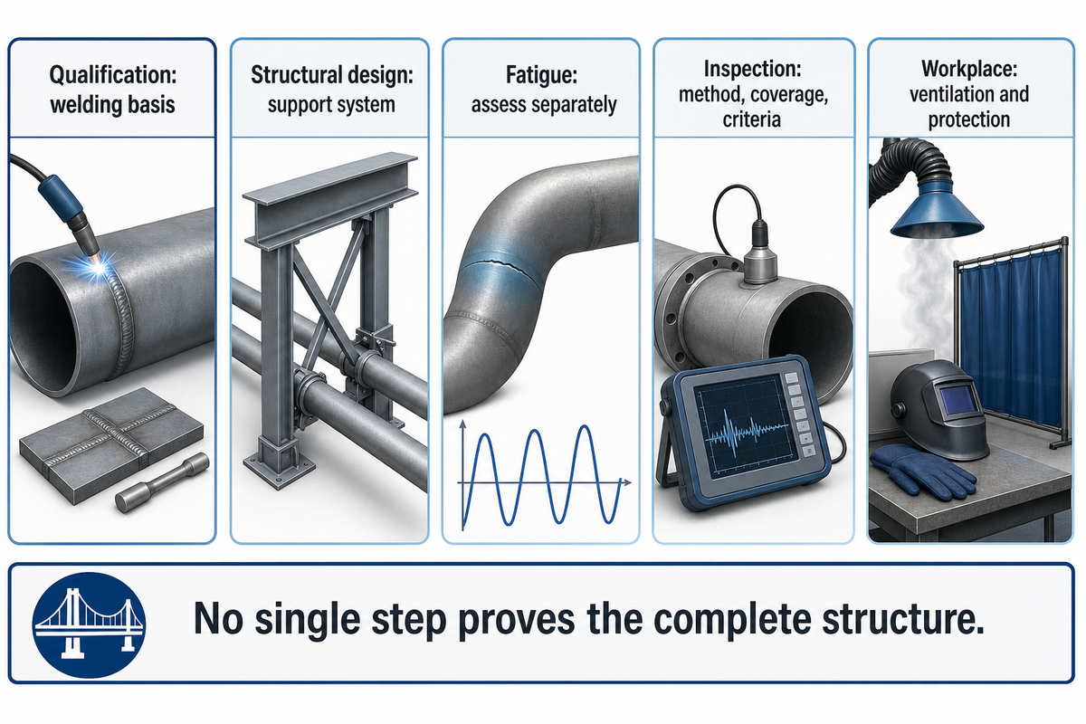
The various types of steel, the welding consumables and inspection must work as one specified production system. The material and joint determine the process, and qualification defines a basis for welding. Inspection verifies the required characteristics. None of those steps alone proves that the complete turbine support structure meets its fatigue and structural requirements.
The AWS D1.1/D1.1M:2025-AMD1 overview addresses structural steel welding qualification, fabrication and inspection. The contract should name the code and edition in question. For onshore wind support structures, the published scope of IEC 61400-6:2020+AMD1:2025 addresses structural integrity at the support system level. These documents answer different questions.
Fatigue should be assessed separately. In their March 2024 fatigue testing explanation TWI describes the distinction between bend, Charpy and tensile tests, and information on fatigue performance.
“Specific fatigue tests are needed for that.”
Cao and colleagues’ 2026 study examined 25 mm Q420 welded specimens and the effect of surface condition on fatigue. That specimen result doesn’t qualify an entire tower. Ask the responsible engineer how the selected joint detail, finish and acceptance plan connect to the design’s fatigue assessment.
Set inspection access while designing the station. ISO 17637:2016 covers visual testing of fusion welds and permits its application to joints before welding. The project still defines the examination methods, coverage and acceptance criteria. NDT records cannot correct a missing material identity or an unapproved procedure.
Plan the handover to corrosion protection as well. DNV-RP-0416 addresses wind support structures within its published scope; it excludes rotor and nacelle design. Keep coating preparation and release responsibilities visible without presenting that document as a universal nacelle specification.
Shop-floor boundary: Enclose or ventilate the work as required by the actual operation, and plan fire prevention and personnel protection. OSHA’s welding and cutting requirements address these controls. A flux-covered arc doesn’t remove the need to assess the workplace hazards.
Specifying a wind tower production line
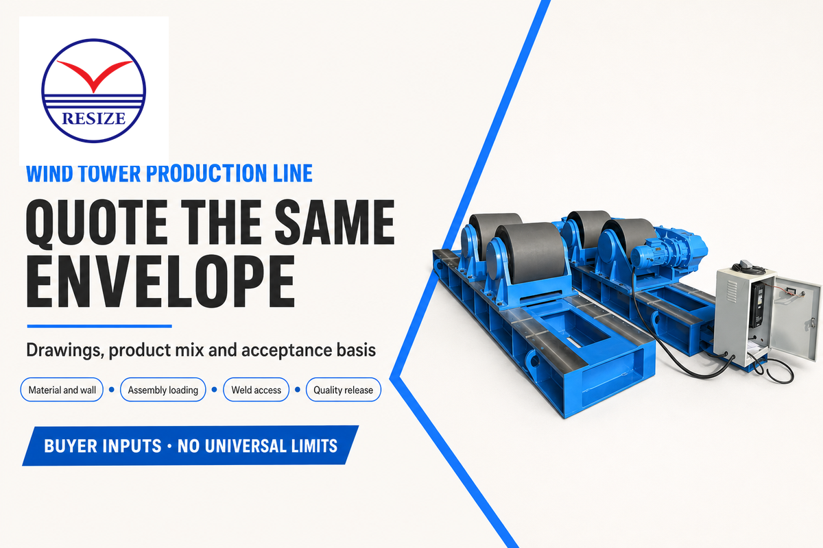
A quotation for a wind tower production line is useful, when all competitors price the same product range and process route, and acceptance basis. Representative drawings and the anticipated product mix are a good starting point. Separate the welding package from handling, preparation and downstream release, to ensure the scope of purchase is aligned with the factory’s measured constraint.
Your relevant starting point is RESIZE’s wind tower production line. Send the supplier the inputs below along with the drawings. Request a station-by-station proposal, and identify which of these items require a representative trial before a capacity claim will be considered in the business case.
RFQ checklist: define the drawing envelope before comparing prices
| Parameter | Recommended range | Why it matters | How to verify |
|---|---|---|---|
| Shell dimensions | Drawing minimum and maximum diameter / length, mm | Sets support spacing, travel and access | Layout overlaid with representative drawings |
| Material and wall | Actual steel grades and thickness range, mm | Defines the procedure and preparation scope | Material specification and joint schedule |
| Assembly loading | Part mass, kg, and load distribution by configuration | Rated mass alone does not describe the supported part | Supplier’s load and support assessment |
| Weld access | Required internal / external reach, mm | Prevents inaccessible seams and cleaning areas | Head-envelope review with the proposed fixture |
| Product mix | Planned sections per shift by drawing family | Exposes changeovers and mixed-route constraints | Timed representative trial with interruptions recorded |
| Quality release | Project-specified geometry and examination limits | Defines accepted output | Agreed inspection and acceptance plan |
| Plant interfaces | Available floor envelope, utilities and handling capacity | Separates machine purchase from installation work | Joint layout and utility schedule review |
The ranges are buyer supplied inputs, not recommended engineering limits. A heavy-duty label can’t replace them. The procurement team can assess inclusions, the quality team can approve release evidence, and the finance team can review manufacturing costs, to include rework and installation. A cost-effective proposal must address these costs. No public source establishes a reliable turnkey wind tower cost for every factory.
For a capacity expansion, bring the station timing record. For a new product family, include the most stringent access and geometry cases. If a proposal was adapted from pressure vessels, replace their assumed materials and inspection with your tower specification. These starting points can lead to different welding solutions even if the desired annual output is the same.
What is changing in wind turbine manufacturing?
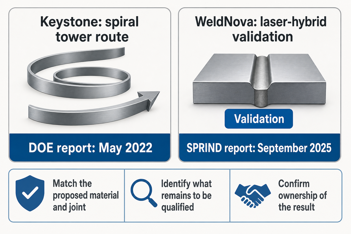
Wind turbine manufacturing developments should change an equipment decision only when their demonstrated scope matches the buyer’s parts. Spiral tower production and alternative thick-section welding methods address specific manufacturing requirements. Their project dates, owners and qualification status are more important than a general statement that the wind industry needs welding.
DOE’s May 2022 account of Keystone’s spiral-welding development describes a different tower-manufacturing route. It’s a dated project example, not evidence that all current wind farms use spiral-welded towers or that RESIZE owns that technology.
In September 2025, SPRIND reported WeldNova validation work on magnetically supported laser-hybrid welding of 30 mm seams, including mechanical and fatigue qualification work. SPRIND is involved in the development’s funding context. Treat the report as project evidence rather than an independent guarantee of production savings.
A procurement comparison requires the proposed joint, test evidence and production boundary for each alternative. A demonstration on a plate coupon doesn’t establish the acceptance of a completed tower. A process that reduces arc time still requires a handling route, access for inspection, and a qualified operator or control system.
Wind power investment provides the business context, but renewable energy production targets don’t define welding automation equipment. Turbine construction at greater heights, offshore wind designs and the supply chain can create different fabrication requirements; use the actual project drawings to establish them. HiWeld’s thick-section work includes monopiles. It shouldn’t be assumed that a tower shell manufacturing route is the same as HiWeld’s route for monopiles. Separate research-stage alternatives from offered equipment with a defined production acceptance trial.
Date evidence provided in the proposal for a 2026 procurement review. Older work may be described in an archived page, and a patent describes an invention regardless of deployment. What has been demonstrated on the proposed material and joint? What remains to be qualified? Which organization owns the result? Compare the answer to the conventional route before assigning a value to a welding technology.
Frequently asked questions
What kind of welding does the wind industry use?
Wind turbine fabrication uses different processes for different joints.
Submerged arc welding is a candidate for a suitable long steel tower seam. Other qualified processes may include gas metal arc and flux-cored arc processes. The route is determined by the material, access and position. A process used on a tower can’t automatically be used on a cast hub or composite blade even if the same factory performs all the work.
What Are the Manufacturing Requirements of a Wind Tower?
The turbine design and project contract define the manufacturing requirements.
The specification should incorporate material identity, dimensional acceptance, qualified welding procedures, personnel and inspection records. Identify the applicable code and edition before ordering production equipment. Require the supplier to justify each step in the acceptance plan. A catalog capacity figure doesn’t establish those requirements or qualify the finished structure for its intended service.
Can a cast wind turbine hub be repaired by welding?
A cast hub requires a component-specific engineering disposition before repair welding.
Establish component and casting grade and damage identification and obtain the responsible design authority’s decision. For permitted welding, the repair requires an approved procedure and examination plan for the component. A tower welding procedure can’t be assumed to be valid for the repair. The decision may warrant further assessment or a different repair route, including repair by replacement.
What’s NDT testing?
NDT means nondestructive testing of a component.
The project defines the type of examinations to be conducted, the extent of coverage, and acceptance criteria. A given examination method doesn’t reveal all defects, and an inspection doesn’t replace a qualified manufacturing procedure.
What is a Wind Turbine Tower?
The tower supports the turbine above its foundation.
Steel tubular, concrete and hybrid structures are available. Here, the discussion centers on welding and the production-line of fabricated steel sections; the approved design governs the connections.
Are wind turbine blades welded?
Blade joining depends on the composite system and design.
Steel tower welding and blade construction differ. Thermoplastic composite fusion welding has been studied at a coupon level. That work doesn’t establish a uniform commercial practice for blade construction.
Prepare a production-line enquiry: Send RESIZE your tower-section drawings, material range, product mix and current station constraints. Request a proposal tied to accepted output, with the trial conditions and excluded work stated.
Technical scope: This guide uses public institutional guidance, standard scopes and attributed research. Comparison maps are primarily to aid procurement decisions. Project drawings, responsible engineering approvals and sign-off determine fabrication and repair actions. No private RESIZE tests, or unverified certifications are stated.
References & Sources
- National Renewable Energy Laboratory, Large Castings for Wind Turbines (2023), via OSTI
- U.S. Department of Energy, Wind Turbine Recycling
- Murray, Roadman and Beach, thermoplastic blade-joint welding study, Renewable Energy 140 (2019), 501–512
- Lorenzo-Espejo et al., Machine Learning-Based Analysis of a Wind Turbine Manufacturing Operation, Sustainability 14 (2022), 7779
- TWI, Weldability of Materials: Cast Irons
- TWI, Submerged Arc Welding Process
- TWI, What Is Gas Metal Arc Welding?
- TWI, Welding Consumables, Part 4
- International Organization for Standardization, ISO 9692-2:2024 public scope
- TWI, HiWeld project summary
- Lin et al., Measurement of Weld Depressions in Thin-Walled Steel Tubes Before and After Circumferential Welding, SSRC (2023)
- American Welding Society, D1.1/D1.1M:2025-AMD1 overview
- International Electrotechnical Commission, IEC 61400-6:2020+AMD1:2025 public scope
- TWI, Fatigue Testing Maximises Safe Life of Critical Joints (2024)
- Cao et al., Q420 welded-joint fatigue study, Metals 16 (2026), 148
- International Organization for Standardization, ISO 17637:2016 public scope
- DNV, DNV-RP-0416 public scope, edition 2016-03, amended 2021-10
- Occupational Safety and Health Administration, 29 CFR 1910.252
- U.S. Department of Energy, How Spiral Welding Is Revolutionizing Wind Turbine Manufacturing (2022)
- SPRIND, WeldNova development report (September 2025)