
To ensure high levels of precision and accuracy in any manufacturing or building task, welding blueprints should be used fulfil that role. In all these additional notations and symbols that make such blueprints, the seam weld symbol usually comes in as a standard and one that is specifically useful to welders so they can produce efficient joints. So what exactly is the meaning of this particular symbol? Why is it necessary for a welder to understand it? In this piece, the relevance of the seam weld symbol is discussed while outlining its features and how each of them is used in practice. It does not matter if you are a professional welder wanting to refresh forgotten knowledge or someone who is just entering the field and would like to learn how to read blueprints, this book is meant for you, because no one’s ability to perform well stays the same without understanding how things work.
The Basics of Weld Symbols
In the land of welding, a seam weld symbol is an essential element of design drawings, specifying the type and position of a seam weld needed. These symbols offer effective communication between the designer, drafter, welder and all other stakeholders involved in the project. This is explained by the fact that the basic elements of a seam weld symbol are the reference line, the arrow line, and the weld symbol proper: it is the weld symbol that indicates the welding process to be applied. Ring these symbols if compounded welders know how to do their job in accordance with the initial plan and as a result, the project is produced without diminishing the strength and effectiveness of the structure.
Definition of Weld Symbols
Technical drawings employ standardized notations called weld symbols to detail the types, sizes, and locations of welds. In latest industry standards, it is mentioned that these symbols are a common platform of communication when it comes to welding design and fabrication. This is important because it eliminates any doubts about the designs, allowing everyone involved in the project, from engineers to welders, to read the drawing without misinterpretation. The basic weld symbols incorporate information such as the type of joint (such as a butt joint, a fillet, or a lap joint), the size of the weld, and any other information such as the finishing process and the particular welding sequence, if necessary. Manufacturers and others involved in fabrication can comply with safety, quality and law by simply following these rules and symbols.
Importance of Weld Symbols in Fabrication
It is often essential to incorporate weld symbols in the engineering process because it might assist in improving accuracy, competence and quality. Because these symbols can be read and interpreted to understand the type of seam weld, its dimensions, exact position and some additional requirements, they prevent any chances of misunderstanding. This achieves optimal production, helping to minimize the inaccuracies that occur. Also, the use of seam weld symbol safety conforms to the norms’ standards, thus increasing the effectiveness of a manufacturing process.
Types of Weld Symbols
There are various types of weld symbols including groove, fillet, square, corner-flange, edge, plug/slot, and surfacing welds, designated to convey specific weld requirements.
| Weld Type | Use Case | Position | Key Traits |
|---|---|---|---|
| Groove | Deep joining | Along edges | Strong bond |
| Fillet | Corner joints | 90° angles | Triangular form |
| Square | Flush edges | Flat surface | Simple prep |
| Corner-Flange | Angular parts | L shape | Reinforces joint |
| Edge | Thin materials | Sheet edges | Seam strength |
| Plug/Slot | Overlapping | Holes/slots | Fills gaps |
| Surfacing | Surface build | Exterior | Layers added |
Seam Weld Symbols Explained

Seam weld symbols are a set of symbols used in welding engineering to specify what kind of welding is required on the particular part of the structure. Each seam weld symbol represents a particular welding procedure with all details attached described in the table above. These symbols explain such complex welding instructions in a simple format that can be easily understood by engineers, welders and the inspectors. For instance, groove welds provide bonding, especially along the edges, while fillet welds create strong corner joints that add strength to the construction. The proper use of these symbols helps in applying the correct type of weld that the material and the manufacturer’s design requires for complex structures and ensures that the structures remain viable and strong in various environments.
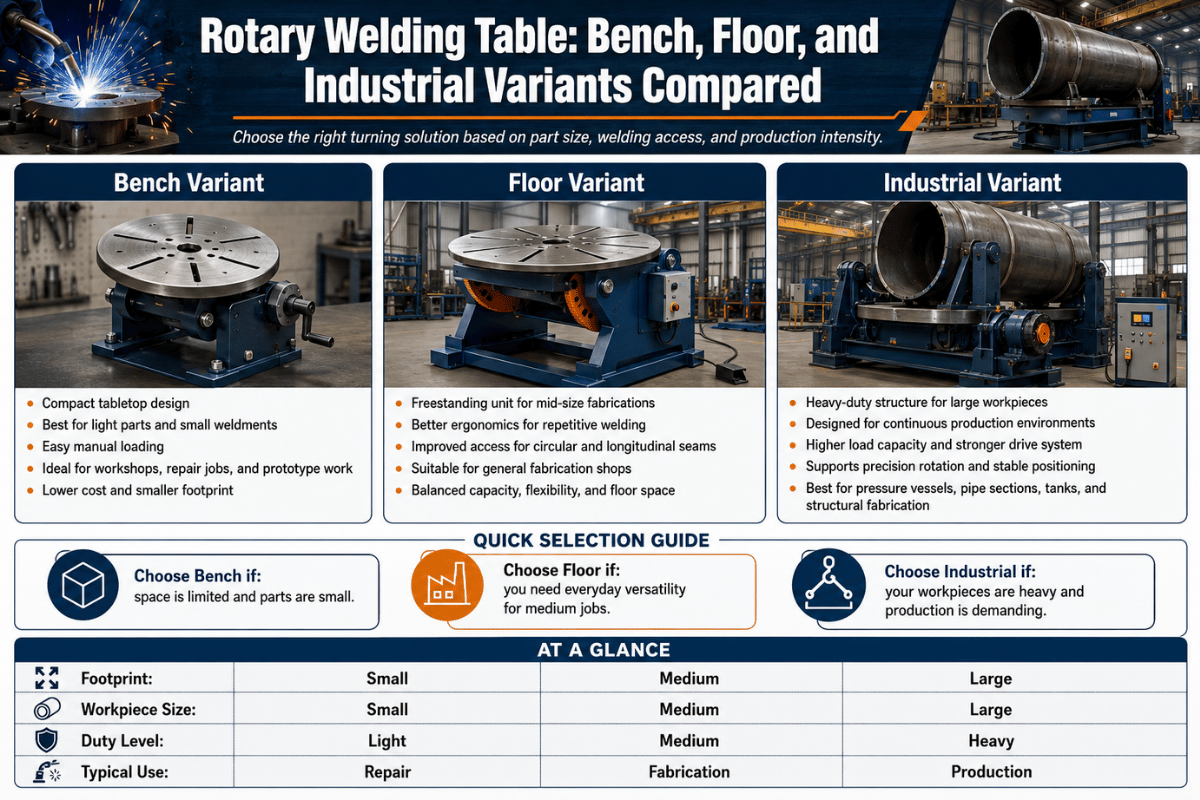
What is a Seam Weld?
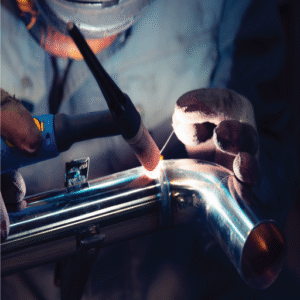
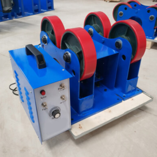
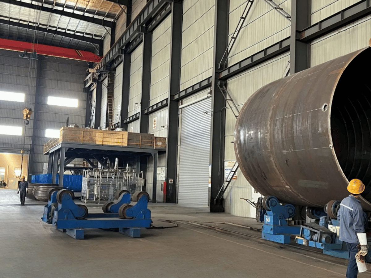
Continuous, lengthy sections of sheet metal can be joined using a seam weld. This is usually accomplished through methods known as heat resistance welding, where the heat produced is mounted over an exerted pressure to bond the two components. Seam welding also consists, in most cases, of rotating the electrodes with wheels – this enables strict adherence to creating the seam, ensuring consistency.
Welding with a seam is generally used in industries such as vehicle construction, engineering, and manufacturing. This includes items like tanks, exhausts, and pipes, where welding is needed in the form of a seam or weld. The process can complete the long weld with uniformity and less material deformation, making it reliable and cost-effective in large volumes.
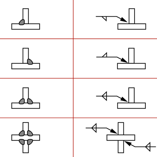
Structure of a Seam Weld Symbol
A seam weld symbol helps show in diagrams the location and type of seam weld needed. Usually, a seam weld symbol consists of the following elements:
- Reference Line: It is the horizontal line at the bottom of the sinking, against which the placement of other elements takes place.
- Arrow: It assists in pointing the exact position of the weld on the drawing from the reference line.
- Tail (Optional): One may decide to add welding methods or any other specifications in case any.
- Weld Symbol: This type (e.g. straight/slanting/curvy bar) can be used to show the seam weld
- Dimensions and Specifications: These can also be attributes of the weld, such as its shape or length.
These components are all crucial in maintaining accuracy of the idea being communicated. Standard concepts like those that have been Imposed by the American Welding Society (AWS) are all present in this v.
Common Variations of Seam Weld Symbols
Therefore, there are several basic variants of a seam weld symbol in a welding plan:
- Square Groove Seam: This design is masked by a straight line, indicating a square groove that requires no edge preparation beyond the joining.
- V-Groove Seam: Shown with an open letter V pattern, this indicates a weld in which both edges need to be processed to create a V-shaped groove.
- Lap Joint Seam: What are parallel lines? This replaces the need to explain the overlapping surfaces joined at the seam.
- Fillet Seam: Candidates state a consists of a triangle in reference to the process of making joints to form an angle of 90 degrees using a fillet weld.
- Spot or Plug Seam: Has a circle in the symbol, which involves spot welding in several parts of the seam or a plug placed in a part of it.
The secondary purpose of these changes is to assist in the correct interpretation of how to undertake the project, economic consistency, & quality assurance of both the production and the assembly operations.
Spot Welds and Their Symbols
Welds used in design drawings have a seam weld symbol circle to show spots where circular localized welds are to be used mainly for joining overlapping (extending segments with) non-metallic materials such as sheets. Symbols such as these clearly define the position of the weld and any required processes to avoid interactions during production or construction.
Understanding Spot Welds
Spot welding is a technique used for joining several sheets of thin metals by producing heat at spot points in which pressure is applied. It requires clamping the materials using electrodes and applying an electric current to heat the metals being joined, causing them to melt and form a cohesive joint. Many industries, especially automotive, make use of spot welds due to their effectiveness, robustness, and adherence to mass production techniques. This is especially important when other methods, like seam weld symbol, are not appropriate.
Spot Weld Symbol: Interpretation and Use
The seam weld symbol serves as a pictorial representation on the mechanical schematics typical in welding processes as it is intended to show how individual welds should be placed on the surface of the material. It is a shape, very much like a simple cylinder, that appears with the main weld lines of the symbol. Sometimes, for example, in the case of the standards provided for by ISO 2553 and AWS A2.4, some dimensions, such as the number of parts or the distances between them or welds, may be positioned either within the vehicle, above it, or below it. These symbols assist engineers and welders in placing the weld according to design requirements, including structural integrity, and in properly locating the weld area.
Resistance Spot Welding Techniques
Resistance spot welding is a highly efficient process in which two or more metal sheets are joined together by pressure and heat generated by an electric current. Electrodes are placed on either side of the workpieces so that a current passes through the contact point, causing localized melting and fusion. Due to its speed, automation possibilities, and the creation of strong, reliable joints without the need for filler materials, RSW finds vast application in sectors, especially in automobile manufacturing. Electrode pressure, welding current, and weld time are chief factors affecting spot weld quality. All variables should be controlled well to make good spot welds.
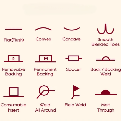
Supplementary Symbols in Welding
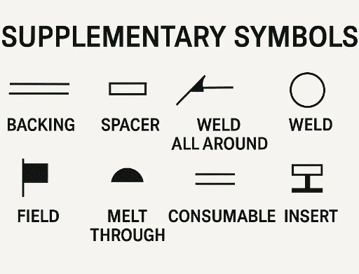
These symbols are called supplementary welding symbols because they provide additional information about the weld on a welding diagram. These symbols supplement the basic weld symbols and indicate specific requirements such as weld contour, finish, or other work that must be done on the weld. Some examples include symbols for flush, convex, or concave contours, as well as notes related to grinding or machining. These symbols make sure that the welds are correctly specified and improve the interface between the designer and the welder.
Overview of Supplementary Symbols
Supplementary symbols give additional details about the weld profile and processing. These contour symbols, for example, flush, convex, and concave, describe the weld surface shape being accepted. The finish symbols outline the approach to be utilized for obtaining the contour, such as grinding, machining, and chipping. These symbols must be applied together with the weld symbols to fully communicate all requirements, ensuring the weld satisfies design and quality criteria. The use of such symbols ensures that the communication is standardized, reducing misinterpretations and making welding projects more efficient.
How Supplementary Symbols Enhance Clarity
The supplementary welding symbols provide detailed information about the welding procedure beyond the simple and finish symbols, thus increasing clarity. Such symbols delineate various directions, such as a weld must be applied in the field (flag symbol) or it must be welded all around (circle the symbol). These symbols also dictate requirements for backing and melt-throughs, or those welds which must be made on both sides of the joint to a given specification to ensure strength and integrity. With such standardization, supplementary symbols eliminate uncertainties that may arise when writing the procedure, thereby allowing the welder to perform exact work as required by the design. This explicit instruction reduces the chances of misinterpretation and increases the capacity for work from across the project.
Examples of Common Supplementary Symbols
- Contour Symbol: Desired weld shape is specified-whether flush, convex, or concave.
- Finish Symbol: The name of the operation used to prepare the weld may be given, such as grinding or machining.
- Length of weld: Specifies the length of weld required for the joint.
- Field Weld Symbol: This type of weld is identified to be done at the site rather than in a shop.
- Melt-Through Symbol: This is a symbol for a full penetration weld where the weld metal has completely passed through the thickness of the joint.
Blueprints and Their Role in Welding
Blueprints most effectively serve as guides in welding because these contain details and instructions concerning each weld’s specification and requirements. They provide essential information including dimensions, materials, types of welds, symbols, and their placement. Such details help welders align with fabrication to achieve precision and consistency. Welders correctly interpreting specifications from blueprints ensure the welds meet the quality, structural integrity, and safety standards relevant to the final product.
Reading Welding Blueprints
- 1
Basic Understandings: Find out about the standard symbols and notations used in welding blueprints. They convey vital information regarding weld types, sizes, lengths, and positions. - 2
Identify Dimensions and Materials: Dimension and material details will be present, indicating the size of parts and the type of material to be used. - 3
Interpret Weld Symbols: Concentrate on weld symbols describing the weld type (for instance, fillet groove), its location, and any other special instructions such as finishing or processing. - 4
Review Joint Design: Check the blueprint for joint details on how the pieces fit together and the preparation required for welding. - 5
Understand More Notes: Take note of other notes provided on the blueprint that may have specifications for quality, inspection requirements, or compliance codes.
If one follows these steps in order, he will successfully interpret those welding blueprints and perform the task therein with confidence and accuracy.
Integrating Weld Symbols into Blueprints
Weld symbols constitute some of the rigorously laid-out instructions and directions for all welders on the blueprint side. The symbols comprise the main elements such as a reference line, an arrow, and some secondary symbols, which combine to describe details such as the type, size, length, and direction of the weld. The reference line is formed as the basis of the symbol, connecting arrows to the weld detail on the drawing. The arrow points at the location that is to be welded, while additional symbols suggest the type of weld, such as fillet, groove, etc. These symbols are critical in blueprints for them to have a good fabrication accuracy as well as efficiency and become acceptable and recognize by the industry standards such as those detailed by AWS (American Welding Society). Weld symbols are the language used by all to speak to one another in weld drawing so that professionals on any job worldwide can prepare accurate and useful blueprints.
Best Practices for Interpreting Blueprints
While reading blueprints, I train my eyes on one symbol after another. I always read the title block first to procure vital information about the project, such as scale and specifications. Next, I thoroughly study the plan, elevation, and section views to gain an overall understanding of the design. I keep referencing industry standards when in doubt to be accurate, and whenever necessitated, I get enough clarification from the design team to warrant there are no errors.
Reference Sources
- De Anza College – Welding Drawings
Welding Drawings PDF
This document provides detailed explanations of seam welds and their symbols in technical drawings. - Harper College – Blueprint Welding Symbols Chart
Blueprint Welding Symbols Chart PDF
A comprehensive guide to interpreting welding symbols, including seam welds, in blueprints. - Portland Community College – Blueprint Reading Basics for Welding Fabrication
Blueprint Reading Essentials PDF
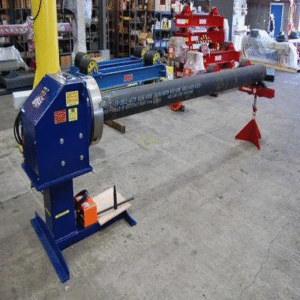
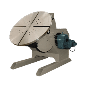
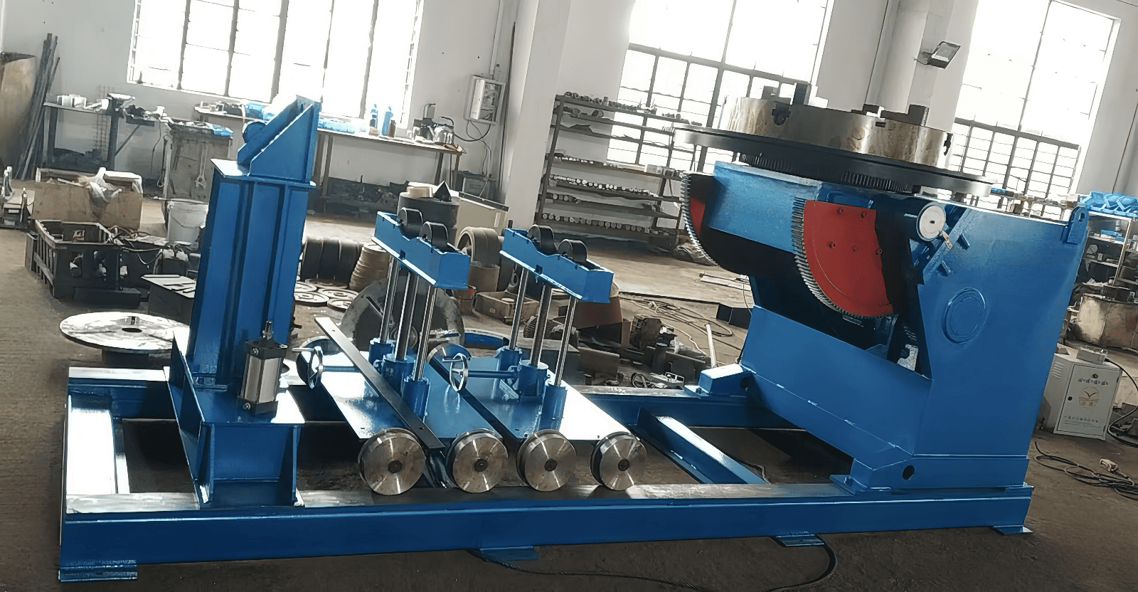
This resource covers the basics of blueprint reading, including the interpretation of welding symbols. - Top Welding Positioner Manufacturers and Supplier in China
- Guide for Types of Welding
Frequently Asked Questions (FAQs)
What is a seam weld symbol?
A seam weld symbol provides graphical information on a blueprint about the seam weld required for a particular fabrication project. It gives the location, size, type of weld necessary to join two pieces of base metal. Prior knowledge of this symbol shall enable a welder to carry out welding properly.
How do I read a weld symbol?
Reading a weld symbol involves understanding how it is constructed, typically consisting of a reference line, an arrow, and symbols on the other side or below that indicate the type and size of the weld, as well as any supplementary symbols. The information is passed down to the weld joint to specify precisely what the welder is required to do.
What are the different types of welds?
The basic welds in the welding process are: seam welds, fillet welds, groove welds, and spot welds. Each type serves a different purpose and is suitable for various applications in the welding process. For example, a groove weld symbol will indicate to weld two members edge-to-edge, whereas the fillet weld symbol will be employed for a joint perpendicular to the base metal.
What do the supplementary weld symbols indicate?
Supplementary weld symbols convey additional information on the welding, specifying the type of finish, backing-weld presence, and the like. This symbol is vital to confirm that the weld conforms to a specific requirement or standard of an organization such as the American Welding Society (AWS).
How can I tell the size of the weld and the length?
Behind every welding symbol lie the specifications of weld size and length. Traditionally, welders heed their measurements and perform welds to ensure strength and integrity. Proper calculations and measurements must be made, and the weld must be measurable to ensure accuracy.
What are some of the basic skills welders should have in reading weld symbols?
Basic welding skills are the ability to read welding symbols, identify different weld types, and know the welding process being used in fabrication. Lastly, welders must comprehend how to implement the methods according to the welding symbol instructions.


