
The mastery of MIG welder settings is a fundamental skill that yields clean, strong, and precise welds. Whether you are an experienced professional or a newcomer to the craft, adjusting wire speed, voltage, and other welding parameters is essential for optimizing performance and preventing common problems such as spatter, poor penetration, or inconsistent weld beads. This comprehensive guide demystifies MIG welding settings and offers practical insights and actionable tips to enhance your welding outcomes. We will explain how these parameters work together, address their impact on various metals and applications, and equip you with the knowledge to elevate your welding skills to the next level.
Understanding Gasless MIG Welding
Gasless MIG welding, also referred to as flux-cored arc welding (FCAW), does not require a shielding gas from an external source as it employs a flux-cored wire. The welding wire contains a flux that creates a protective atmosphere around the weld as it burns. This process is highly useful for outdoor welding or situations where gas might disperse due to wind. Gasless MIG welding is not only easily set up but perfect for thicker materials. On the downside, it might leave behind more spatter and slag, thus demanding additional cleanup effort. However, it is a suitable option for both amateur and professional welders who prioritize portability and convenience over the use of gas cylinders.
What is Gasless MIG Welding?
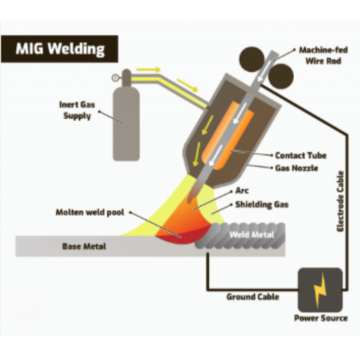
Gasless MIG welding, or flux-cored arc welding (FCAW), is characterized by the use of a flux-cored wire instead of an external gas. The flux inside the wire produces a gas shield and slag that protect the weld from contamination. This process is very suitable for use outdoors and in windy places where traditional shielding gases might not work effectively. Its portability, simplicity, and capacity to work with thicker metals have made it a frequent choice among both professionals and amateurs alike.
Differences Between Gasless and Traditional MIG Welding
| Aspect | Gasless MIG Welding | Traditional MIG Welding |
|---|---|---|
| Shielding Method | Relies on a flux core in the wire to produce a protective shield | Employs an external source of shielding gas |
| Usage Environment | Perfect for outdoor or windy conditions | Recommended for controlled indoor environments |
| Ease of Setup | More portable and easier to set up with fewer components | Requires additional equipment such as gas cylinders and regulators |
| Material Thickness | Excellent for thick components with deep penetration | More often used for thin or delicate materials |
| Weld Appearance | Can leave slag that requires removal | Usually cleaner with little or no post-weld processing required |
Advantages and Limitations of Gasless Techniques
✓ Advantages
- Portability: No external gas cylinder needed, making equipment more portable for remote or outdoor use
- Wind Resistance: The absence of shielding gas makes the process less susceptible to wind
- Deep Penetration: Excellent for working with thicker metals and structural applications
⚠ Limitations
- Slag Cleanup: Requires additional cleanup time to remove slag from weld beads
- Heat Control: Higher temperature may be incompatible with thinner or delicate materials
- Weld Appearance: Visual finish may not meet requirements for aesthetic projects
Key Factors Influencing MIG Settings
- 1
Material ThicknessThe aspect of the material being welded is of great importance in deciding the voltage, wire feed speed, and amperage. Thicker materials require higher voltage and amperage settings for proper penetration.
- 2
Wire Type and SizeThe kind and size of the welding wire should correspond to the material and application. Thinner wires are appropriate for thin materials while thicker wires can manage thick sections efficiently.
- 3
Shielding Gas CompositionWhen utilizing gas, the designation of the shielding gas has a direct impact on the arc characteristics and weld quality. For example, CO₂ gives deeper penetration while an argon mix guarantees cleaner welds with reduced spatter.
- 4
Welding PositionVertical or overhead welding usually needs lower voltage and wire feed speed compared to flat positions in order to maintain control and reduce dripping.
- 5
Power Supply SettingsEnsure that the voltage and amperage are suitable for the particular material and wire used. Settings too low may result in weak welds, while settings too high may lead to burn-through or excessive spatter.
- 6
Travel SpeedThe speed at which the welder travels determines the look of the bead and the depth of penetration. Rapid movement can result in lack of penetration, whereas slow movement can lead to excessive buildup.
Wire Size and Type
The wire size and type selection are very important for achieving proper welding results. Smaller diameter wires, for example 0.023-inch, are excellent for thin materials, providing more precision and less heat input. On the other hand, larger wires, such as 0.035-inch or 0.045-inch, can be used for thicker materials, providing deep penetration and strong welds. Furthermore, choosing the right wire type (solid or flux-cored) actually depends on the welding environment and the material being used. For example, solid wires give best results in clean areas, while flux-cored wires can be used outdoors in less prepared areas with less cleanliness. Always consider the thickness of the material, the joint design, and the welding position when selecting the best wire size and type for your job.
Material Thickness Considerations
The thickness of the material is an important factor when selecting the appropriate welding wire and settings. Thicker pieces of metal necessitate stronger current and bigger wire diameter to produce proper welds with good penetration. Conversely, using thin wire and low current for welding thinner materials prevents burn-through while keeping the work neat and precise. To produce excellent results, always adjust the wire size and machine settings according to the thickness of the material.
Understanding Polarity in Gasless Welding
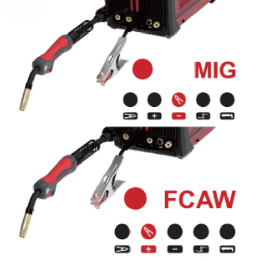
One of the main aspects of gasless welding is its polarity, which has a very strong influence on the weld’s quality and stability. In the case of gasless flux-core welding, Direct Current Electrode Negative (DCEN) is the standard method. This means that the electrode is connected to the negative side and the workpiece to the positive side. DCEN provides deeper penetration, less spatter, and more efficient operation of flux-core wires, thus being the best for projects where both accuracy and strength are needed. Check the wire manufacturer’s suggested polarity for the best results to avoid mistakes.
Interpreting the Gasless MIG Settings Chart
Understanding a gasless MIG settings chart requires proper attention to three main factors:
📏 Material Thickness
The thickness of the material will dictate the recommended settings by the chart. Thicker materials will need more voltage and wire feed speed for penetration, whereas thinner ones will require lower settings to avoid burns.
🔧 Wire Size
The wire size mentioned in the chart must correspond to your welding operation. Heavy-duty applications use thicker wires while lighter, thinner materials are worked on with thinner wires.
⚡ Polarity Settings
The chart will show the appropriate polarity. In gasless MIG welding, Direct Current Electrode Negative (DCEN) polarity is most commonly used, providing even heat distribution facilitating weld fusion.
Pro Tip: If you strictly apply these specifications from the chart, you will quickly, and with minimum mistakes, produce strong and clean welds. Always double-check the adjustments before you start to make sure you are following the chart correctly.
Overview of MIG Settings Charts
MIG settings charts are very important references that help welders decide the right parameters according to different materials and their thicknesses. These charts typically show wire feed speed, voltage, amperage, and polarity settings according to the type of metal and gas used. If welders follow the recommendations provided by the chart, they will get the best penetration, strong welds, and fewer defects, leading to a more effective and accurate working process.
Step-by-Step Guide to Using the Chart
Identify the Material
Before welding, determine the type and thickness of the material which is going to be welded. This is crucial information for choosing the proper settings.
Select the Wire and Gas Combination
The chart will guide you to the right wire and gas match for the material to be used.
Locate the Parameters
The chart will provide you with the recommended voltage, wire feed speed, and amperage settings that are specific to your material and gas combination.
Adjust Your Welder
Enter the suggested parameters into your MIG welding machine. It is common for machines to have voltage and wire feed speed adjustments that are easy to make.
Perform a Test Weld
A quick test weld should be performed to check the settings. Proper penetration and bead appearance should be the criteria for inspecting the weld.
Fine-Tune if Necessary
If the test weld reveals any imperfections, decrease or increase the voltage or wire feed speed slightly to get better results.
By following these steps, you can easily refer to the MIG settings chart and use it to produce strong and attractive welds.
Identifying Optimal Settings for Your Project
In order to determine the best MIG welding settings for your particular project, the first step is to check the MIG settings chart that came with your welder, taking into consideration the kind of material, its thickness, and the size of the wire. Then, connect these aspects to the suggested voltage and wire feed speed. Make a test weld on scrap material to confirm the settings by checking the penetration and bead quality. If necessary, make small adjustments but always keep a proper balance between heat and wire deposition so that you will get the weld strength and appearance you want. This systematic method guarantees precision and effectiveness of results that are specifically devised for your welding task.
Common Challenges in Gasless MIG Welding
⚠️ Key Challenges to Watch For
1. Spatter Accumulation
Gasless MIG welding usually produces more spatter than gas-shielded methods. If not well controlled, this can result in material loss and additional time for cleaning up.
2. Porosity Issues
If the right technique is not applied, gases trapped in the weld can form pores leading to weakening of the weld. The risk can be reduced greatly if the right wire feed speed and angle are used.
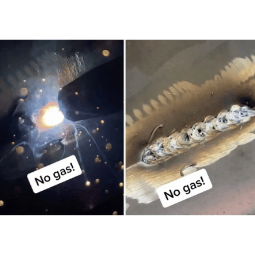
3. Limited Weld Appearance
Welds made with gasless wires may not be as smooth as those produced with shielding gas and, therefore, may not be suitable for projects that need a high level of aesthetic acceptance.
4. Welding Outdoors
Although gasless welding is the best choice for outdoor use since it does not get affected by the wind, weld quality might still be compromised if extreme wind or moisture occurs.
5. Wire Burnback
Wrong settings like incorrect voltage or wire feed speed can cause the wire to burn back which will damage the equipment and cause workflow interruptions.
By overcoming the mentioned difficulties with correct settings and proper practice, welders can make long-lasting and robust results in the gasless MIG welding process.
Addressing Spatter Issues
In gasless MIG welding, it is crucial to set the voltage and wire feed speed correctly, as improper calibration could result in more spatter. Use only very good and clean flux-cored wire and clean the working surface to prevent dirt accumulation. Moreover, try out different welding techniques, for instance, changing the travel speed and maintaining the gun angle constant, to get smoother results.
Achieving Clean Welds
✨ Best Practices for Clean Results
- ✓
Use quality flux-cored wire for consistent performance - ✓
Clean the work surface thoroughly to remove all impurities such as grease or rust - ✓
Ensure that your voltage and wire feed speed are properly set to avoid irregularities - ✓
Keep the same travel speed throughout the welding process - ✓
Maintain consistent gun angle for slow, secure, and accurate movements
Overcoming Thickness Challenges
In gasless MIG welding, one has to deal with thickness issues by setting their parameters according to the material’s thickness.
| Material Type | Recommended Approach | Key Considerations |
|---|---|---|
| Thicker Materials | Increase both voltage and wire feed speed for proper filling | Consider multiple passes and proper beveling for stronger welds |
| Thinner Materials | Use lower heat settings to avoid burn-through | Maintain high accuracy for travel speed and use weaving movements to distribute heat |
Reference Sources
- Miller Welds – MIG Welding: Setting the Correct Parameters
Provides paramount suggestions for desktop settings of MIG welding including the right kind of machine and its accurate adjustments. - Pinnacle Shop – MIG Welding Parameter Settings and Guidelines
A comprehensive guide that deals with all the factors affecting welding to set them perfectly for the desired results. - YouTube – Fix Your Flux Core Setup: The Complete Guide
A video guide revealing the intricacies involved in setting up the gasless MIG welding (Flux Cored Arc Welding) process.

