
Gaining the skill of welding, one would need to know about the weld symbols as one-to-one skill that is important for any professional or aspiring welder. Groove weld symbols among the symbols are prominently seen as one of the most essential and widely adopted for producing strong and precise joints in the structural and industrial applications. Nonetheless, interpreting these symbols can be quite a challenge at times and that too more so for people with less exposure to the field. Therefore, this guide is meant to bring light to the world of groove weld symbols, unravelling their parts and revealing their use in an understandable and implementable manner. By the time you finish reading this article, you will not only understand the importance of these symbols but also acquire the knowledge of how they contribute to welding accuracy and efficiency. This post will lead you to the successful welding whether you are trying to polish your skills or just need a little reminder.
Introduction to Groove Welds
Groove welds are characterized as such welds, used basically to get metal together by melting and pouring a material into the prepared joint groove between them. They are favored among construction and fabrication due to their strength and reliability. Groove welds are classified into several types, including single-bevel, double-bevel, and V-groove, each being appropriate for certain uses depending on the factors of material thickness and joint design. Such welds are still to be considered as the main factor for stability in constructions and are hence being extensively applied in such industries that demand high-strength bonds.
What is a Groove Weld?
A groove weld is a procedure of welding in which the edges of two metal parts are melted and fused together in a prepared groove or hollow space by pouring molten metal in between them. It guarantees a strong and permanent fusion, thus proving its importance in maintaining the stability of the structure in areas such as building and manufacturing.
Importance of Groove Weld Symbols
The symbols for groove welds are very important for effectively conveying the exact welding needs through technical drawings and for keeping the communication among the parties involved, such as fabricators, engineers, and welders, clear and consistent. These symbols show information like the type of weld, its size, shape, position, etc., and these are the very factors that ensure the construction’s ability to withstand loads and the design standards are not violated. By providing a common way to present information, grove weld symbols become a means of minimizing mistakes, making the manufacturing steps easier and faster, and thus, increasing project productivity in total.
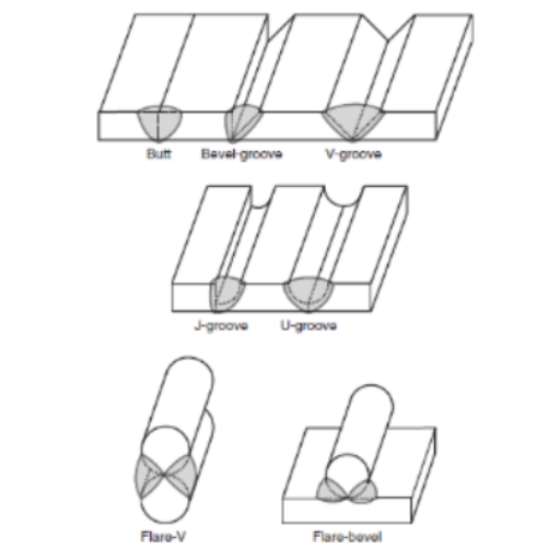
Overview of Common Weld Types
The different types of welding are very important in deciding the quality and usability of a connection. Among the most prevalent types are butt welds, which are used for end-to-end joining of two components; fillet welds, which are commonly used for joining two surfaces at a right angle; groove welds, which allow for deeper penetration and strength in thicker materials; and plug or slot welds, which connect overlapping pieces by means of holes. The choice of each weld type is made carefully taking into account the design specifications, material properties, and the use, thus providing the necessary strength and performance to the structure.
Understanding Weld Symbols
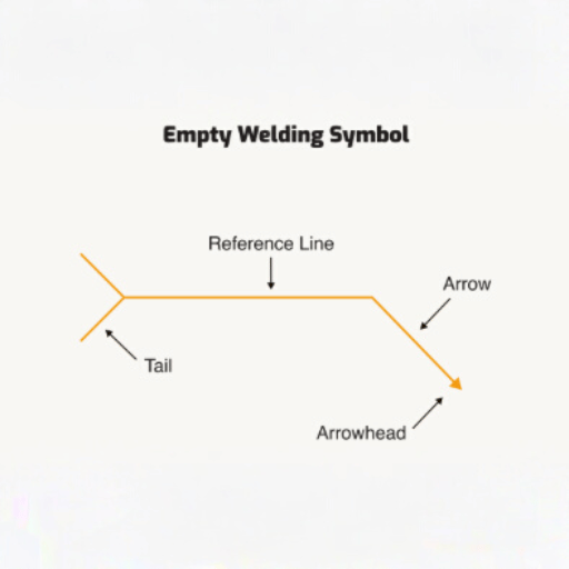
Weld symbols are a universally accepted method of referring to the welding requirements through technical drawings. They summarize the information of weld type, dimensions, position, and other criteria for successful welding in a compact form. The symbol consists of a main line, an arrow pointing at the location, and sometimes a tail for specific instructions. This method provides the distinctness and uniformity that let both the welders and engineers read and implement the drawings correctly.
Components of a Weld Symbol
The weld symbol is made up of three main parts:
- Reference Line: The horizontal line that forms the base of the symbol. It indicates with the help of various letters and symbols what kind of weld is to be done.
- Arrow: Indicates the precise location of the weld in the drawing, thereby marking the joint or area intended for welding.
- Tail (Optional): A place where further instructions or specifications are given, like for instance the type of welding process or other details.
All these elements produce an unambiguous and uniform way of communicating the welding requirements efficiently.
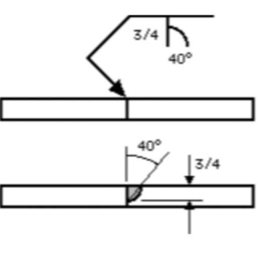
Decoding Groove Weld Symbols
The groove weld symbols indicate the necessary preparation and performance of welds which are usually applied to the edges of the two materials when joining them. The symbols contain the complete information regarding the weld such as the type of groove (e.g., V, U, J, square), weld size, depth of preparation, and others like root opening or groove angle. The details are shown on the reference line, and the modifiers and dimensions are there to make the welding process clearer. Correct reading allows for accurate welds to be done in accordance with the design and strength specifications.
Examples of Groove Weld Symbols
- V-Groove Weld Symbol:
Shows a V-groove, which is frequently used for thick materials where a single weld pass may not be adequate. - U-Groove Weld Symbol:
Indicates a U-groove, giving better penetration and less weld volume for thick sections. - J-Groove Weld Symbol:
Illustrates a J-groove, usually applied for joints with fewer welds passes and less prep work. - Square Groove Weld Symbol:
Represents a square-groove, proper for thin materials or when edge preparation is negligible.
All symbols come with exact dimensions and modifiers providing full description. This means that the weld’s preparation and execution will be reliable.
Types of Groove Welds
Groove welds are differentiated by the configuration and treatment of the joint. The primary classifications are as follows:
These types of welds help to choose the joint not only in terms of strength needed but also in terms of configuration of the joint.
Bevel Groove Weld
The process of bevel groove welding consists of making the edges of the materials to be connected at an angle, mainly in a “V” or one with a slope, so that a deep weld penetration is possible. This method works best for thicker materials and hence is used in numerous structural and heavy-duty applications due to its strength and durability.
V-Groove Weld
The welding of a V-groove is done by treating the edges of two metal pieces in a “V” manner prior to the application of heat. The resulting feature permits full penetration and ensures a sturdy connection, thus facilitating the use of the method for heavy materials and construction works.
U-Groove Weld
A U-groove weld is an operation in which the edges of the materials are shaped into a “U” profile before the actual welding process. The design is meant to decrease the filler material needed, lend deep penetration and strong bonding, and thus, it is suitable for thick plates and high-strength applications.
Key Parameters in Groove Welds
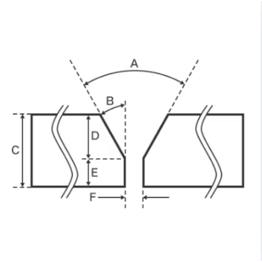
Understanding and controlling key parameters is essential for achieving high-quality groove welds. The following parameters significantly impact weld performance:
- Groove Angle: This is the angle between the edges of the pieces being joined. It has an effect on both the weld penetration and the strength of the weld.
- Groove Depth: This is the depth of the groove made in the material, which also affects the quantity of the filler material required.
- Root Opening: This is the space that exists between the edges of the workpieces at the bottom of the groove and is very important for allowing proper fusion.
- Root Face: This is the horizontal part at the bottom of the groove that helps to control the depth of the weld.
- Filler Material: This is the material that is added to the groove during the welding process, and its selection is based on the similarity with the base materials.
- Heat Input: This is the total heat that is supplied during welding, and it will affect the quality and life of the welded joint.
By controlling these factors precisely, groove welds can be made with the desired efficiency, quality and strength.
Groove Angle and Its Significance
The groove angle plays an essential role in deciding the joint’s access to the welding arc and the weld’s penetration, thus assuring the weld quality. Selecting the right angle gives a good combination of access and economy in terms of material use. Too large angles lead to a waste of filler material, whereas small angles might lead to a lack of fusion. Proper groove angle selection not only produces a strong and long-lasting weld but also reduces post-weld defects, which in turn affects the structural integrity of the joint.
Root Opening Considerations
The root opening, which is the space between the edges of a joint, is a crucial factor that determines the extent of weld penetration and fusion. The proper root opening size is influenced by the welding process, thickness of the material, and joint geometry. A very large root opening can result in wastage of weld metal and also cause defects like sagging or burn-through; on the other hand, a very small opening can lead to lack of penetration. Therefore, the right root opening must be obtained in order to produce a weld that is strong, free of defects, and meets the requirements for the structure.
Factors Affecting Weld Quality
Weld quality is affected by various factors such as material type, joint preparation, welding technique, heat input, and skill of the welder. The right choice of material and proper joint preparation, which includes cleaning and beveling, create a strong base for welding.
The use of a consistent technique and the control of heat input at the optimum level reduce the occurrences of defects like cracks, porosity, or lack of fusion. Moreover, the knowledge and accuracy of the welder are important in producing a dependable and high-quality weld.
Frequently Asked Questions (FAQs)
Reference Sources
- Open Oregon – Groove Welding Symbols: Describes usage of groove welds in butt joints and their cases in welding.
- TWI Global – Application of Weld Symbols on Drawings: Talks about how weld symbols indicate, from design to production, the necessary welding requirements.
- Structure Magazine – Commonly Misapplied Welding Symbols: Points out the issues misunderstanding the groove weld symbols brings about and their correct usage.
Conclusion
Mastering groove weld symbols is an essential skill for any professional welder or engineer working in structural and industrial applications. By understanding the components of weld symbols, recognizing different groove weld types, and carefully controlling key parameters such as groove angle, root opening, and heat input, you can ensure the production of strong, reliable, and defect-free joints. Whether you’re interpreting technical drawings or executing welds on-site, this comprehensive knowledge empowers you to maintain the highest standards of quality and safety. Remember that continuous practice and attention to detail will transform these symbols from complex notations into a natural language of precision engineering, ultimately contributing to the structural integrity and success of your welding projects.


