
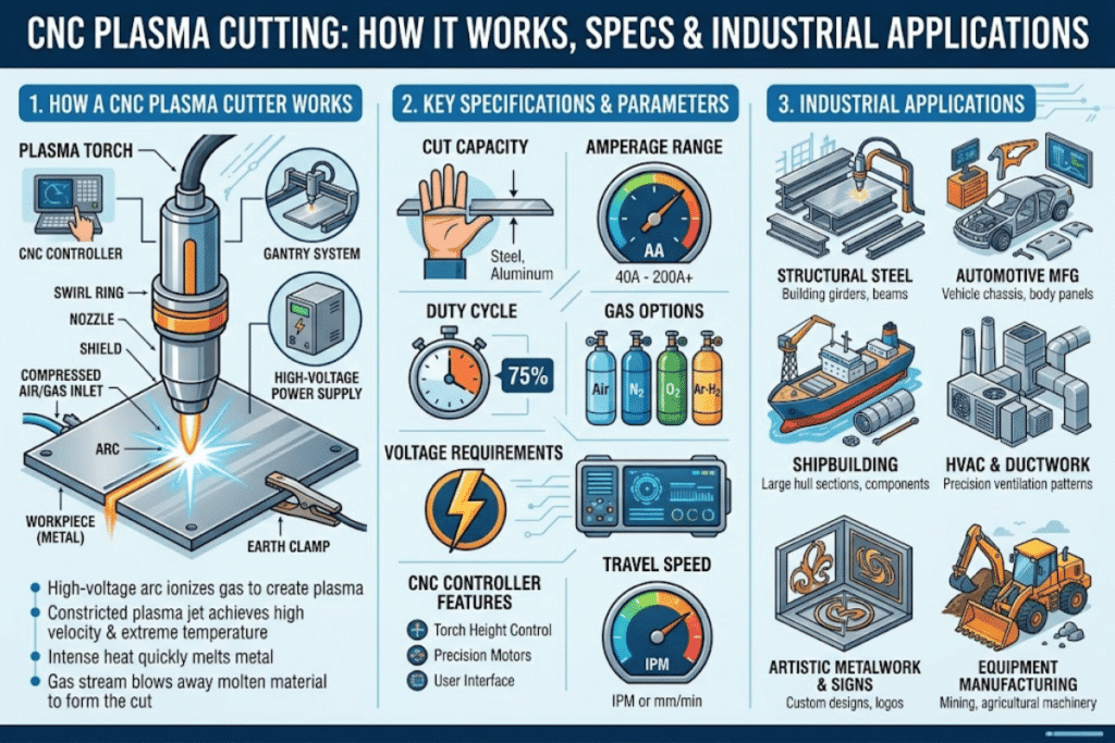
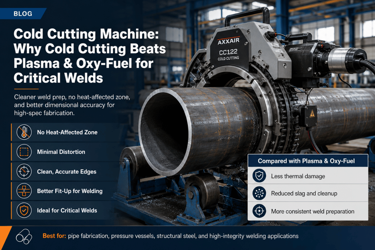
A cnc plasma cutter is a Computer Numerically Controlled (CNC) thermal cutting process utilizing a high temperature ionized jet of gas-plasma-to cut electrically-conductive metallic materials to fine tolerances, more precisely than any handheld method. For fabrication shops permanently cutting carbon, stainless, aluminum, and other sheet to 2″ plate thickness, it remains the industry standard: faster than o×y-fuel, less e×pensive than fiber laser through 6-50mm, and much more capable feeding torches into production lines than hand torches. This guide e×plores the way in which a CNC plasma cutter works, from the physics to the amperage classes encountered (“to the table size” as they say), to material capacity, air and electrical infrastructure shops so often overlook, real-world industrial applications, a brutally honest comparison to laser and o×y-fuel cutting, Bimosu economics that determine real operating costs, and the market outlook to 2026.
Quick Specs — CNC Plasma Cutter at a Glance
| Plasma arc temperature | ~25,000°F (~14,000°C) |
| Power class range | 45 A (light fab) – 200 A+ (heavy industrial) |
| Mild-steel cut capacity | 1/4″ (45 A) up to 2″+ severance (125 A+) |
| Typical kerf width | 1.5–3 mm depending on amperage and consumables |
| Edge bevel (standard plasma) | ±1–4° off perpendicular |
| Air requirement (typical 65 A) | ~6–7 SCFM at 80–90 PSI continuous, dried |
| Cuttable materials | Mild/carbon steel, stainless, aluminum, copper, brass — conductive only |
| Industrial frame lifespan | 10–20 years (consumables are wear items, not the machine) |
What Is a CNC Plasma Cutter and How Does It Actually Cut Metal?
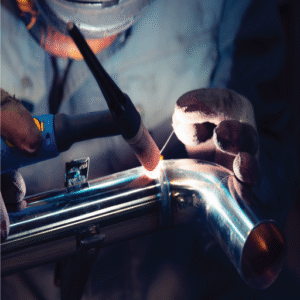
A bitonar s high-temperature cutting method involves directing a high-velocity jet of ionized (or. plasma). gas through a workpiece to cut metallic materials that conduct electricity. The word “MIG” in MIG-MPP is derived from the fact that the process uses an active arc to shield the metal being cut. This active arc develops from an arc transfer process between a power source and a tungsten ingots. The process produces a very precise cut at much higher speeds than may be achieved by [hand work].
How does a CNC plasma cutter work?
A typical plasma machine takes the shape of a torch mounted on a machined gantry that has three degrees of freedom and dedicated motion. A computer program, written as G-code from a CAD drawing and stored on a laptop, receives commands from the torch to move the plasma arc along a path in space; referring to it as “CNC” can identify one with a central file-serving commodity PC as distinct from any of several proprietary CNC control packages, perhaps with a touch screen for some operation modes.
- The inherent physics of the torch process go through a series of stages during each cutting cycle:
- High frequency ignition of a pilot arc between the electrode and the orifice of the torch pushes a pilot column of ionized gas through the process orifice and into the workpiece. This pilot arc has a time-averaged temperature of appro×imately 25,000 °Fahrenheit (14, 000 Celsius), hot enough to quickly produce the exact superficial change needed to slough away a fairly narrow kerf.
- When the arc touches bare metal, the pilot column extinguishes. The main column then makes the transfer from the orifice to the workpiece; from this moment on, the arc circuit runs through the metal. This transfer is what begins the actual cutting process.
- The arc melts the work at a defined rate, removing material from the plate; the high pressure (~25,000psi) kiln tends to eject the resulting plume of molten metal out of the bottom of the cut, with a force which depends on an interaction of the amperage, millisecond-by-millisecond MIG feed rate, two millisecond-by-millisecond torch travel speed, and multiple other factors. The balance, known as “gas cut quality” is critical to CNC control of edge shape, but can be addressed by the operator with the torch speed (as well as amperage and gas flow).
During the cut, the CNC reads encoder feedback from the high-dollar machine, adjusts torch position in X, Y, and Z, and maintains a path showing up on the goateed screen, while the torch height is constantly regulated by that arc transfer moment with a set of controls separate from any stepper stacks. This loop dropouts during cut may be so bad that torch height wanders by an unavoidable ½” until the system “reacquires” the plate. In production, the cap gets machined until the edges are offering 1-4 off perpendicular tolerances, a far cleaner level than is achievable with a Hand torch, or repeatable in a working day with a handcutout.
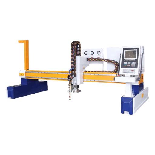
The Six Subsystems Inside a Complete CNC Plasma System
A completed cnc plasma cutter is not one box. It’s six subsystems that all have to function simultaneously, and knowing what each does makes a quote sheet easier to read and figuring out a service call a lot more straightforward.
- Contained within the cabinet is a power source that takes shop electrical service and converts it into the carefully regulated (via duty cycle – for example, 60 percent duty cycle equals six minutes of arc-on time for every ten minutes with the balance devoted to cooling) controlled DC arc.
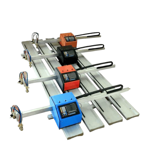
- Mounted to the gantry, a mechanized plasma torch takes the worker out of the concept of ‘hand.’ Hand torches can be retrofitted onto entry-level machines, but they severely limit repeatability. Professional fabrication make use of a torch explicitly designed for machine installation with consistent standoff geometry.
- The CNC controller – whether a dedicated industrial machine (Fanuc, Allen-Bradley, Siemens) or a Windows-based PC deployed as a hosting device pointed at the cutting software over Ethernet – takes care of reading the part program, driving the machine’s motors, and controlling input and output for arc-start signals. Many entry-level shops simply purchase a cnc machine connected to the system via Ethernet.
- Beneath the machine, a drive train is responsible for the movement of the gantry along the X- and Y-axis via servo or stepper motors with amplifiers and encoders, respectively, rack-and-pinion on the large industrial frame for the X axis (longer travel) and ball-screw on the Y. Z-axis travel is responsible for raising and lowering the torch independently of the rest of the system.
- Above the plate, an arc-voltage torch height control measures voltage as an indication of torch-to-plate distance and fine-tunes the Z-axis in real time. An absent or malfunctioning THC can result in a cut that skews during the product as the plate heats and warps.
- On the shop floor, the cutting table establishes the house – slats, frame, and either a water tank (dampening noise and fume and catching spatter) or a downdraft plenum (drawing up fumes into a filtering system). Deflection of the table directly correlates to one set of bevel errors in the cut.
Optional accoutrements include automated bevel heads for weld preparation, fume – extracting blowers, drill stations, marking heads, and pipe-cutting fourth axes. Each adds additional capability and complication in approximately equal measure.
Power Class and Cut Capacity: Decoding the Amperage Specification
Amperage represents the basic specification on every plasma cutting machine, and is the most easily mischaracterized one. The majority of potential buyers evaluate maximum severance thickness as the purchasing criteria – and that approach is flawed. Production thickness, duty cycle, and per-electrode product economics are the more significant factors.
| Amperage | Recommended Cut | Sever Capacity | Pierce | Best Fit |
|---|---|---|---|---|
| 45 A | 1/2″ (12 mm) | 7/8″ (22 mm) | 1/4″ (6 mm) | Sheet metal, signage, light fab |
| 65 A | 3/4″ (20 mm) | 1-1/4″ (32 mm) | 1/2″ (12 mm) | General job shop, mixed work |
| 85 A | 1″ (25 mm) | 1-1/2″ (38 mm) | 5/8″ (16 mm) | Heavy fabrication, structural plate |
| 105 A | 1-1/4″ (32 mm) | 2″ (50 mm) | 3/4″ (20 mm) | Industrial production lines |
| 125 A | 1-3/4″ @ 10 IPM, 100% DC | 2-1/2″ (63 mm) | 1″ (25 mm) | Heavy industrial, multi-shift |
| 200 A+ | 2″+ at production speed | 3″+ (75 mm+) | 1-1/4″+ | Shipyard, structural beams, heavy plate |
Capacity limits are representative of the industry-standard air plasma on mild steel for standard machine-torch consumables; stainless and aluminum reduce these limits by 15-25 percent. Sever values provide the maximum thickness that the system can cut through with production-quality edges.
The 4-Variable Power Class RulePower class is not taken on hardness alone. It is derived from four factors: (1) production tier (average thickness), (2) peak consumption requirements, (3) provided duty cycle at production amperage, and (4) consumable economics- when amperage exceeds 95% of credit nozzle rating the nozzles and electrode life drop precipitously. Just referencing max hardness results in Shop’s worst mistake: buying 125 A system to cut rare 1-3/4 plate then running at 65 A everyday—doubling consumable burn for parts a 65 A system would have cut at lower per-foot cost.
For shops cutting mainly 1/4″–3/4″ mild steel, a 65 A or 85 A system is almost always the right answer. Reach for 105 A or 125 A only when continual production above 1″ is on the order book. For a deeper specification breakdown including duty cycle behavior under continuous load, see our Plasma Cutting Technical Specifications.
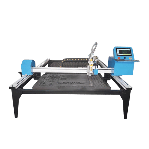
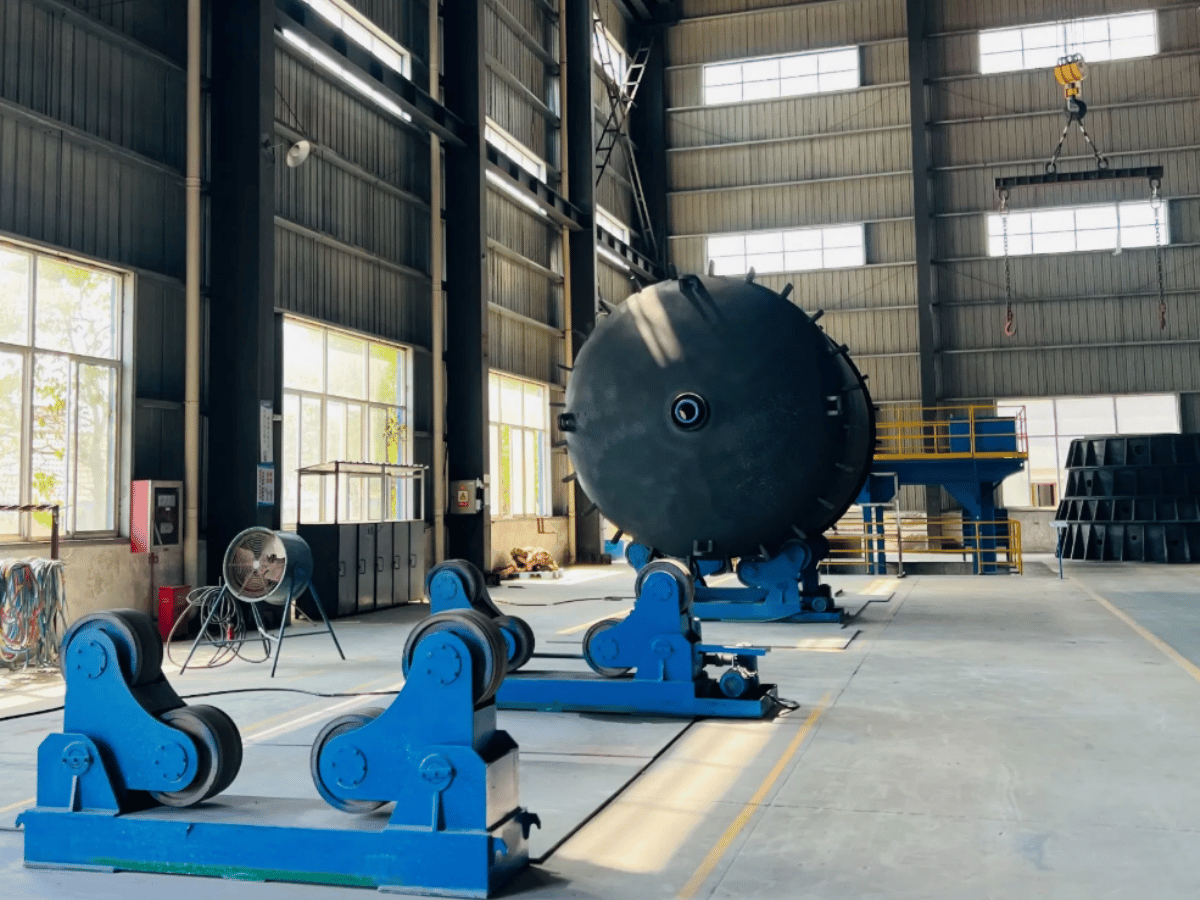
Cutting Tables and Workspace Footprint

Table size is determined by sheet stock; not cut size. A 44 (1.2 m 1.2 m) table just accommodates a half 48 sheet without re-clamping-which is okay for the cut but not for the workflow. Choose the table that swallows your most common stock without intermediate handling.
| Table Size | Sheet Stock Fit | Floor Footprint | Best For |
|---|---|---|---|
| 2×2 ft | Drops, signage blanks | ~6×6 ft including clearance | Hobby, art, prototype |
| 4×4 ft | Half sheet (4′×4′) | ~8×8 ft | Small fab shop, mixed work |
| 4×8 ft | Full standard 4′×8′ (1220×2440 mm) | ~8×14 ft | Industry baseline — 80% of fab work |
| 5×10 ft | 5′×10′ sheet, large brackets | ~10×16 ft | Heavy fab, structural shop |
| 6×12 ft | Oversize plate, beam flanges | ~12×18 ft | Shipyard, structural steel, wind tower |
Two substructure options exist once size is fixed. A water table submerges or pools water under the slats, absenteeism fume and noise as well as diminishing the heat-affected zone—favored for aluminum and stainless where rising oxidation is a concern. A downdraft table superimposes fume through perforated areas into a filtration system as well as keeping the shop air clean but mounting greater electrical service for the blower and continual filter replacement expense. Most high production studios with significant stainless content prefer a water table; high-volume mild-steel studios in clean environs prefer downdraft.
Map out for clearance: at least 4 ft of working room on each side of the table where there are no obstructionsplus a clear route for sheet administration. Tight sheet-metal welding subsequent processes are exclusively downstream of the cutting cell, so determine part flow before plumbing the air lines.
Materials You Can Cut and the Cut Quality You’ll Get
A CNC plasma can cut any metal that conducts electricity-that’s universal. Mild and carbon steels are the ideal target: swiftest cut speed, protracted consumable life, cheapest per foot. Stainless and aluminum both cut efficiently but with denser power and different consumable responses.
Can a CNC plasma cutter cut aluminum?
Yes, with a couple hitches. First, aluminum’s higher thermal conductivity wicks heat out of the kerf quicker than steel, denoting the effective cut capacity to an estimated 75-85% of the mild-steel classification- a 65 A system rated for 3/4 mild steel easily does approximately 5/8 aluminum. second, aluminum makes a tackier dross that bonds to the bottom edge; cutting submerged or with an air-airflame mixture alleviates the cleanup step, but doesn’t zero it. For the cleaniest aluminum sides, fiber laser is the optimal solution when resources are available.
| Material | Capacity vs Mild Steel | Recommended Gas | Edge Notes |
|---|---|---|---|
| Mild / carbon steel | 100% (baseline) | Compressed air or O₂ | Clean, weldable as-cut for most applications |
| Stainless steel | ~85–90% | N₂/H₂ mix or air (depending on grade) | Slight HAZ discoloration; passivation may follow on critical parts |
| Aluminum (5xxx, 6xxx) | ~75–85% | N₂/H₂ or air | Sticky dross on bottom edge, expect cleanup |
| Copper, brass | ~70% | N₂ or air | Reflective; high thermal conductivity narrows the working window |
📐 Engineering Note — Bevel and DrossManufacturing: standard plasma cuts will bevel 1-4 depending on torch height, travel speed, and which side of the kerf you measure. Typical convention: good side of the cut (opposite direction of gas swirl) should stay <2; scrap side might hit 4. When preparing weld parts with bevel on the join side, program for good side facing join (or get automated bevel head). When working with powder coating, plan for a dross- knockoff or grinder step- powder binds more readily to top spatter or bottom slag.
Air, Power, and Shop Infrastructure Requirements
The Air supply line is vastly underestimated in volume in every plasma shop. Constant flow of about 6-7 SCFM at 80-90 psi is what it takes to power a good plasma piercing. An 85 amp system draws more. An 85 amp single phase compressor nameplate rating of 14 CFM at 80 PSI that has a 55% duty cycle and is not a multi stage unit will feed 14 CFM only for a tiny fraction of a minute; the rest of the time, it is pulling 90% of its CFM at 15% of its capacity. Because excess air engenders a correspondingly weak, diffused arc, it costs the consumables every time the air supply leaves the sweet spot.
Moisture is the other half of the air supply challenge. Compressed air inevitably carries water and oil; they both will ruin the torch. A refrigerant or desiccant air dryer installed before a coalescing filter is the simplest, cheapest way to quadruple or more the consumables lifetime in an average shop.
| Power Class | Air Demand | Compressor Sizing (continuous) | Electrical Service |
|---|---|---|---|
| 45 A | ~5 SCFM @ 80 PSI | 5 HP single-stage minimum | Single-phase 220 V / 30 A |
| 65 A | ~6–7 SCFM @ 85 PSI | 7.5 HP two-stage | Single-phase 220 V / 50 A or 3-phase 220 V |
| 85 A | ~7–8 SCFM @ 90 PSI | 10 HP two-stage | 3-phase 220 V / 480 V |
| 125 A+ | 10+ SCFM @ 90 PSI | 15–25 HP two-stage with large receiver | 3-phase 480 V / 60+ A |
Fume extraction, eye protection, fire watch procedures, and clear-area guidelines are mandated as part of OSHA 29 CFR 1910.252. Process-level hot-work safety is detailed in AWS Z49.1, with ventilation specifically covered in AWS Fact Sheet No. 36. Any fume that contains chromium (stainless), beryllium, or galvanized coatings will require respiratory protection to EPA standards.
Industry practitioners understand that running too high above recommended pressure range diminishes the torch arc rather than strengthening it. Excess north of spec scatter the beam in the torch a fraction of a meter and undermine cut edge precision and depth. A manual’s pressure recommendation is not a minimum; it is the optimum.
Industrial Applications: Where CNC Plasma Wins
Plasma cuts a narrow niche in five uniquely suited industrial sectors where its unparalleled combination of speed, thickness range, and capital affordability can make every other choice irrelevant.
Structural Steel FabricationHigh-velocity flame and fine, rapid, upward gouge along 200-400A range bevel cuts and holes, curve and completely machine the edge of any grown Hull plate, bulkhead, or stiffener (thickness range 6-50mm). Acceptable bevel quality for most weld preps; use a gravimetry pass or grinder to finish in the stiffener range. Program to keep the high end of your preferred thickness zone facing the kerf.
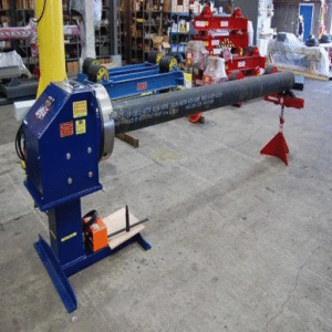
Shipbuilding and Yard WorkRapid throughput of punched, reinforced, turned, drilled, or otherwise pre-fabbed large assemblies and/or heavier plate components (ship hulls, modules, ship/assembly floats, etc. thickness 125-200 A) with 1-4 bevels plus multi axis bevel head and gravity aligned multiple torch systems in the torch. Use downstream welding rotators and tilting positioners, coupled to high-end CMM measurement systems, to rob the cutting bed of massive pieces.
HVAC and Sheet-Metal DuctworkFast, reliable production of tin-plate blanks, tabbed seams, critical-shaped parts (bolts, square-plate, trimmed bare hinge portions, tabbed flash, panel reinforcements, etc.) from light gage galvanized sheet, up to 60″ in the sheet, using 45 A hyper high- feed rate torch where part transfer speed outruns cutting speed.
Agricultural and Heavy EquipmentFrames, brackets, blade and tine blanks, hopper plate. Plate work in mild steel, 6-25 mm dominated. 65-105 A territory; bevel and dross matter less because parts get welded into assemblies rather than presented as finished surfaces.
Automotive Chassis, Trailer, and Body PanelsFrame rails, gusset plates, custom trailer beds, rock-crawler bumpers. Mixed thicknesses from 16-gauge sheet up to 1/2 plate. Mid-power systems (65-85 A) handle most jobs; trailer and chassis fabricators standardize on 48 tables for stock fit. Industrial-grade plasma cutting machines with downdraft tables keep the shop air cleaner during high-volume runs.
Plasma vs Laser vs Oxy-Fuel: The Honest Cross-Process Comparison
The 6 mm thickness mark is roughly where the cross-process trade-off shifts. Below 6 mm, fiber laser owns edge quality and speed. Between 6 and 50 mm in conductive metals, plasma defends its territory on cost-per-foot and capex. Above 50 mm in carbon steel, oxy-fuel still wins on raw cutting cost, even though edge quality is poor.
| Dimension | CNC Plasma | Fiber Laser | Oxy-Fuel |
|---|---|---|---|
| Thickness sweet spot | 6–50 mm conductive | 0.5–25 mm, best <6 mm | 25–200 mm carbon steel only |
| Edge quality | ±1–4° bevel, light dross | ±0.5°, near-net | Rough, requires cleanup |
| Cut speed @ 1/4″ mild steel | ~80–120 IPM (85 A) | ~200–400 IPM (4 kW) | ~16–24 IPM |
| Capex (turnkey) | $15K–$200K | $80K–$500K+ | $5K–$30K |
| Operating cost | ~$0.10–0.30/ft | ~$0.05–0.15/ft (lower at high volume) | ~$0.08–0.20/ft (oxygen + fuel gas) |
| Materials | All conductive metals | All metals + reflective challenges | Carbon and low-alloy steel only |
3-Question Process Picker
- What is your dominant material thickness? Under 6 mm with edge quality demand fiber laser. 6-50 mm conductive metals plasma. Over 50 mm carbon steel oxy-fuel.
- What is your peak monthly cut volume? Under 200 hours of arc-on time per month, plasma’s lower capex usually wins. Above that, fiber laser’s lower per-foot cost amortizes.
- How much non-ferrous (stainless, aluminum) is in your mix? If >30% non-ferrous and edge quality matters, fiber laser is worth the capex premium. If non-ferrous is occasional, plasma’s flexibility wins.
For a deeper side-by-side cut-quality comparison with sample edges and per-process cost-modeling, see our plasma cutting vs laser cutting analysis and the alternative angle in comparing laser cutting vs plasma cutting.
Operating Cost and Consumable Life: TCO Reality Check
Industrial plasma cutting machines are 10-20-year assets. Consumables are wear items, replaced on schedule. Total cost of ownership is dominated by the consumable burn rate – which is dominated by operator practice, not the machine label.
What is the life expectancy of a CNC plasma cutter?
On industrial-grade equipment, the mechanical frame and motion system typically run 10-20 years before significant rebuild. Properly maintained power sources deliver a similar service life. torch consumables – electrode, nozzle, swirl ring, retaining cap, and shield – are wear items that get changed every few hours of cutting time. “Lifespan” is therefore really two questions: machine asset life (decade scale) and consumable replacement cycle (hours-to-days scale).
| Consumable | Typical Life | Replace When |
|---|---|---|
| Electrode (hafnium-tipped) | 800–2,000 pierces | Hafnium pit deeper than ~1.5 mm |
| Nozzle | 600–1,500 pierces | Orifice no longer round, internal gouges visible |
| Swirl ring | Long — replace only on damage | Cracks, arc burns, dirt-clogged holes |
| Shield | Reusable after cleaning spatter | Visible deformation or burn-through |
| Retaining cap | Service life of the torch | Damaged threads or burn marks |
“Best cut quality and parts life is usually achieved when the amperage is set to 95 percent of the nozzle’s rating. If the amperage is too low, the cut will be sloppy. If it is too high, the nozzle life will suffer.”
— Hypertherm Technical Service, “10 common plasma arc cutting mistakes”
consumable economics are decided by four operator-controlled variables: pierce height, air quality, amperage discipline, and lead-out programming. Pierce too low and molten metal sprays back onto the nozzle face. Use unfiltered moist air and the electrode hafnium pits prematurely. Run amperage above 95% of nozzle rating chronically and nozzle life halves. Program lead-outs that keep the arc on past the cut and arc-stretching damages the nozzle interior. None of these are the machine’s fault and none are listed on the spec sheet.
Pierce at 1.5-2 times the recommended cut height. By far, the most premature nozzle failures, on shop-floor reports, trace directly back to this one setting. If your THC is lowering the torch into cutting height before the pierce has finished, your nozzle is being abused – “skittish cuts” almost invariably turn out to be consumables, not mechine.
Limitations and When CNC Plasma Is the Wrong Choice
Plasma is the best choice for a wide variety of parts but not for all cutting work. 5 constraints fix the perimeter.
- Operating tolerances below 0.5 bevel are out of reach. Batch plasma runs at 1-4; highspec plasma at 0.5-1 on a hot day, on a microwave. Operating tighter in the short term and elsewhere calls for fiber laser, waterjet, or post-cut machining.
- Very narrow gauge below 16 ga (~1.5 mm) is technically feasible but seldom the correct choice. As Gauzeiron and others have shown, HAZ becomes correspondingly maximized, edges out-cheap rainbow purple/blue/breathe-in sparkle more than fiber laser does. Plasma isn’t hopeless – just not quite best.
- Non-conductive stock just will not cut. Plastic, glass, fiberglass, ceramics – they all avoid plasma’s arc entirely. Waterjet or laser is the choice.
- Tight internal corners and tiny holes bump against internal kerf-geometry limitations. The kerf width (1.5-3 mm) and pierce-dome width lock out the tiniest hole and tightly-matched internal radius for a standard plasma. (Dubiety threshold: holes smaller than plate thickness are nearly assured under consistent, not just average, process conditions.)
- Fume load is real and can’t be ignored. Per meter of product, plasma generates more visible fume than fiber laser. An increase in chrome or zinc content in the material – stainless, painted, galvanized, coated – elevates the fume, requiring respirators and a larger filtering unit.
Fabricators might purchase plasma for the wrong reasons and discover the limitations too late: “we bought plasma to do everything from sheet detail to plate cutting” usually followed by a second purchase a fiber laser, to accomplish what plasma failed. Regular occurrence makes it straightforward to budget two machine choices, not one.
CNC Plasma Cutting Market Outlook 2026
Plasma is not succumbing to the second coming. Market research indicates expansion, fiber laser captures certain applications plasma already played weak, and the current ranked market segment for plasma remains CNC.
According to Global Market Insights, the plasma cutting machine industry exceeded USD 811.4 million in 2025, expanding at a 5.9% compound annual growth rate through 2034. A separate forecast projects 4.5% CAGR through 2030. Both analyses agree on the same direction: growing, not shrinking.
Three technology shifts are shaping 2026 buying decisions:
- Highend plasma is ablating the laser space. X-Definition and comparable systems are now approaching edge quality similar to fiber laser on medium-thickness mild steel, preserving plasma’s fee stream at above 6 mm.
- Industrial tier continues to adopt the Web of Things and advanced schedule maintenance. Modern systems more than ever imparts data on consumable opportunity, working cycle, and arc voltage to plant maintenance tools – reducing unexpected and downtime and supporting costs-by-part.
- Automated angles cutting heads are transitioning from an “elite” to midrange occurrence. 5-axis angles heads with weld-approbate angle programming have been noted one way or another on structures and pressure container fabrication.
If you are planning a 2026 capital purchase: budget for a HD or X-Definition class system if mid-thickness mild steel is your dominant work. If you are buying for sub-6 mm sheet metal in volume, run the numbers on fiber laser before falling back to plasma. And in either case, schedule an air-system audit before the cutting machine arrives- air quality is what determines whether the consumable budget hits the projection.
Frequently Asked Questions
Q: How big of a compressor do you need to run a plasma cutter?
View Answer
Q: What is a disadvantage of CNC plasma cutting machines?
View Answer
Q: How accurate are CNC plasma cutters?
View Answer
Q: Can you make money with a CNC plasma cutter?
View Answer
Q: What is the difference between a CNC plasma cutter and a CNC plasma table?
View Answer
Q: How do you program a CNC plasma cutter?
View Answer
About This Analysis
This article combines specifications from public Hypertherm Powermax SYNC cut charts, FHWA structural-steel research on the behavior of plasma-cut holes, OSHA and AWS hot-work standards, and operator experiences from the industrial fabrication forums. Capacity and consumable numbers are typical for industrial equipment; particular machine and material pairs may vary. Peer reviewed in April 2026 by the Resizeweld engineering team.
References & Sources
- OSHA 29 CFR 1910.252 — General Requirements for Welding, Cutting, and Brazing — U.S. Department of Labor, Occupational Safety and Health Administration
- OSHA Welding, Cutting, and Brazing Standards Index — U.S. Department of Labor
- Evaluation of Holes Fabricated Using Plasma Arc Cutting (FHWA-HRT-20-056) — U.S. Federal Highway Administration
- NIST Special Publication 847: Machining of Advanced Materials — U.S. National Institute of Standards and Technology
- AWS Z49.1 — Safety in Welding, Cutting, and Allied Processes — American Welding Society
- AWS Safety and Health Fact Sheet No. 36: Ventilation for Welding and Cutting — American Welding Society
- Plasma Cutting Machine Market Size, Forecast Report 2026–2035 — Global Market Insights
- Plasma Cutting Machines Market Outlook 2026–2030 — GlobeNewswire / Research and Markets
Related Articles
- Plasma Cutting vs Laser Cutting — cut-quality, speed, and cost comparison with sample edges
- Comparing Laser Cutting vs Plasma Cutting — alternative angle on the same trade-off, focused on capex amortization
- Types of Welding Compared — matching welding processes to plasma-cut blanks downstream
- Welding Sheet Metal — downstream welding considerations for plasma-cut sheet parts
- What Is a Beveling Machine — weld-prep beveling beyond the angles plasma can deliver natively
- Plasma Cutting Machines — Pillar Page — full system specifications and configuration options

