
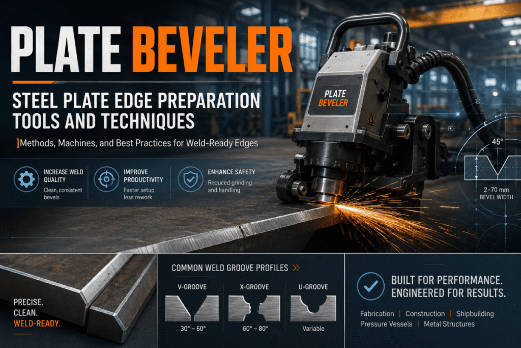
A plate beveler is a machine tool – portable or stationary – that puts an accurately angled face on a steel plate edge and prepares the weld groove geometry specified by AWS, ASME, or IACS codes before a joint is made. Proper edge preparation ensures full weld penetration, proper filler metal fusion, and structural joint integrity long before the service life is over – regardless of welder skill.
This primer will inform you of everything fabricators and weld engineers need to understand about groove preparation: 3 types of plate beveling machines, new standards for bevel angles, a step-by-step procedure, the heat balance of cold versus thermal, peer-reviewed data, and a tool selection decision tree.
What Is a Plate Beveler?
A plate beveler is a machine tool that, installed either permanently or on portable stands or carts, detaches the desired amount of material from the piece of steel edge along the full length, at the desired angle between 10 and 45 degrees. Unlike angle grinders used by many fabricators with little engineering oversight, a plate beveling machine, whether it be a shear wheel, knock-down punch, or indexable carbide inserts operates with a mechanical fence, an indexing gage, or a dedicated bearing, to produce a known, measurable, uniform A-field throughout each weld.
Edge preparation is defined by the weld code as creating the desired area of metal to be melted during welding. Milling and beveling machines are the modern standard for achieving this geometry precisely and without thermal distortion of the base material.
What tool makes beveled edges?
Selecting the right plate beveling tool depends on who, how many, and where. For production weld prep of steel plate in strict code, rule, and specification compliance, the three most common types of machine tools are roller shear or peeling machines, punch or nibbler-type, and carbide insert mills/banders. While angle grinders or hand-powered saws are occasionally used to break long runs of mild steel, offset “single pass” approaches cannot maintain the consistent geometry or the nominal land dimension necessary for primary weld quality.
An angle grinder is a handheld tool used broadly for grinding and fettling along welds. A weld prep machine is required for accurate, consistent, code conventional plate beveling; in the last 3 decades, many fabricators have moved from heavy handheld grinding, to dedicated plate beveling machines – with the added job cost benefit of avoiding HAVS: hand arm vibration syndrome caused by long term use of vibrating grinders.
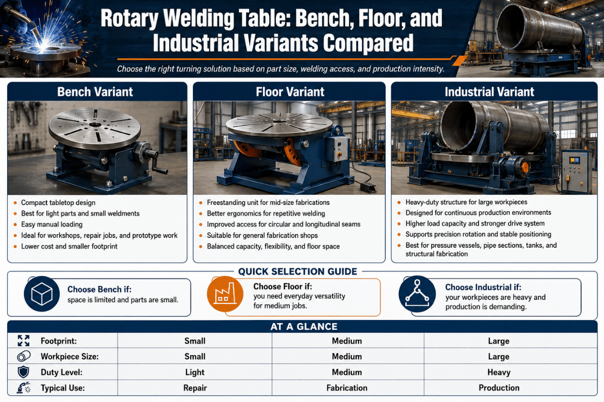
The 3 Main Types of Plate Beveling Machines Compared
Steel plate cold beveling, in the most commonly found methods today, uses three distinct cut-head principles, and each has strengths and application bands. When considering one of these machines for purchase, labor or service shop, or rental use, the differences are important to understand.
| Method | Speed | Plate Thickness | HAZ | Best For |
|---|---|---|---|---|
| Milling & Routing | 3–6 FPM | ¼″–4″+ (6–100 mm) | None | Thick plate, SS, AR steel, Duplex, Inconel |
| Punch & Nibble | 4–6 FPM | 3/16″–6″ (5–150 mm) | None | Portable use, curved/contour edges |
| Peel & Shear (Roller) | Up to 10 FPM | ¼″–1.5″ (6–38 mm) | None | High-volume straight runs, thin-medium plate |
Speed and thickness data: Gary Sheridan (TRUMPF) / The Fabricator, 2004; Rodney Plowe (Koike Aronson) / The Fabricator, 2011. Thermal methods (plasma, oxy-fuel) are covered in Cold vs. Thermal Beveling.
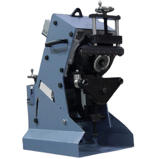
Milling (carbide inserts on a rotating multi-edge head) and routing are the most versatile methods of cold machining and produce precision, high quality edges at high speed on mild steel, wear resistant, all grades of stainless, zirconium, or Monel. Expect insert wear on average every 200 feet for a structural steel type steel (A36) grade, 50 feet on stainless, and over 600 feet on mild.
Punch and nibble bevelers employ a reciprocating punch approach. They provide access to the broadest plate thickness spectrum and contour edges inaccessible to fence-guided machinery. Reciprocativity produces more operator fatigue on a run, and consumable replacement seems to be less available than indexable carbide inserts. For maximum straight-edge beveling production, almost all fabricators choose rotary milling type for uptime and uniformity.
Peel and shear (roller shear) machines produce the fastest straight, thin-to-medium thickness plate beveling. A not-much-faster slowly rotating shear wheel shears a continuous chip at up to 10 FPM-generally the lowest cost operation per linear meter of bevel compared to machine methods-for-certainly the widest range of materials and stock thickness. One drawback is a limited material and thickness spectrum, and a degradation in weld-edge quality-it is rougher than milled edges-which is still weld-ready.
Read about types of beveling machines in detail, including stationary versus portable
Plate Beveler Specifications: Bevel Angles and Welding Standards
Bevel angle is not a preference-it is a specification. Your groove geometry must match the welding standards for bevelling and the applicable structural or pressure vessel code. If you get bevel angles wrong, you either have too much filler (costing time and consumables) or not enough penetration (a weld rejection).
| Bevel Angle (half-angle) | Groove Type | Typical Application | Standard |
|---|---|---|---|
| 22.5° (45° included) | Single bevel V-groove | Tight-access joints, thin plate | AWS D1.1:2025 |
| 30° (60° included) | V-groove | Shipbuilding, light structural, API pipeline | IACS / API 1104 |
| 37.5° (75° included) | Standard butt weld V-groove | Structural steel, pressure piping — most common | AWS D1.1:2025, ASME B16.25 |
| 45° (90° included) | Heavy plate butt, T-joint | Thick structural plate, heavy fabrication | AWS D1.1:2025 |
| Double bevel (X-groove) | Both faces beveled | Plate >25 mm — reduces filler volume vs. single V | AWS D1.1:2025, ASME Sec. VIII |
AWS D1.1:2025 (Structural Welding Code – Steel, 23rd edition) states a bevel land of 1/16-3/32 (1.6-2.4 mm) for prequalified V-groove and bevel groove weld joints. A proper land prevents burn-through at the root pass. AWS D1.1:2025 allows a 5 tolerance for groove angle (Clause 5.22). Always check project drawings and the Welding Procedure Specification (WPS) before setting up machine depth stops.
What is the standard bevel angle for welding structural steel?
There is no such thing as a universally mandatory bevel angle and this is the most common misunderstanding in the field. AWS D1.1:2025 defines a range of prequalified groove joint details for V-groove, bevel groove, J-groove and U-groove configurations, each with variable angle range. 37.5 for structural butt welds (half-angle) produces 75 included angle V-groove, but 22.5, 30, and 45 are fine for the same code prequal joint. Always consult WPS.
How to Bevel a Steel Plate for Weld Preparation
A plate beveling machine will produce a code compliant bevel only if the set-up and process steps are followed. Careful regard must be given to preparation before, during, and after the cut.
Application case: a structural steel fabricator beveling 25 mm A572 Grade 50 plate for a butt weld-to AWS D1.1:2025, WPS specifying a 37.5 bevel angle with a 3/32 land. Seven steps to weld code compliance:
- 1.
Inspect and clean the plate edge. Remove mill scale, rust, paint, and oil from at least 25 mm from the bevel edge. Contaminants cause premature carbide insert wear and introduce weld porosity. - 2.
Verify the WPS bevel angle and land dimension. Confirm the required bevel angle (e.g., 37.5°) and bevel land (e.g., 3/32″). Confirm your machine head can achieve this in a single pass or planned multiple passes. - 3.
Set the bevel angle on the machine head. Use the machine’s angle scale or an independent digital protractor to confirm the cutter head is set to the specified bevel angle. On milling-type machines, verify insert orientation for the correct cutting geometry. - 4.
Set the bevel depth stop to preserve the land. Adjust the depth fence so the machine removes material only to the required bevel depth, leaving the land dimension (1/16″–3/32″) intact at the plate root edge. - 5.
Clamp or support the plate securely. The plate must not move during the cutting pass. For automatic feed machines the plate lies flat against the guide fence; for portable machines, clamp the plate to the workbench with the edge accessible. Unsecured plates cause chatter and uneven bevel depth. - 6.
Execute the first pass at a controlled feed rate. Start at a moderate feed rate — below maximum — for the first pass, especially on stainless or wear-resistant steel. Consistent feed rate produces consistent bevel geometry. Chatter noise indicates feed too fast or a dull insert — stop and index or replace before continuing. - 7.
Inspect the bevel: measure angle, depth, and land. Use a weld gauge or digital bevel protractor to verify angle (within ±5° per AWS D1.1:2025 Clause 5.22), bevel depth, and land dimension. A clean, burr-free, oxide-free milled bevel is immediately weld-ready — no secondary grinding required. - 8.
Verify fit-up before welding. Fit both plates together and confirm the root gap matches the WPS. Welding fit-up is where correctly beveled plates most often fail in practice — poor fit-up wastes the precision of the bevel. Adjust gap with tack welds or fit-up clamps as needed before the root pass.
What are the most common mistakes when beveling steel plate?
Step 1: set machine depth to reach 3/32-45 on the job. Start cut. Step 2: functioncheck controls to advance at 4-6/minute. Step 3: doublecheck land 1/16-3/32 on the job. Step 4: run and visually check profile. Step 5: functioncheck controls to continue cut. Step 6: finish the cut and discard. Step 7: report machine for scheduled service. Do not bevel to a knife edge-avoid not achieving specified weld root land.
Error 2: Improper clamping on a portable punch/nibble machine. When a portable punch style beveler does not clamp positively against the edge of the plate, the punch can pull himself downward on the down stroke and break the cutter head; an all too common, expensive failure. This is one of the primary reasons seasoned fabrication shops choose rotary (milling) type machines for extended runs: they can compensate much more readily for edge variations and operator fatigue.
My third mistake was assuming that a correct bevel angle assured correct weld penetration. A correct bevel angle sets up the geometric situation needed for full penetration. It does not ensure it.
Welding parameters, the amperage, travel speed, root pass technique et al, all must be coordinated with the groove geometry per the WPS. A beveled joint with the right geometry but poor welding technique will still not pass NDT inspection.
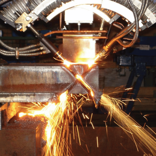
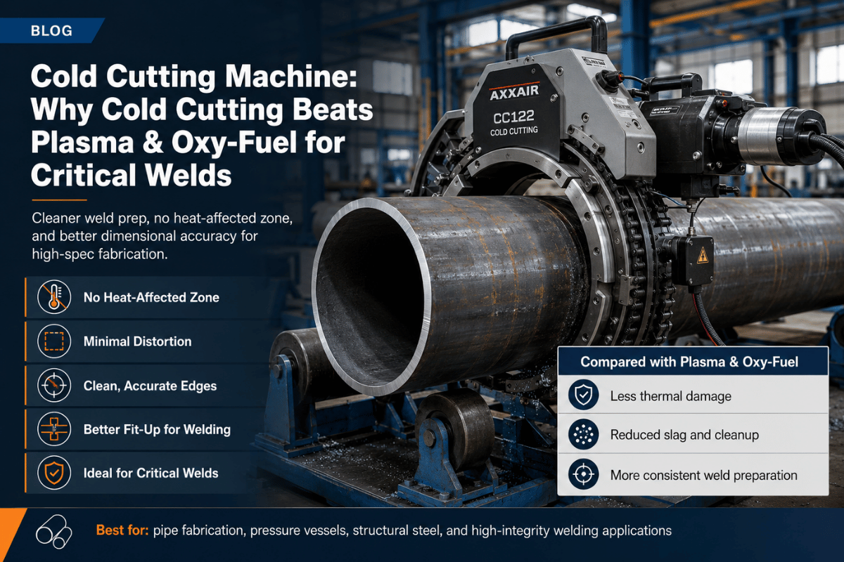
Cold Mechanical vs. Thermal Beveling: The HAZ Hidden Cost Framework
For mechanical beveling, the most frequently cited advantage of plasma as opposed to mechanized plate beveling was availability of equipment as well as perceived speed advantage. Less commonly cited in the shift back to mechanized beveling were downstream effects of the heat-affected zone (HAZ) metallurgical changes, oxide cleaning labor on stainless and high strength steels, and decreased carbide insert life on any resuming milling operations on to thermo cut edges.
| Criterion | Cold Milling | Plasma Beveling | Oxy-Fuel Cutting |
|---|---|---|---|
| HAZ thickness | None | 1–3 mm | 2–3 mm ¹ |
| Edge hardening | Zero change | Often >450 HV (S355 grade) | 250–450 HV1 (S355J2N, measured) ¹ |
| Surface roughness (Ra) | Machine-grade (excellent) | Good (modern HD plasma) | 6–10× rougher than milling ¹ |
| Weld-ready immediately | Yes | Often no — oxide cleanup required (especially SS) | No — oxide removal always required |
| Speed at 50 mm (2″) thick, 45° bevel | 3–6 FPM (milling) | 9–10 IPM at slow production rate ² | Slower; multiple passes for complex profiles |
| Impact on downstream carbide tooling | None | HAZ significantly shortens insert life ³ | HAZ + oxide layer damages tooling ³ |
| Fume and gas generation | None — chips only | Significant — extraction system required | Significant — ventilation required |
| Total cost at EU average labor rates | More economical ¹ | Higher — oxide cleanup + extraction infrastructure | Comparable at low volume; higher at EU wages ¹ |
¹ Kawiak & Sajek (June 2025), Advances in Materials Science 25(2):17-35. DOI: 10.2478/adms-2025-0007. S355J2N structural steel, plates 8–20 mm, angles 30° and 45°. ² Plowe / The Fabricator (2011): 400A system achieves ±45° in 2″ plate at 9–10 IPM — the slow end of practical production. ³ Experience: “carbide cutters don’t last long on the HAZ on plasma-cut edges” — machinist, Practical Machinist forum.
The plasma vs. cold milling cost comparison is often based on having a one sided shot, an incomplete comparison. The usual comparison considers just the machine cycle time. The whole picture should show:
- Oxide grinding labor after plasma on ss and high strength steel (labor that takes away most of the speed advantage)
- The faster the carbide insert wears, the more wear will be carried onto any downstream operations such as milling or drilling on plasma-cut edges -H AZ hardening of 250-450 HV 1 is significantly harder than the original plate.
- Capital and operating cost of fume extraction ( required for plasma and oxy-fuel but zero for cold milling)
- Weld rejection rate variance – Increase in the extent of HAZ hardening due to welding of S355 and higher grade materials associated with greater levels of porosity, risk of cold cracks and occurrence of fatigue failures under cyclic loading
- Peer reviewed cost analysis (S355J2N, 2025): at Polish labour rates (~17.30/hr), both process are cost ~2/m. At EU average rate (~33.50/hr), milling is cheaper.
For stainless steel, duplex, Inconel, and high strength structural steels (S690, AR plate, S960) cold mechanical beveling is the clear technical decision. Plasma deposits a chromium dioxide on stainless, requiring extensive grinding of the weld prep, negating any productivity gains. A cold milling and beveling machine produces an oxide-free, ready to weld surface with zero secondary operations. See also: beveling and chamfering — key differences.
Industry Applications of Plate Bevelers
Application of the correct plate beveling varies with industry. Each industry has designated standards that dictate the minimum bevel geometry, material considerations and edge quality requirements. Applying the incorrect beveling process – especially a thermal process where a cold mechanical process is required – can cause weld qualification failures and structural non-conformances.
| Industry | Governing Standard | Plate Thickness | Bevel Angle | Notes |
|---|---|---|---|---|
| Structural Steel | AWS D1.1:2025 / AISC | 6–50 mm | 22.5°–45° | WPS governs; most common plate beveling application |
| Pressure Vessels | ASME Section VIII | 8–100 mm | 30°–37.5° | Full-penetration CJP welds; J-bevel on thick plate reduces filler volume |
| Shipbuilding | IACS / Lloyd’s Register | 12–50 mm | 30°–45° | High-volume straight runs; cold milling preferred for classification society inspection |
| Offshore / O&G | DNV-OS-C101 / API 1104 | 15–80 mm | 30°–45° | Fatigue-critical; HAZ hardening especially problematic in seawater corrosion environment |
| Nuclear / Aerospace | ASME Sec. III / MIL-STD | 3–80 mm | 30°–45° | Strictest HAZ and traceability requirements; cold mechanical beveling near-universally specified |
Industry scenario: An offshore structural fabricator which hulls 800 linear meters of weld joints per week in 20 mm S355J2H plate, which is used for jacket leg connection knock-ups, is welding to the DNV-OS-C101 standard. That an offshore high-strength steel which is fatigue-critical in service is being plasma beveled tends to result, whenever there is hardening of the HAZ (arises with 37.5° bevels, both with a non-bevelled weld face), in weld procedure non-conformances in many offshore WPS documents for PQR (pre-qualification record) development. The stationary auto-feed milling beveler alone (for straight runs) plus the portable milling unit (for curved and irregular edges) eliminates this. See the same principles in cylindrical stock used in regulated projects: we show how pipe beveling machines are designed for round-stock weld prep in the same regulated sectors.
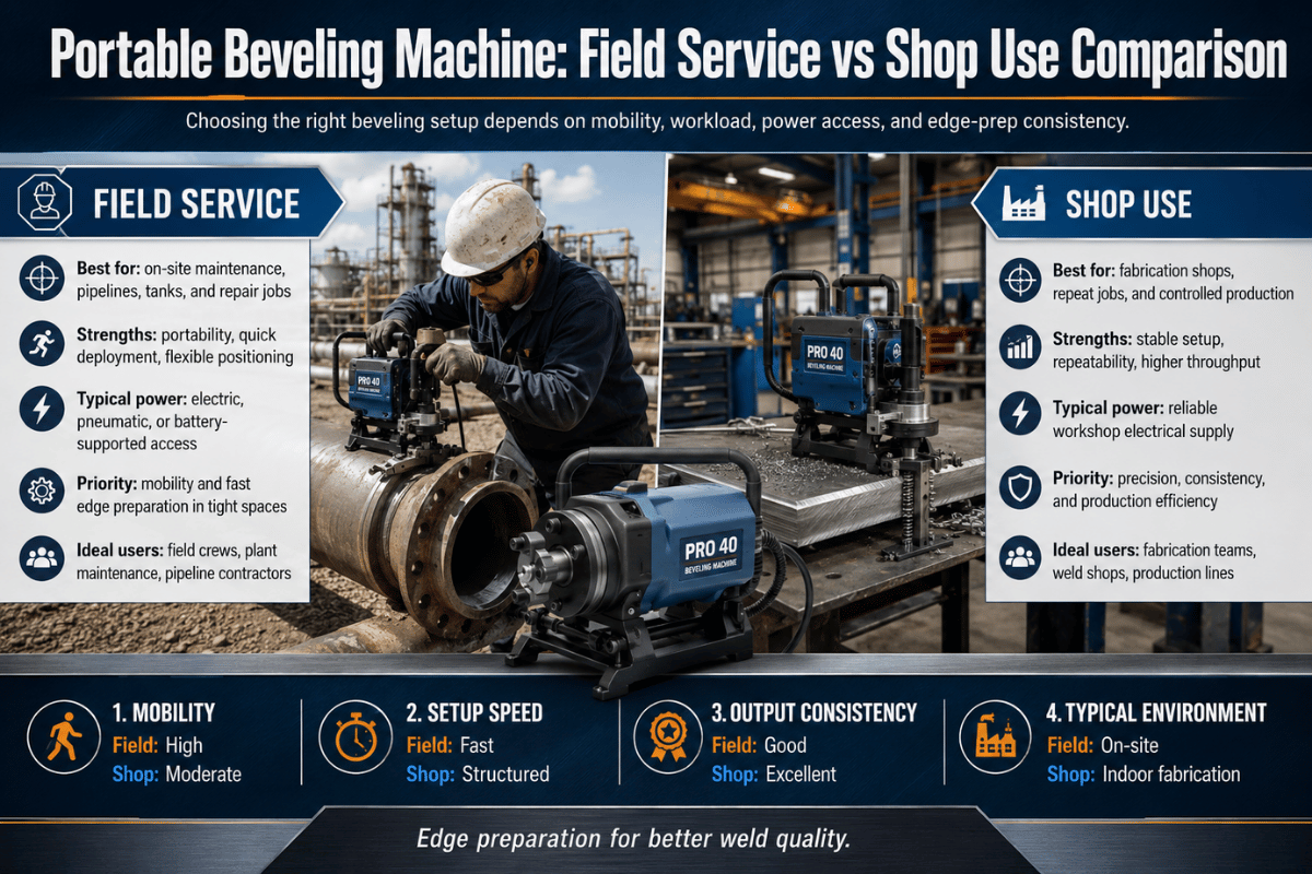
How to Choose a Plate Beveler: Decision Framework
Choosing a plate beveling machine involves mapping four variables — material, thickness, throughput, and portability — to a machine category. For portable beveling (field or jobsite use), portability and guide system type dominate the decision. This specification grid applies to most structural, shipbuilding, and process industry fabrication.
- If material is stainless steel, Duplex, Inconel, or high-strength (S690 / AR plate) AND quality-critical application
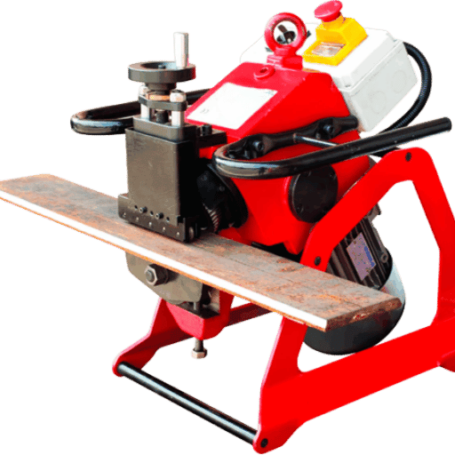
→ Cold milling beveler with carbide inserts. No HAZ, no oxide, weld-ready immediately. - If plate thickness 6–40 mm + high production volume + straight edges only
→ Auto-feed milling plate beveler (stationary or self-propelled) for throughput and geometrical consistency. - If high volume + thin-to-medium plate (6–38 mm) + long straight runs
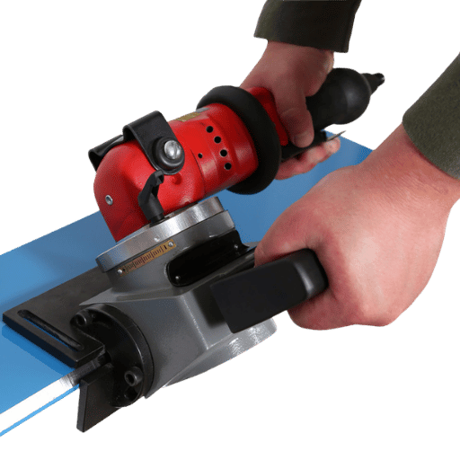
→ Roller shear / peel beveler for maximum speed (up to 10 FPM) and lowest cost per linear meter. - If field work + irregular or curved plate edges + moderate thickness (<40 mm)
→ Portable milling beveler (rotary type preferred over nibbler for ergonomics and straight-edge consistency). - If nuclear, O&G, or aerospace application + J-bevel or complex groove geometry required
→ Multifunction CNC milling beveler (0°–90° angle range, J-bevel, facing, cladding prep capability). - If occasional use + volume <50 LM/week + budget-constrained
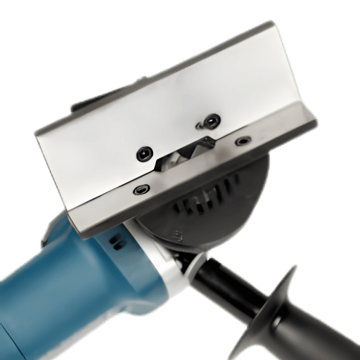
→ Handheld plate beveler (milling type handles up to ~40 mm at standard angles with indexable carbide inserts).
5 Key Specification Questions Before Buying
- Power (kW or HP): match your most demanding material/plate thickness for one pass beveling. AR and stainless steels need more power for consistent insert engagement without chatter. Typical portable hand-held: 1-2.2 kW; auto-feed production: 2-5+ kW.
- Maximum bevel depth or diagonal: Entry level portable milling bevelers suit ≤15-16 mm/30° bevel depth. Auto-feed production machines: typically 40-80 mm diagonal. Heavy multifunction: 80-120 mm. Match the deepest plate needed.
- Range of angle and method of adjustment: Range 15-60 covers most structural weld prep. 0-90 possible for facing and J-bevel. Confirm tool-free operation of angle switches/repeatability – digital readout preferred for production work.
- Type of carbide insert and any supply issues in your region: Side- or face-mount indexable (edge-changing) inserts rather than solid carbides allow more economy with lower cost per insert and multiple suppliers for spare tooling in most regions. Confirm this before source selection.
- Weight of beveler and method of guide: For portable bevelers, machine weight commonly an ergonomic constraint. The guide system: fence or wheel bearing. Both provide consistent bevel image; generally the fence gives higher angular accuracy on a long edge; bearings are effective on irregular contours.
For detailed product specifications, see the RESIZE milling and beveling machine lineup, or review our broader beveling machine guide.
Beveler requirements for a regulated project?
The RESIZE project engineering team has in-depth experience in specification to production stage needs and broad material types, plate thickness range, and weld code requirements for structural steel fabricators, shipyards, and pressure vessel fabricators.
Plate Beveling Trends 2025–2026
Growing volumes of steel fabrication projects and rising global plate demand support this trend. According to market estimates of global market revenue for industrial and building projects respectively, the edge preparation machine market is estimated at around $400 million in 2026 and forecast to nearly $575 million in 2035 at a CAGR of around 4.2% – spurred on by infrastructure spending in Asia-Pacific and more demanding weld edge specs in regulated sectors. [Market estimates based on industry reports, not independently verified data.]
Industry surveys indicate that by 2025, most fabrication shops will have either replaced or be in the process of updating their edge preparation practices to Automated Beveling. Three technical plate beveler procurement drivers are evolving plate beveler design trends:
- CNC automation and robotic integration. In 2025, peer-reviewed research validated in the field displays robotic plasma and automated mechanical beveling systems with ultrasonic adaptive measurement, culminating in the automatic compensation for plate thickness tolerance and the reduction of operator-input dimensional error. For structural steel applications, parallel technology operating advances in chip-removal cold milling, servo fed automated system.
- Cold cutting preference — reinforced by code. AWS D1.1:2025 adds new CVN toughness testing provisions, an updated Annex S covering additional base materials, and Load/Resistance Factor Design clauses. These changes strengthen the regulatory case for cold mechanical beveling in seismic, offshore, and nuclear applications — sectors where HAZ hardening above 350 HV is a disqualifying defect in governing WPS documents.
- Zero-fume compliance pressure. Occupational health regulations in the EU, UK, and major Asia-Pacific markets are tightening permissible exposure limits for metal fume. Cold mechanical beveling generates no fumes — only recoverable metal chips. Another structural driver emerges for switching from plasma and oxy-fuel edge preparation to milling-based beveling: regulatory adherence across enclosed fabrication facilities regardless of pure productivity arguments.
Frequently Asked Questions
What is the difference between a bevel and a chamfer?
View Answer
What bevel angle is required for structural steel welding?
View Answer
Can I use an angle grinder instead of a plate beveler?
View Answer
How does plate thickness affect which beveling method to choose?
View Answer
Plate thickness is the chief machine factor. Thin-to-medium (6-38 mm) plate can be processed by practical and economical roller shear or handheld milling machines. Medium (6-80 mm) plate is best by an auto feed milling beveler for maximum throughput and edge quality.
Heavy (60-120 mm+) plate’s needs can only be met by high amperage or multi-function milling systems. Thick plate can be plasma bevelled, but slow feed speed at high angles means at best a 400A system takes 50 mm thick plate through 45 bevels at 9–10 IPM which for production applications would be several times slower than mechanical in throughput terms. On high strength thick plate plasma also produces HAZ’s and complicates weld pre-qualification.
See what beveling machines are used for across different plate thickness ranges.
What is a HAZ and why does it matter for weld quality?
View Answer
Heat-affected zone (HAZ). The zone of parent metal adjacent to a thermally cut or welded edge that has undergone changes in microstructure and/mechanical properties due to heat with no melting of material – is known as the HAZ. During thermal plate beveling (plasma, oxy-fuel) a HAZ of 1-3 mm is formed around the cut edge, even before the parent material has been welded.
Peer-reviewed published data on the oxy-fuel beveling (2025) hardening a S355J2N structural steel HAZ is reported as 250-450 HV1 when compared with the parent parent steel at around 170-190 HV. This pre-existing hardened zone is known to reduce the fatigue strength,provide preferential zones of cold cracking in high strength steel grades, and create wear issues on any carbide tooling used subsequently to working on the same edge. Cold mechanical beveling creates no HAZ, and leaves the parent steel’s mechanical properties unchanged.
References & Sources
- Kawiak M., Sajek A. – ‘Evaluation of quality and effectiveness of edge preparation for S355J2N steel sheet in the application of welding’ – Advances in Materials Science 25(2):17-35, June 2025. West Pomeranian University of Technology in Szczecin. DOI: 10.2478/adms-2025-0007.
- Plowe R. (Koike Aronson Inc.) – “Plasma beveling: What is achievable with modern equipment?” – The Fabricator, June 2011.
- Kelechava B. – “AWS D1.1:2025 – Structural Welding Code, Steel” – ANSI Blog, May 2025. Brief about of AWS D1.1/D1.1M:2025, 23rd edition.
- Sheridan G. (TRUMPF) – ‘Three optional techniques for beveling’ – The Fabricator, 2004.
- GBC Spa — “How to Choose a Plate Beveling Machine: Complete Buying Guide” – GBC Industrial Tools, December 2025
About This Analysis
RESIZE develops and produces intelligent cold milling and beveling systems for structural steel manufacturing, shipbuilding, and pressure vessel manufacturing. This brochure is based on peer-reviewed metallurgical research, published welding code references, and technical trade press reports to present an objective comparison of various beveling techniques including data that sometimes does not prove a mechanical method’s case, such as plasma’s speed benefit in thin plate at low volume. The HAZ Hidden Cost Framework is derived from our engineering group’s report on total-cost edge prep, in several fabrication fields and material groups.
RESIZE develops cold milling and beveling machines for weld preparation in structural fabrication and regulated industries. Technical content is reviewed for accuracy against current welding codes and production engineering practice before publication.

