
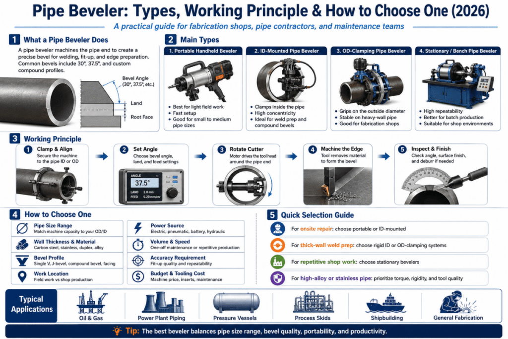
A pipe beveler is the piece of equipment that determines whether your weld gets approved or returns for rework. Selecting the wrong kind—whether that means different type, or choosing the right type at the wrong specifications—is the most common, avoidable expense in pipe fabrication. This article reviews every kind of pipe beveler, the cutting principle they operate, and a 7-step method you can use for your next purchase, with bevel angles mapped to AWS D1.1, ASME B31.3, and API 1104.
Quick Specs
| Working Range | 0.5″–24″ (≈12–610 mm) typical; up to 40″ with extension kits |
| Bevel Angles | 0°–60° adjustable (37.5° most common single-V; 30° pipeline; 45° structural) |
| Power Options | Pneumatic, Electric (corded/brushless/battery), Hydraulic |
| Wall Thickness | ≤38 mm portable; >40 mm typically requires bench/CNC compound bevel |
| Tool Slots | 1–3 (facing, counterboring, beveling — multi-slot enables single-pass prep) |
| Angle Accuracy | CNC stationary ±0.5° / Electric portable ±1° / Pneumatic ±1–2° |
| Standards | AWS D1.1 · ASME B31.3 · ASME B16.25 · API 1104 · ISO 9692 |
What Is a Pipe Beveler? (And Why Edge Prep Decides Weld Quality)
A pipe beveler is a powered tool that prepares the end of a pipe to be joined by cutting the end at an angle. The beveled edge gives the welder a starting point for delivering a full penetration weld. The created groove contains the filler metal, manages the heat input, and provides penetration for the root pass between the two pipe ends.
Any welder can produce poor fusion or lack of penetration without the proper prepared geometry.
The three other applications the machine differs from a saw, a grinder and a chamfering tool. A saw is not capable of making the cut at an angle other than 90 as it cuts perpendicular to pipe axis. An angle grinder removes material but is impractical to keep the same angle over whole circumference of pipe.
A chamfering tool adds a small decorative or deburring edge (less than 30), not the full depth weld groove of beveler. The pipe beveler holds consistent degrees (30, 37.5, 45) over the full end of pipe repeatably weld joint after weld joint, user.
Why this is important: AWS D1.1 Structural Welding Code – Steel and ASME B31.3 Process Piping both specify the edge preparation is to be in accordance with a qualified Welding Procedure Specification (WPS). A WPS is a document where the geometry you have tried to emulate is written down. Since weld procedures are tested by geometry, a deviation in bevel shape is good enough cause for Non-Conformance —even if the finished weld looks perfect.
For a more thorough explication of the larger category, see our description of what is a beveling machine and the purpose of beveling in fabrication.
How a Pipe Beveler Works: The Cutting Principle in 60 Seconds
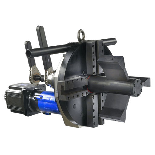
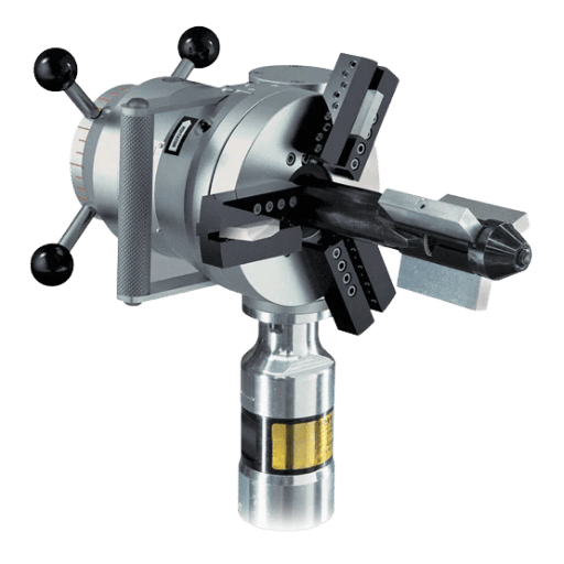
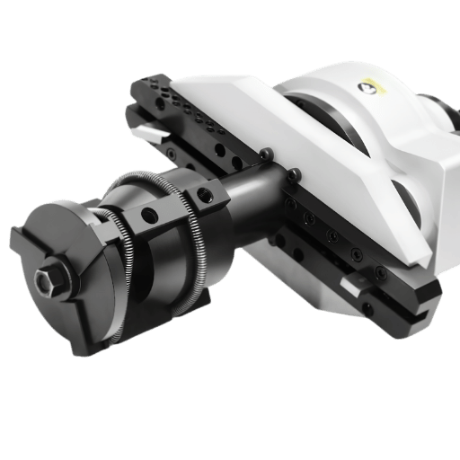
The pipe beveler clamp on to the pipe, then rotates the tool head to the end of the pipe while removing material with carbide inserts at a preset angle. It can be separated into four main components: a clamping system, a drive, a rotating tool head and the cutting inserts.
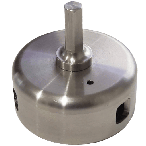
The clamping system is the feature that distinguishes a professional beveler from a hobby tool. There are two types of universal clamp systems. The first clamps from within by expanding an internal mandrel inside the pipe tube.
This type of clamp is very accurate, fast and is the most common type if the pipe ID can be accessed. The second type bores external clamping jaws onto the outside of the pipe tube. This is the only choice of clamp for heat exchanger tube sheets and any other applications where you cannot get to the inside of the pipe tube.
Data from GBC industrial machines can give a guide where mandrel clamping systems can be used. Their data shows clamps that will do from 10 mm ID at the small end up to 1,016 mm (40″) at the large end, depending on class of machine.
Once the pipe is made up in the machine, the tool head will rotate around the pipe axis and cut the bevel in one revolution. The classes are defined by the range of revolutions per minute (rpm): a portable bevelers range from 5-120 rpm with huge torque (for thick wall steel ) while a stationary and CNC bench machine can range from 2000-6000 rpm on the cutter head with quite smaller diameter inserts. The drive can be pneumatic (preferred for ATEX or the inherent hazardous areas), electric (the main new purchase) or hydraulic.
Carbide is the cut. The specific insert has a set geometry – flat, radius, or J-profile. The same operator can go from a V-bevel to a J-bevel without changing the machine by swapping inserts.
A typical suggested chip load formula used on industrial CNC’s and posted on many practitioner sites is chip load = cutter diameter/200. Tool life for carbide is given in linear ft of cut, not hours of run time. One insert can prep 50-300 ft of MS (mid-wall) carbon steel before edge failure, depending on the material and coolant.
Cold mechanical beveling maintains the pipe at ambient temperature during the cut. Zero heat-affected zone (HAZ); no oxide scale; no microstructural change at the edge. This has been affirmed in GBC’s cold-beveling technical guide, Fractory’s heat-affected-zone analysis, and The Fabricator’s heat-affected-zone reference.
The steels it works best on are stainless, duplex, and nickel-based alloys: thermal cuts on these materials induce a depleted chromium band or modify the austenite-ferrite ratio and thus reduce corrosion resistance during operation.
5 Types of Pipe Bevelers: Portable, Bench-Top, CNC, Cold-Cut, and ID/OD-Mounted
One way to categorize the market is at five functional levels, separated by the location of the work, the method used by the machine to grip and support the pipe, and its level of automation. The 5-type taxonomy has replaced the marketing buckets (“light-duty,” “industrial,” “heavy-duty”) with procurement-relevant specifications as follows:
| Type | Pipe Size | Wall Thickness | Where It Works | Typical Industries | Price Band |
|---|---|---|---|---|---|
| Portable ID-mounted | 0.5″–12″ | ≤25 mm | Field, on-site, in-place | Pipeline, oil & gas, plant maintenance | $1,500–$8,000 |
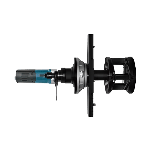
| Portable OD-mounted | 2″–24″ | ≤30 mm | Heat exchangers, blocked-ID work | Power generation, petrochemical | $3,500–$15,000 |
| Bench / Stationary | 1″–24″ | ≤40 mm | Shop, fixed station | Fabrication shops, prefab spool yards | $8,000–$25,000 |
| CNC Automated | 2″–40″ | Up to 120 mm with compound bevel | High-volume production lines | Pressure vessel, shipbuilding, nuclear | $25,000–$80,000+ |
| Plastic / PVC dedicated | 2″–24″ | SDR-rated plastic walls | Field or shop | Drainage, water service, HDPE fusion | $200–$2,500 |
Two distinctions are worth pointing out. First, the cold-cut versus hot-cut division cuts through these types-though most contemporary pipe bevelers are mechanically (cold-cut)- flame and plasma cutting are still employed for initial-stage rough prep using mechanically finishing. Second, ID-mounted versus OD-mounted is a clamping choice-not a product distinction-in the same chassis a single brand usually has both clamping systems.
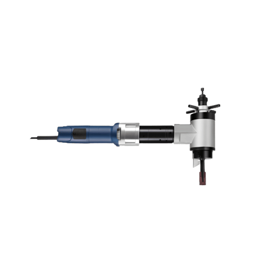
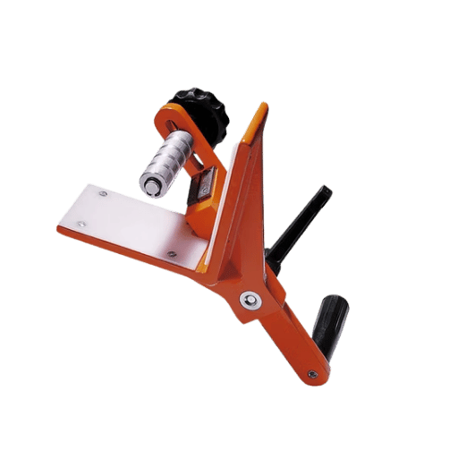
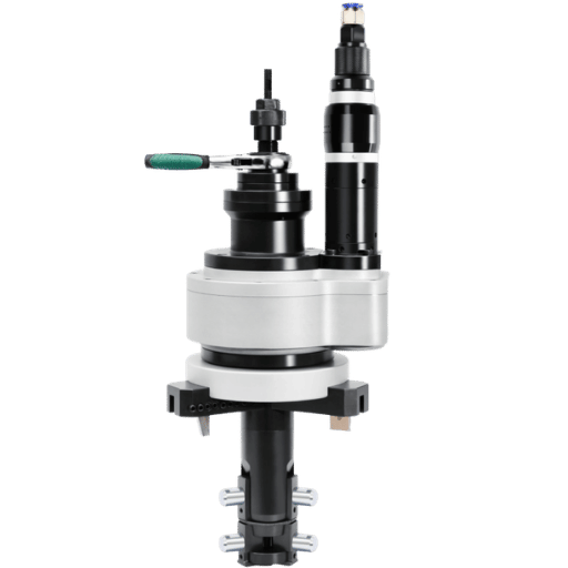
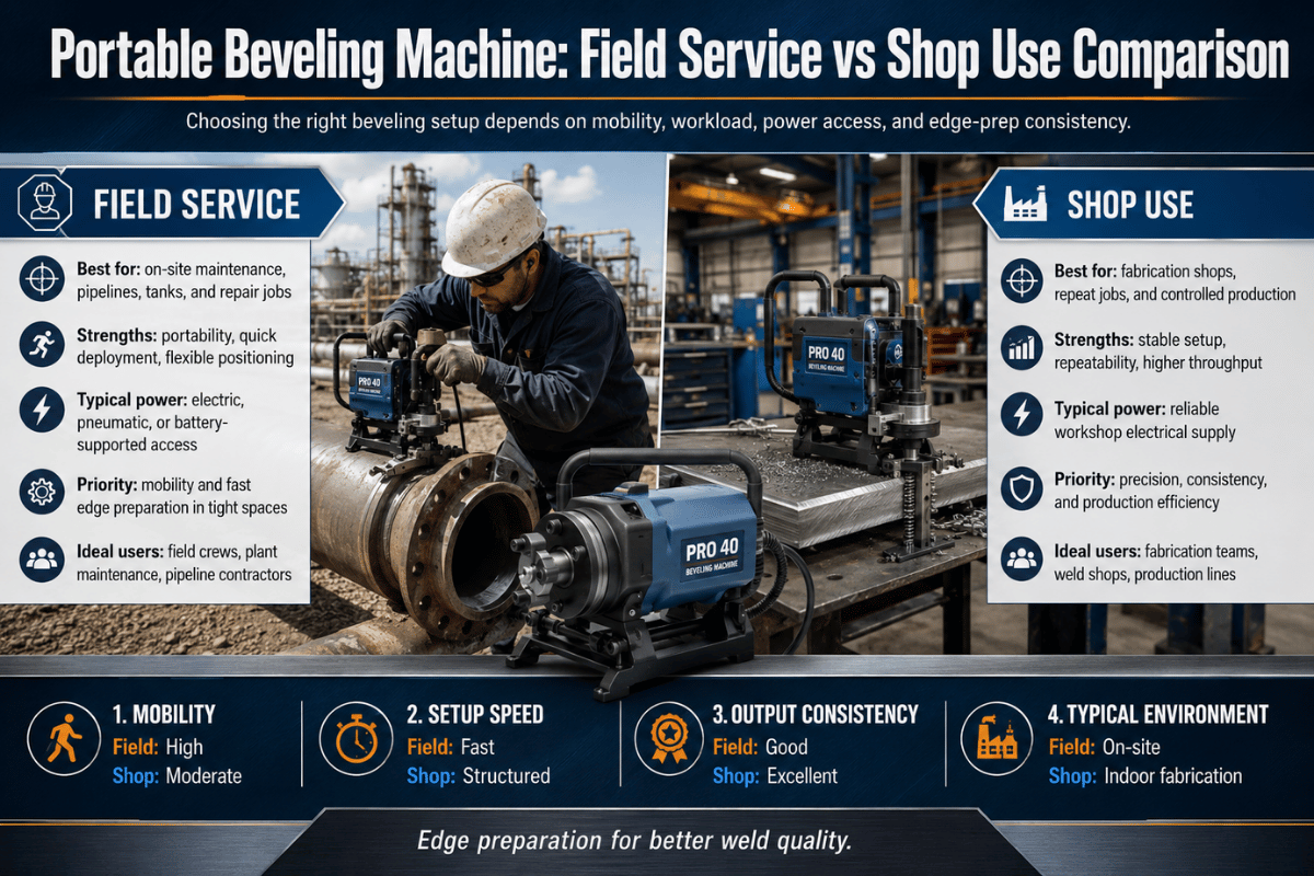
What is a portable pipe beveler?
A portable pipe beveller is a modular machine, typically 18-60 lbs (8-27 kg.) which is portable by a craftsman to the pipe being beveled, rather than vice-versa. The machine is clamped on the pipe using an internal mandrel or external jaws, then the head rotates around the pipe end beveling it in a single pass. Searches for “portable pipe beveller” increased some ten times in 2025 (DataForSEO Google Ads data: 30 monthly searches in May 2025, to 320 by September 2025), indicating that we are seeing clearer movement toward existing-on-sitenew pipe prep for construction projects and pipeline tie-in points. Portable bevelers typically are adjustable for any pipe diameter in the .5-24 range, and handle up to about 30mm of wall thickness before the user needs to step up into a bench or CNC class. The tradeoff: precision angle control of a CNC machine, holding 0.5. Where precise angle determines weld integrity, compared to typical 1.0 sub-1.0 weld prep on many critical-service welds though: OSWPS calls for 2.5 tolerance.
Material-Specific Bevelers: Steel, Stainless, PVC, and HDPE Plastic
The same bezel cannot be applied to every material with the same insert. Superficially similar at the cutting edge, steels and PVCs differ greatly at the tool, feedrate, and cooling strategy parameters. Combine the wrong tool with the wrong parameters, and you get ridging on plastics or quick wear on stainless.
| Material | Recommended Tool | Cooling | Watch-Out |
|---|---|---|---|
| Carbon steel (A53, A106) | Carbide insert, V or J profile | Air or light cutting oil | Burr formation on thin wall — finish with a deburring pass |
| Stainless steel (304, 316) | Coated carbide (TiAlN), reduced feed | Synthetic coolant required | Work-hardening — avoid dwell, keep feed continuous |
| Duplex / super-duplex | Premium coated carbide, slower RPM | High-volume coolant flood | Phase ratio sensitive to local heat — cold mech only |
| Inconel / nickel alloys | Ceramic or premium carbide | Coolant flood | Tool wear cost dominates — quote inserts separately |
| PVC / CPVC | Router bit or HSS cutter | Air only — no liquid coolant | Heat = melt-back; reduce feed at deeper cuts |
| HDPE (butt-fusion prep) | Planar facer, not insert-style | Air only | Surface flatness more critical than angle |
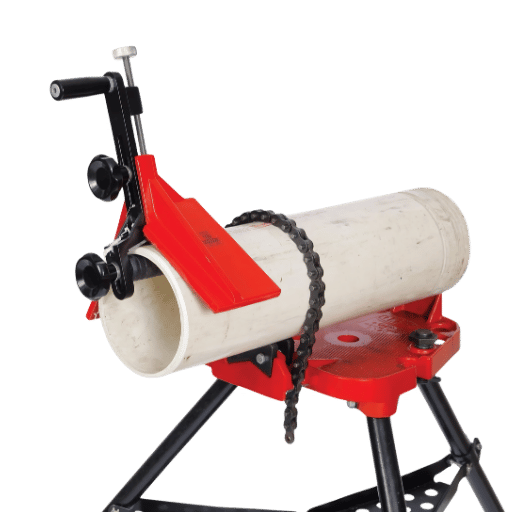
Can a beveling tool be used on PVC pipe?
Yes, but not with the same insert used on steel. PVC bevellers use a router bit or high-speed steel cutting tool which shears the plastic without generating enough heat to melt the edges. Most plastic-bevelling tools operate without coolant, with air providing sufficient heat removal, and run at significantly higher RPMs and lower feeds than steel bevelling. Used on residential drain and irrigation pipe, the Bevel Pro tool—which is a flush- or high-low-handled mechanism—produces a 15° bevel on C-35 or SDR 26 pipe end in roughly ten seconds per pipe end. Used on HDPE butt-fusion prep, the tool body switches to a planar facer with a perpendicular face to produce a flat, not beveled, surface for the bond. Use a steel insert on PVC and you’ll end up with a glazed, melted ridge into which your Solvent Cement can entrap; use a PVC router bit on Schedule 40 steel and you’ll break or dull the bit in minutes.
Bevel Geometry and Standards: V, J, U, and K Grooves Explained
Geometry is where most quality problems and most rework begin. The bevel angle is one variable; the land (or root face), root opening, and grove type all are equally critical and equally code-dependent. The four geometries most likely to be encountered in process and structural piping are V, J, U, and K—none of which are joined without the right wall thickness and process welding specifications to go along with it.
| Groove | Wall Range | Typical Angle | When to Use | Filler Volume |
|---|---|---|---|---|
| Single-V | 5–20 mm | 37.5° bevel (75° included) | One-side access, GTAW or GMAW | Baseline (1×) |
| Double-V (X-bevel) | 15–40 mm | 37.5° each side | Two-side access, reduces filler | ~50% of single-V |
| J-prep | 15–40 mm | 10°–20° with rounded radius | Heavy wall, one-side access | ~40% of single-V |
| U or K-groove | >40 mm | 10°–15° with deep radius | Nuclear, high-pressure thick wall | ~30% of single-V |
The values above are derived from the joint geometries detailed in ISO 9692-1 Welding and allied processes — Recommendations for joint preparation, and cross-checked against AWS D1.1 prequalified joint details. The single-V at 37.5° per side (75° included) is the default for operational used in ASME B16.25 standard weld end geometry on 22 mm wall pipe that feeds into ASME B31.3 process piping.
Code requirements vary. This is where shops bleed profits. Kedes Machine’s industry cheat sheet documents a fabrication shop losing a $200,000 contract by cutting 37.5° bevels on a pipeline job that called for 30 °, per API 1104-the bevels were present but did not match the qualified WPS, thus each joint had to be reworked. Takeaway is operational: there is no “one-angle-fits-all.”
“There is no standard angle. Cutting a 37.5° bevel because that’s what everybody does is why you have to rework joints or fail inspections. There is only one right angle-it’s the one in your qualified WPS.”
— Dongmei Guo, Founder, Kedes Machine (15+ years pipe-beveling manufacturing)
| Code | Bevel Angle | Tolerance | Root Face |
|---|---|---|---|
| ASME B16.25 (referenced by B31.3) | 37.5° (≤22 mm wall) | ±2.5° | 1.5 mm ±0.5 mm |
| AWS D1.1 (CJP prequalified) | 45° single bevel | ±5° | 0–3 mm typical |
| AWS D1.1 (PJP) | 30° minimum | ±5° | Per joint detail |
| API 1104 (mainline pipeline) | 30° | ±5° | 1.6 mm ±0.8 mm |
| API 1104 (facility) | 37.5° | ±2.5° | 1.6 mm ±0.8 mm |
For complete code references and understanding the difference between bevel angle and included angle, see our companion guides to beveling standards, groove weld symbols, and edge weld quality and inspection.
Above 15 mm wall, changing from a single-V to a J-prep will typically cut filler-metal volume and welder arc time by 60% or more. The cost is having a radius-profile insert (more costly, wears slower, slower cutter feed rate) and tools that will maintain the radius shape without error – which seems impossible, according to ISO 9692. For most thick-wall structural & pressure vessels, J-prep machining costs justify the tooling spend after rough-beveling just 200 joints.
Critical Specs to Compare: OD/ID Range, RPM, Tool Slots, Wall Thickness
When quotes for similarly specified pipe bevelers come in drastically different, the data sheet reveals the “what makes it capable?” list of five: working range, wall-thick rating, tool slots, rpm/ feed, re-clamp accuracy.
- Working range (OD or ID)-Locate rated min/max plus dead band, where the mandrel cannot engage (most gearboxes have a 0.5″-1.0″ dead band between mandrel size).
- Wall thickness rating-Listed maximum assumes single-V cut. Derate by 0.30 for J-prep or compound bevels. “40 mm wall” typically translates to 28 mm J-prep.
- Tool slots-One slot for just bevels, two for facing, three for counterboring. Multi-slot prep machines deliver the full join geometry in one setup, eliminating re-clamp fit-up errors.
- RPM & feed control-Options between coarse or smooth RPM control (electronic or pneumatic regulator) are more benefit than v-max RPM. Do you want stainless and steel to feed differently, or force to be a compromise (fixed RPM speeds)?
- Clamping repeatability-Ask for mandrel “concentricity TIR” (total indicator runout) after re-clamp. Anything above 0.25 mm shows up as inconsistent circumferential bevel flatness.
Industry published equipment accuracy data, though not from common neutral test std, can be give an idea of practical working:
Due to API 1104 max tolerance of 5 vs. 2.5 for ASME B16.25, a handheld electric beveler at1,would only have 2.01 to 4.95 taking the tight angle into account-roughly half the tolerance budget back to the operator.
How to Choose a Pipe Beveler: 7-Step Selection Framework
The framework below runs through seven decisions in order. Each one eliminates candidate machines further, so by number seven you normally have one or two matches that are the best value. This framework has been assembled from public welding code requirements as well as field practice in structural, process and pipeline work – it is not “one machine brand’s advice.”
- Material first. Steel, stainless, plastic and exotic alloys all need different insert and feed strategies. If you generate two materials, you should have two insert sets; not necessarily two machines – just make sure the chassis is rated for both.
- Determine the pipe OD with the 90% rule. Select the machine whose mandrel diameter exceeds 90% of the diameters you expect to cut this year, not the largest you have ever seen. Edge-case maximum large pipe will most likely be sent out for shop or subcontract work.
- Determine the wall-thickness ceiling. Build in a derate (25%) for the J-prep. Today, if you are cutting a 30 mm wall, you will need a 40 mm rated machine if you might J-prep tomorrow.
- Make a decision about site or shop. Field operations > 24″ pipe = portable. Production runs of identical joints = bench or CNC. Combination environment = portable with stationary backup is more economical than dedicated CNC.
- Match bevel shape to program. Single-V tooling will serve 80-90% of ASME B31.3 applications. If you will require API 1104 mainline (30 degrees) and B31.3 (37.5 degrees), you will need an adjustable angle machine rather than fixed-angle units.
- Choose drive based on environment. Pneumatics for ATEX/Explosive atmosphere. Electric (corded or battery) for general construction. Hydraulic for mainline or offshore pipeline. Electric is now the most popular choice for new machinery, barring ATEX.
- Factor in volume and duty cycle. Less than 50 joints/week = portable. 50-500 = bench mounted. Over 500 joints/week = CNC usually amortizes within 18 months, based on standard North American labor rates.
Material OD 90% Wall 1.25 Site vs Shop Geometry Procedure Drive Environment Volume Duty Cycle. Run the seven decisions in order; when the first single result occurs, there is your machine category. If two categories of machine survive each of the seven decisions, the less expensive is the winner.
A contrarian note from a Practical Machinist forum thread: for a single small-diameter pipe bevel, an experienced fitter wielding a15″ double-cut bastard file can probably beat any portable beveler in finishing the joint before that portable unit is unboxed and clamped. Tacking together the purchase of a machine for one yearly weld makes no real sense; above framework assumes long-term volume.
For an eye-opening look at how the machinery functions, see our pillar on professional milling and beveling machines, which lists working ranges and price bands by configuration.
Pricing and ROI: What $1,500 vs $30,000 Actually Buys You
The 20 difference between the least and most expensive pipe bevelers illustrates the capability cliffs that are purchased: clamp accuracy, pipe size range, automated vs. manual. Below are the 2025-early 2026 public price bands for new equipment from the dominant SERP results -Steelmax, Tri Tool, Reed, Mathey Dearman and Amazon platform listings -and RESIZE’s own portable and bench ranges. Prices below are for reference only, they are a frequent snapshot and do not necessarily reflect current market pricing. For a quote on recent prices, please contact us directly.
| Price Band | What You Get | Capability Cliff |
|---|---|---|
| $200–$2,500 | PVC / plastic dedicated tools, manual hand bevelers, basic ID-mounted carbon-steel portable | Wall under 12 mm, single material, no facing/counterboring |
| $2,500–$8,000 | Pneumatic or electric portable, mandrel kits 2″–12″, single-V cuts | Wall under 25 mm, 1–2 material types, single tool slot |
| $8,000–$15,000 | Heavy-duty portable, multi-slot tooling (face/bevel/counterbore), wider OD/ID range | Wall up to 30 mm, J-prep capable, electric variable-speed drive |
| $15,000–$31,000 | Bench / stationary, bench with auto-feed, larger OD up to 24″ | Wall up to 40 mm, repeatable production, CNC entry-level |
| $31,000+ | Full CNC, automated feed, large diameter (24″+) and compound bevels | High-volume production, ±0.5° accuracy, integrated PLC |
A simple ROI calculation: (manual prep time savings per joint) (loaded labor rate) (joints/year) (machine cost)=Year 1 payback if positive. A portable beveler that saves 8 mins. per joint at a $75/hr. loaded rate, applied to 1,200 joints/year, offers about $12,000 of of saved labor- payback a $5,000-$8,000 portable in just under year. Economics turn against the machine below about 200 joints per year unless quality rework cost can be considered and capital cost amortized separately.
Common Mistakes and On-Site Best Practices
The mistakes that drive rework on a beveling job are documented across welding industry references, and they are remarkably consistent. Miller Electric’s nine common pipe-welding issues and Kedes Machine’s WPS-compliance case studies converge on the same five preventable errors.
- Cutting avoid checking the WPS bevels. The most costly mistake on-site. The bevel that” looks right” is the one that was qualified for your weld procedure. Always check qualification before first cut.
- Reading bevel angle as included angle. A drawing stating “75° groove” can be taken to mean 37.5° per side (correct) or 75° per side (incorrect – a 150° included angle; wrong). Confirm with owner before machining.
- Incorrect root face thickness. Too thick, over 3mm, causes lack of penetration; too thin, under 1mm, leads to burn-through. The 1.5-1.6mm 0.5-0.8mm range in ASME B16.25 and API 1104 is a deliberate compromise.
- Applying a stick-welding joint prep to TIG. These two processes have very different joint design strategies; day to day, sticking causes lack of fusion. When welding dirty orifice components, Stick welding can operate with a 1/8″ gap and a 3/32″ knife-edgeland;tig and RMD wire processes need a 1/8″-5/32″ gap and a 3/32″ knife-edgeland. Treating all three the same produces root lack of fusion.
- Missing the flat-grind after plasma or oxy-filing pipe prepping. These two processes leave a layer of oxides around the cut edge that produce porosity, inclusions, or lack of fusion. Use of cold-beveler with abrasive wheel grind cuts avoid this and are one of the strongest practical reasons to specify or use them, especially on critical-service pipe.
Industry participants report a sixth problem that log-ins not address on inspection sheets: equipment improvisation. Hacks shown to work for non-critical service and small runs, including the ubiquitous Ridgid 300 pipe threader with grinder, show up regularly on discussions ontheor keogs. The folk position on this use “it works for non-critical, small, one-shot jobs; it does not work for code work.”
A field example to illustrate the cost: a fabrication shop in the southeastern USA cut 37.5° bevels for a 20-mile pipeline tie-in project specified per API 1104 (30° required). No problem with the angle, but it was outside the qualified WPS. All 480 joints had to be ground, re-prepped, and re-welded. Labor alone, at $85/hr loaded with two crews, exceeded $200,000. Correct machine, ok bevel;, just failed to read project spec before setting angle.
To see a parallel field example with a more favorable cost of raw material, see our companion guides on pipe weld fit-up and beveling vs chamfering.
Industry Outlook: Electric Drives, Smart Bevelers, and AI-Adaptive Cutting
Three curves are shifting pipeline unit costs through 2027 and well beyond, and each has data current enough to influence a purchase made today.
Electric versus air. Reports and Data values the electric pipe-beveler market at USD 0.45 billion in 2024, projected to reach USD 0.85 billion by 2034. A LinkedIn industry trend forecast out 2025 values the segment CAGR at 5.6% from 2026, faster than the overall beveling machine market: 4.16%. Top drivers are improved battery technology aboard a brushless motor that can run a full-shift, and the removal of compressors on most construction sites (Business Research Insights, $0.4 billion in 2026, climbing to $0.57 billion in 2035).
Smart adaptive cutting. Pemamek’s 2026 welding-automation outlook emphasizes AI-adaptive welding and digital twins, while the same engineering is directed toward the bevel: in cut angle and feed sensors that adjust parameters on-the-fly, compensating for pipe ovality or wall thickness variation. This was first demonstrated by suppliers in 2024; it is now hitting production CNC bevelers starting in 2025-2026.
Code convergence to cold cuts. ISO 9692 already demands that Jbevels and U-bevels on pipe too thick for thermal cutting meet tolerances too tight for welding. EN 1090 and ISO 3834 build on this for CE-marked construction, demanding that welds or piping component fit / finish have the same precision. In practice, if your shop is doing structural / CE-marked, nuclear, or pressure vessel pipe, you will be moving toward a colder, mechanical automated beveler before too long – not the opposite.
Planning capital spend for 2026? Then a practical consideration is establishing an electric drive preference over pneumatic, investing in multi-slot capacity for J-tapers, and allocating budget for an replacements for-carbide insert kits EOM at a rate of one per 12-18 months depending on the work rate. The machine commissioned now will still be in service to cut 2031, the inserts will not.
Frequently Asked Questions
Q: What is the difference between beveling and chamfering?
View Answer
Q: What angle should I bevel a pipe for welding?
View Answer
Q: Can a portable pipe beveler handle schedule 80 stainless steel?
View Answer
Q: How long does a carbide insert last on a pipe beveler?
View Answer
Q: Do I need a different machine for PVC versus steel pipe?
View Answer
Q: What is the cheapest reliable pipe beveler for a small shop?
View Answer
Need a pipe beveler matched to your pipe size and wall thickness?
RESIZE offers portable, bench, and CNC-ready pipe beveling and milling machines that cover pipe OD from 0.5″ to 24″ and wall thicknesses of 40 mm. Technical data sheets, capabilites, and configurations are available on this product page.
About This Guide
This guide to pipe bevelers uses AWS D1.1, ASME B31.3, B16.25, API 1104, and ISO 9692 code citations, compared against technical guides and practitioner forum discussions from 2024-2026. The 7-step selection methodology was derived from public codes and real-field examples – not a specific brand. Validated by RESIZE’s engineers based upon bevel functionality, materials, and equipment specifications.
References & Sources
- AWS D1.1 / D1.1M:2020 Structural Welding Code — Steel — American Welding Society
- ASME B31.3 Process Piping Guide – Los Alamos National Laboratory Engineering Standards
- ISO 9692-1 Welding and allied processes — Recommendations for joint preparation — International Organization for Standardization
- Pipe Welding Techniques to Avoid 9 Common Issues – Miller Electric
- Cold beveling for pipes and plates: a complete guide — GBC Industrial Tools
- Heat Affected Zone — Causes, Effects, and Reduction — Fractory
- All you need to know about the heat-affected zone — The Fabricator
- Pipe Bevel Angles by Code: ASME, AWS & API Cheat Sheet — Kedes Machine
- Electric Pipe Beveling Machines Market – Forecasts and Trends – Reports and Data
- Trends shaping welding automation in 2026 — Pemamek
Related Articles
- What is a beveling machine — definitions and core categories
- Beveling standards: AWS, ASME, API, and ISO 9692 explained
- Pipe weld fit-up — root face, root opening, and tolerance
- Groove weld symbols and how to read welding drawings
- Beveling vs chamfering — operations, tools, and standards
- The ultimate guide to pipe welding positioners


